Slate raven User manual

Slate Control User Manual
This guide contains information on the expanded functions of the SLATE CONTROL,
diagrams of connections and basic functions, and some example setups.

Overview
The Slate Control includes several expanded features, some of which are hiding in plain sight
and some of which are actually hidden. They are described in detail in this document, as
well as basic functionality.
Table of Contents:
★Overview
★Tools
★Control Head Function Diagram
★Rack Unit Connections
★Control Room Panel Expanded Features
★VU Meter DB9 “VU AUX”
★Remote Talkback DB9 “TB AUX”
★Solo System
★Auto Talkback System
★Reverse Talkback System
★Mute Cue when Talkback is active
★Pin Configurations, DB25
★Pin configurations continued, DB9
Tools
★Most of the SLATE CONTROL features require no extra tools, however it is handy to have the
following:
○Multimeter
○#2 Phillips driver
○Tone Generator
○Tweaker (Small, non-magnetic flat blade screwdriver used for aligning electronics)
○Analyzer (A Minilyzer from NTI is great
○Multifunction Generator (A Minirator from NTI is great)
Slate Control Expanded Functions Page 1
SLATE CONTROL FUNCTIONS
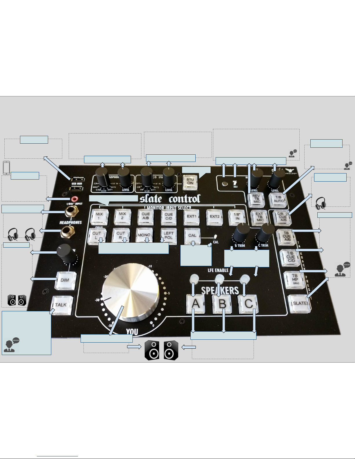
CONTROL HEAD FUNCTIONS WITH EXAMPLE SETUP
TALKBACK
Press this to talk!
Assignments are handled in
the TALKBACK PRESET area.
Momentary switch, use TB
FOOTSWITCH or TB AUX for
latching.
DIM
Scalable
CONTROL ROOM
DIM. Lowers the
Control Room
volume by the
level set on the
knob. Still
functional in CAL
mode. Switched
on automatically
when TALKBACK
is engaged.
LOCAL HEADPHONES
Source and level selected
in the HEADPHONE AREA.
Third output on the rear
of the control head.
⅛” INPUT
TRS input sized for phones,
players, laptops, etc. Level is
bumped from -10 to +4.
Selectable for the CR, LOCAL
HEADPHONES and CUE C/D.
CONTROL ROOM VOLUME
Relay switched
in 1db increments
SPEAKER SELECTION
Selects which speaker pairs (A, B or C) is
sent the CONTROL ROOM source.
Controlled by CONTROL ROOM
VOLUME. LFE ENABLE per speaker pair.
B & C SPEAKER Trims
Allows tweaking of
B & C speaker pair volumes
relative to the A speaker level.
TALKBACK PRESET
This is where you
decide WHO you
are talking to
when you press
TALK. CUE A/B,
CUE C/D, LOCAL
HEADPHONES,
and SLATE (Mix
outputs) are
INDEPENDANTLY
selectable.
CAL MODE
Disables CONTROL
ROOM VOLUME.
Control Room level is
set at CAL trimpot
CR 2 CUE A/B
At CUE A/B output,
replaces CUE A/B signal
with the selected
CONTROL ROOM SOURCE.
TB AUTO
Latches TALKBACK in the
ON position, unless signal
is presented at AUTO TB
Inputs on EXT INPUT DB25
USB HUB
High current USB hub. Powered even
when not connected to a computer.
USB connection on Control Head rear.
EXPANDED CONTROL ROOM FUNCTIONS
See manual for detailed descriptions
Internal Talkback mic with preamp adjustment,
external talkback mic selector, master talkback
level, REVERSE TALKBACK enable and level.
REVERSE TALKBACK injects the REV TB MIC into
the CONTROL ROOM whenever TALKBACK is
enabled.
TALKBACK CONTROL & SOURCE
Selects the source for the LOCAL HEADPHONES
and sets the level. Global for all three LOCAL
HEADPHONE outputs. Selections are CR, MIX 2,
CUE A/B, CUE C/D, EXT1, EXT2 OR ⅛”.
LOCAL HEADPHONE control
Selects the source for the CUE C/D and SLS
(Studio Loudspeakers) outputs and sets the
level. Global for all CUE C/D and SLS
outputs. Selections are OFF, CR, LOCAL
HEADPHONES, CUE C/D, EXT1, EXT2 OR ⅛”.
CUE C/D control
ENABLES SLS OUTPUT
CONTROL ROOM SOURCE SELECTIONS

DB9
TALKBACK AUX
XLR-F
EXTERNAL & REVERSE
TALKBACK INPUT
DB25
MAIN INPUTS
DB25
EXTERNAL INPUTS
XLR-M
LFE OUTPUT
Connects to
CONTROL HEAD
DB9
VU AUX
DB25
SPEAKER OUTPUTS
DB25
CUE OUTPUTS
These four stereo inputs come directly
from your DAW and are labeled
MIX 1, MIX 2, CUE A/B & CUE C/D.
Use this input if you wish to
use an external talkback mic
instead of the built-in mic on
the control head. Phantom
power is not provided.
This input
provides for
REVERSE
TALKBACK as
described in the
user manual.
Phantom power
is not provided.
Inputs for two external stereo sources, plus
inputs to the SOLO system & the AUTO
TALKBACK system.
LFE (subwoofer)
output, with LPF &
crossover point, phase
and level. Selectable
per speaker pair on the
CONTROL HEAD.
DB50 Cable connection to the CONTROL HEAD.
Bi-directional control voltage, ⅛” and local
headphone signals travel over this cable.
Ships with a 25’
cable, 50’ cable
is available.
This DB9 provides thorough access to the
Talkback system, for various
customizations to the user’s system. Use
this to create a remote producer talkback
station, for instance. Pinouts are described
in the user manual.
Pre-fader Control Room output for
connecting to external VU meters.
Voltage and Solo System Logic are
available here as well. Pinouts are
described in the user manual.
This DB25 connects the SLATE CONTROL to
your speakers. Carries the selected source to
speaker pairs A B & C, and the SLS source to
the SLS (Studio Loudspeaker) outputs.
Switched at the CONTROL HEAD.
Line level, TRS mirror of the local headphone feed to the
CONTROL HEAD. Same source and level control as the
CONTROL HEAD’s headphones. Connect to an external
headphone amp or other line-level input. Carries talkback
when TB to HP is selected.
This DB25 carries the MIX and CUE
outputs for connecting to an external
cue system, external headphone amps,
mixdown decks, or other line-level
inputs determined by the user.
MIX 1 output
always carries
the MIX 1 input
and carries
talkback when
TB TO SLATE is
selected. Line
Level.
MIX 2 output
always carries
the MIX 2 input
and carries
talkback when TB
TO SLATE is
selected. Line
Level.
CUE A/B output always
carries the CUE A/B input,
except when “CR to CUE
A/B” is selected. It then
carries the CR Source. CUE
A/B Carries talkback when
TB to CUE A/B is selected.
Line Level.
The CUE C/D output is selectable on the
CONTROL HEAD from the following
sources: Control Room (CR), Local
Headphones (HP), CUE C/D input, External
1, External 2, ⅛” input, Off. Level is also
controlled on the CONTROL HEAD. Carries
talkback when TB to CUE C/D is selected.
Line Level.
MIX 1 MIX 2 CUE A/B CUE C/D
¼” TRS
LOCAL HEADPHONE
LINE OUT
EXTERNAL HEADPHONE AMP EXTERNAL HEADPHONE AMP
EXTERNAL HEADPHONE AMP
DAW RETURN, MIX DECK,
HEADPHONE AMP, ETC.
DAW RETURN, MIX DECK,
HEADPHONE AMP, ETC.
SLATE CONTROL CONNECTIONS
STEREO MONITOR CARD WITH EXAMPLE SETUP
TALKBACK FOOTSWITCH
DB25 PINOUT printed
right on the chassis

Control Room Panel Expanded Features
★Cut Left
○Cuts (as in disables, mutes, turns off, etc.) the LEFT speaker output, with no change to the
input signal. Engaging this during normal, stereo monitoring will result in hearing the
RIGHT channel of the selected input source coming out of the RIGHT speaker only. During
MONO monitoring, results in hearing the MONO SUM of the selected input source in the
RIGHT speaker only.
★Cut Right
○Cuts (as in disables, mutes, turns off, etc.) the RIGHT speaker output, with no change to the
input signal. Engaging this during normal, stereo monitoring will result in hearing the LEFT
channel of the selected input source coming out of the LEFT speaker only. During MONO
monitoring, results in hearing the MONO SUM of the selected input source in the LEFT
speaker only.
★Mono
○Sums the selected input source to MONO in the CONTROL ROOM ONLY. Handy for judging
stereo image, phase correlation, and general awesomeness of your mix among other things.
As described above, sums BEFORE the speaker cuts to allow true MONO mixing on ONE
SPEAKER.
★Left Pol
○Flips the polarity (phase) of the LEFT CHANNEL of the selected input source. Handy for
checking phase coherence of a mix, stereo width, etc. When combined with MONO will play
only the difference (side) information from a stereo signal summed to the center channel.
★CAL Mode
○Disables the CONTROL ROOM VOLUME and replaces it with the CAL pot, accessible with a
tweaker on the front panel. Use this to pre-set a reference level, either with a sound level
meter or by feel, to ensure exacting level reproduction. Very useful when mixing for film &
television. CAL mode is still affected by the DIM control.
VU AUX DB9
★This DB9 deals largely with the VU meter outputs, which are provided as a courtesy for those who
wish to purchase or build a glowing set of wonderful VU meters.
○Two pins on the VU AUX DB9 carry signals to drive a pair of VU meters. They are derived
from the selected CONTROL ROOM SOURCE and are PRE FADER. Pin 4 carries the left signal
and pin 9 carries the right.
○Ground is available on pins 1 and 5.
○+15 volts is available on pin 2, - 15 volts on pin 6.
○+12 volts for meter lamps is available on pin 3.
○This DB9 contains the switching logic for the SOLO SYSTEM, described below. Connect pin 8
to pin 7 to engage the SOLO SYSTEM.
○Pin configuration:
1. Ground
2. +15 volts
3. +12 Volts
4. VU Left
5. Ground
6. -15 volts
7. Solo Logic -
8. Solo Logic +
9. VU Right
Slate Control Expanded Functions Page 2

TB AUX DB9
★This DB9 is packed full of things to make a remote talkback station for the producer. Use them in this
way or split them up as you see fit. Here is what you’ll need to know:
○You can add another EXTERNAL TALKBACK MIC on this connector. It is parallel with the
EXTERNAL TALKBACK XLRF on the rear of the card, so use caution if connecting both at the
same time. Phantom power is NOT provided. Pin 2 is Mic -, Pin 6 is Mic +, Pin 7 is Mic
Ground.
○The TALKBACK preamp signal is available on pin 8, in case you would like to send it to the
front desk, another studio, an underground AM radio station, or any such place that suits
you.
○TALKBACK and DIM are switchable on this connector. Pin 4 is TALKBACK logic, pin 3 is DIM
logic. Connect either to the ground on pin 9 to remotely switch their function.
○+5 volts is available on pin 5 for LED indicators, or other functions as needed.
○Pin Configuration:
1. Ground
2. Mic -
3. Dim Logic
4. Talkback Logic
5. +5 Volts
6. Mic +
7. Mic Ground
8. Talkback Preamp Output
9. Logic Ground
Solo System
★The SLATE CONTROL is designed to function not only as a stand-alone monitor controller, but also as
the center-section of a modular console. To that end, it has been fitted with a SOLO SYSTEM that may
be incorporated into said modular console, used in conjunction with your DAW, or used in any
number of creative ways.
○On the EXT INPUT DB25, cable pairs 5 & 6 input to the SOLO SYSTEM. When using the logic
circuit described above on the VU AUX DB9, engaging the SOLO SYSTEM will replace the
CONTROL ROOM SOURCE with the SOLO SYSTEM INPUT. When the SOLO SYSTEM is active,
the MIX 1 lamp will turn purple if MIX 1 is selected, red if any other source is selected.
Auto-Talkback System
★The SLATE CONTROL is equipped with an AUTO TALKBACK system. When T/B AUTO is selected on
the control head panel, Talkback will latch on until signal is presented to the AUTO T/B INPUT on
cable pairs 7 and/or 8 of the EXT INPUT DB25. Suggested uses:
○Mult the MIX 1 signal or your DAW’s main mix out to the input. When playback stops,
talkback will open up. If using this method, an open mic going through the MIX 1 or your
DAW main mix outputs may result in closing the talkback momentarily. This may actually
be desirable when working with a singer or band, but if it is not an alternative method is
listed below.
○Print a tone to a pair of tracks in your DAW (or a single track) and send this output
exclusively to the AUTO T/B Input. When playback is active, Talkback will drop out. When
playback is stopped, Talkback will engage and stay latched REGARDLESS of any throughput
on MIX 1 or any other input.
Slate Control Expanded Functions Page 3

Reverse Talkback System
★It is often desirable to inject a signal into the CONTROL ROOM
when TALKBACK has been activated.
For instance, let’s say you have a band out in the live room. The drummer is surrounded by drum
mics, so you may be able to hear them speak through them, but the bass player may be nowhere
near an open mic. In a situation such as this, one would simply put a microphone out in the live
room, connect it to the REV T/B MIC INPUT, engage REV T/B on the CONTROL HEAD, and voila! Using
the REV T/B level control, you can inject the microphone you placed in the live room into the
CONTROL ROOM whenever TALKBACK is engaged. No more giving up a channel of D/A and
muting/unmuting the signal inside your DAW. True large-format console functionality at your
fingertips!
Mute Cue when Talkback is active
★There is an internal option on a small jumper to mute the CUE OUTPUTS whenever TALKBACK is
engaged. Use this option if you wish to fully interrupt the signal going out CUE A/B and CUE C/D
when talkback is engaged. The jumper is located on the main STEREO MONITOR card.
Example Patchbay Layouts
★These two layouts represent how a simple studio using only one 96-point TT patchbay can take
advantage on the full power of the SLATE CONTROL!
★Many other choices are, of course, equally valid. These are simply options to get you thinking...
Slate Control Expanded Functions Page 4

DAW OUTPUT 5-8
MULT
XBOX TV
EXT 1 EXT 2 SOLO AUTO T/B
SLATE CONTROL EXT INPUTS
HEADPHONE MIX SYSTEM 1-8
MIX 1 MIX 2 CUE A/B CUE C/D
SLATE CONTROL CUE OUTPUTS
DAW OUTPUT 1-8
MIX 1 MIX 2 CUE A/B CUE C/D
SLATE CONTROL MAIN INPUTS
MIC PREAMP OUT 1-8
MIC PANEL OUT 1-8
DAW INPUT 1-8MIC PREAMP INPUT 1-8
MIC PREAMP OUTPUT 1-16
DAW INPUT 1-16
DAW OUTPUT 1-8
MIX 1 MIX 2 CUE A/B CUE C/D
SLATE CONTROL MAIN INPUTS
MIX 1 MIX 2 CUE A/B CUE C/D
SLATE CONTROL CUE OUTPUTS
DIGITAL
MIX
DECK
ANALOG
MIX
DECK
HP AMP
BAND
HP AMP
SINGER
DIGITAL
MIX
DECK
ANALOG
MIX
DECK
EXT 1 EXT 2 SOLO AUTO T/B
SLATE CONTROL EXT INPUTS
DAW OUTPUT 9-16
REAMP
SYSTEM
BUS
COMP
BUS
EQ
OUTBOARD GEAR

Pin Configurations
There are four DB25s on the main card. These are the cable pair designations based on the standard pinout.
1. Main Inputs
1.1. Mix 1 Left
1.2. Mix 1 Right
1.3. Mix 2 Left
1.4. Mix 2 Right
1.5. Cue A
1.6. Cue B
1.7. Cue C
1.8. Cue D
2. Cue Outputs
2.1. Mix 1 Left
2.2. Mix 1 Right
2.3. Mix 2 Left
2.4. Mix 2 Right
2.5. Cue A
2.6. Cue B
2.7. Cue C
2.8. Cue D
3. Speaker Outputs
3.1. Speaker A Left
3.2. Speaker A Right
3.3. Speaker B Left
3.4. Speaker B Right
3.5. Speaker C Left
3.6. Speaker C Right
3.7. SLS Left
3.8. SLS Right
4. Aux I/O
4.1. External 1 Left
4.2. External 1 Right
4.3. External 2 Left
4.4. External 2 Right
4.5. Solo System In L
4.6. Solo System In R
4.7. Auto Talkback Signal 1
4.8. Auto Talkback Signal 2
Slate Control Expanded Functions Page 5

Pin Configurations Continued
There are two DB9s. These are the pin numbers in a standard DB9.
1. T/B Aux
1.1. Gnd
1.2. External TB Mic -
1.3. Dim Logic
1.4. Talkback Logic
1.5. +5v
1.6. External TB Mic +
1.7. External TB Mic Gnd
1.8. Talkback Preamp Out
1.9. Logic Ground
2. VU Aux
2.1. Ground
2.2. +15v
2.3. +12v
2.4. Left VU Driver
2.5. Ground
2.6. -15v
2.7. Solo Logic Ground
2.8. Solo Logic
2.9. Right VU Driver
Slate Control Expanded Functions Page 6
!
!
!"#$%&'%()#&$%*+,-"-./&
&(0123435678&79&*78974:65;&<(7*=&
In#accordance#to:#ISO/IEC#17050-1#EN#17050-1#
!
EMC$Directive!2014/30/EC!-!FCC$PART!15!SUBPART!B!SECTION!15.107!&!15.109!
Low$Voltage$Directive:!2014/35/EU!-$RoHS!2011/65/EU-!
REACH$Regulation!EC!1907/2006!–!WEEE$2012/19/EC!
$
!"#$%&'%()#&$%*+,-"-./>&!50?08&!2350@&
8331#Lookout#Mountain##
#
Los#Angeles,#CA#90046#
#
323-656-2050#
#
#
#
A47BC15&!D01696135678E@&
Trade#Name:#Slate#Media#Technology#
#Model:#Raven#MTX#mk2;#Slate#Control#
Description:#46”#Touch#Display#Panel;#Monitor#Controller#
#
F0&G040H;&B012340&C8B04&7C4&E720&40ED78E6H6265;&5G35&5G0&D47BC15&G04068&6B0856960BI&57&JG61G&5G6E&
B0123435678& 402350EI& 6E& 68& 178974:65;& J65G& 5G0& essential$ requirements$ 38B& other$ relevant$
requirements$79& 5G0&%C47D038& A34263:085I& %C47D038& *7C8162I& 38B& :005E& 322& 40KC640:085E& 79& 5G0&
*383B638& )85049040810L*3CE68M& %KC6D:085& N0MC235678EO& <Cet$ appareil$ numérique$ de$ la$ classe$ B$
respecte$toutes$lecs$exigences$du$ Règlement$sur$le$ matérial$brouilleur$du$ Canada=,&%'*&(640156?0&
PQRS>TQ>%*I& U**& A345& RV& ECHD345& 0W& E015678& RVORQX& Y& RVORQZ&"[(& PQRS>TV>%\I& N7+!&
PQRR>]V>%\I&N%#*+&N0MC235678&%*&RZQX>PQQ]I&F%%%&PQRP>RZ>%*O$$G0&D47BC15&6E&17:D26385&J65G&
5G0&97227J68M&E538B34BE&38B>74&75G04&874:356?0$B71C:085E@&
&
Radiated!Emissions!/Immunity:!
EN$55032$(2012)$+C1;$Class$B,$EN$6100-3-2$(2014),$EN$61000-3-3$(2013)$
#
#
Safety:!
#
#
#
#
Environmental:#
%,&]RQQLSLT&<PQQ]=^#R^#PI&%,&]RQQLSLP&<RZZV=^#R^#PI&%,&]RQQLSL]&<PQQX=&
%,&]RQQLSLV&<PQQ]=I&%,&]RQQLSLRR&<PQQS=&
%,&]QQ]V@&PQQP&#R&<PQQ]=&^#P&<PQRQ=&^#RP&<PQRR=&^#*&<PQQX=&
)%*&]Q]V&<0BOX=I&)%*&]QQ]V&<0BOX=I&)%*&]QQ]V&Z0BOX=I&3:P&
\"&]QQ]V&%B65678&X&_&N0?6E678&(350&PQRT>QX>PS&
*!#&*PPOP&,-&]QQ]VLQT&<6812O&3:08B:085E&RYP=&
%,&VQV`R@&PQRP&
&
!CDD20:08534;&)8974:35678@&
#
!
Notified#Body#Involved:#
!NB0976,!CKC!Certification!Services,!LLC!Report!No.:!98060-5,6!
Technical#File#Creation#by:#
Intertek!as!per!IEC62321!and!in!compliance!with!EN50581!
&
!
$G0&C8B04E6M80B&B012340E&78&H0G329&79&5G0&:38C9315C404&5G0&0KC6D:085&83:0B&3H7?0&G3E&H008&B0E6M80B&57&17:D2;&
J65G&5G0&4020?385&E015678E&79&5G0&3H7?0&409040810B&ED01696135678@&
&
&
&
&
&
Signature!of!Authorized!Person!
Place!and!Date!of!Issue!(of!this!DoC)!
!
Erika!Earl!
!
Director!of!Hardware!Engineering!
Written!Name!
Title!
#
Table of contents
Other Slate Recording Equipment manuals


