CHD Elektroservis VS-MIDI 8-434 User manual
VS
VSVS
VS-
--
-MIDI
MIDIMIDI
MIDI
MIDI Interface for
MIDI Interface forMIDI Interface for
MIDI Interface for
Vermona Synthesizer
Vermona SynthesizerVermona Synthesizer
Vermona Synthesizer
Model 8
Model 8Model 8
Model 8-
--
-434
434434
434
Version 2.0
Version 2.0Version 2.0
Version 2.0
Installation Manual
Installation ManualInstallation Manual
Installation Manual
© 2022 CHD Elektroservis
© 2022 CHD Elektroservis© 2022 CHD Elektroservis
© 2022 CHD Elektroservis
www.chd
www.chdwww.chd
www.chd-
--
-el.cz
el.czel.cz
el.cz

Vermona Synthesizer MIDI Interface
Vermona Synthesizer MIDI InterfaceVermona Synthesizer MIDI Interface
Vermona Synthesizer MIDI Interface
VS
VS VS
VS-
--
-MIDI
MIDIMIDI
MIDI Installation
Installation Installation
Installation Manual
Manual Manual
Manual
8
88
8-
--
-434 /
434 /434 /
434 / v. 2.00
v. 2.00 v. 2.00
v. 2.00
Copyright © 2022 CHD Elektroservis. All rights reserved.
No part of this publication may be reproduced in any form without the written permission of CHD Elektroservis.
2
2
2
2
Contents
ContentsContents
Contents
Page
PagePage
Page
1
11
1 INTRODUCTION
INTRODUCTIONINTRODUCTION
INTRODUCTION ................................
................................................................
................................................................
................................................................
................................................................
................................................................
.....................................................
..........................................
..................... 3
33
3
1.1 MIDI INTERFACE KIT PARTS .......................................................................................................................3
1.2 GENERAL INFORMATION...........................................................................................................................3
1.3 INTERFACE CONNECTION..........................................................................................................................4
2
22
2 INSTALLATION PROCEDURE
INSTALLATION PROCEDUREINSTALLATION PROCEDURE
INSTALLATION PROCEDURE................................
................................................................
................................................................
................................................................
................................................................
................................................................
......................................
............
...... 5
55
5
2.1 THE INSTRUMENT DISASSEMBLY...............................................................................................................5
2.2 MIDI DIN SOCKETS INSTALLATION.............................................................................................................5
2.2.1 HOLES FOR MIDI SOCKETS DRILLING.........................................................................................................5
2.2.2 MIDI SOCKETS MOUNTING........................................................................................................................6
2.3 INSTALLATION OF BUNCHED CABLES WITH 5-PIN CONNECTOR AND LED ................................................7
2.3.1 CONNECTION TO POWER SUPPLY BOARD.................................................................................................8
2.3.2 LED INDICATOR REPLACEMENT.................................................................................................................8
2.4 INSTALLATION OF BUNCHED CABLES WITH 7-PIN CONNECTOR ...............................................................9
2.5 INTERFACE BOARD INSTALLATION ..........................................................................................................12
2.5.1 INTERFACE BOARD PLACEMENT..............................................................................................................12
2.5.2 CONNECTION OF CABLES.........................................................................................................................13
2.5.3 SELECTION OF THE INSTRUMENT VERSION.............................................................................................14
2.6 INSTRUMENT RE-ASSEMBLY....................................................................................................................15
3
33
3 INSTALLATION TIPS
INSTALLATION TIPSINSTALLATION TIPS
INSTALLATION TIPS................................
................................................................
................................................................
................................................................
................................................................
................................................................
................................................
................................
................16
1616
16
3.1 MIDI INPUT AND OUTPUT ....................................................................................................................... 16
Vermona Synthesizer MIDI Interface
Vermona Synthesizer MIDI InterfaceVermona Synthesizer MIDI Interface
Vermona Synthesizer MIDI Interface
VS
VS VS
VS-
--
-MIDI
MIDIMIDI
MIDI Installation
Installation Installation
Installation Manual
Manual Manual
Manual
8
88
8-
--
-434 /
434 /434 /
434 / v. 2.00
v. 2.00 v. 2.00
v. 2.00
Copyright © 2022 CHD Elektroservis. All rights reserved.
No part of this publication may be reproduced in any form without the written permission of CHD Elektroservis.
3
3
3
3
1
11
1
INTRODUCTION
INTRODUCTIONINTRODUCTION
INTRODUCTION
1.1
1.11.1
1.1
MIDI INTERFACE KIT PARTS
MIDI INTERFACE KIT PARTSMIDI INTERFACE KIT PARTS
MIDI INTERFACE KIT PARTS
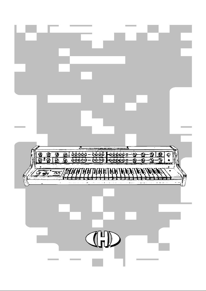
Fig. 1.1.1
Fig. 1.1.1 Fig. 1.1.1
Fig. 1.1.1 -
--
- Parts of VS
Parts of VS Parts of VS
Parts of VS-
--
-MIDI interface kit
MIDI interface kitMIDI interface kit
MIDI interface kit
The MIDI interface kit contents all
necessary parts for installation incl. all
support and coupling elements. The
delivery also includes both installation
and operation manuals in printed
form. Please check if the delivery is
complete before the installation (see
fig. 1.1.1):
1. MIDI Interface board
2. Bunched cables with 7-pin
connector
3. Bunched cables with 5-pin
connector and LED
4. 2x DIN-5 socket with cable
5. Coupling elements (screws, tooth-
lock washers, nuts and insulation
tube)
6. Owner’s and Installation manuals
in printed form
1.2
1.21.2
1.2
GENERAL INFORMAT
GENERAL INFORMATGENERAL INFORMAT
GENERAL INFORMATION
IONION
ION
Mounting the interface in the Vermona
Synthesizer is very easy. If you follow
the instructions from this manual, there should be no major problems during the installation. The interface
installation procedure is thoroughly described in the following chapters. Please follow these instructions
accurately to avoid any damage of the instrument.
Attention! Disconnect the instrument form the mains prior to the installation. There is a risk of the
Attention! Disconnect the instrument form the mains prior to the installation. There is a risk of the Attention! Disconnect the instrument form the mains prior to the installation. There is a risk of the
Attention! Disconnect the instrument form the mains prior to the installation. There is a risk of the
electric shock!
electric shock!electric shock!
electric shock!
Attention! Observe precautions for handlin
Attention! Observe precautions for handlinAttention! Observe precautions for handlin
Attention! Observe precautions for handling electrostatic discharge sensitive devices!
g electrostatic discharge sensitive devices!g electrostatic discharge sensitive devices!
g electrostatic discharge sensitive devices!
The producer is not responsible for any eventual mechanical or electrical damage of the instrument
The producer is not responsible for any eventual mechanical or electrical damage of the instrument The producer is not responsible for any eventual mechanical or electrical damage of the instrument
The producer is not responsible for any eventual mechanical or electrical damage of the instrument
caused by the infringement of the described installation procedure or by careless manipulation during
caused by the infringement of the described installation procedure or by careless manipulation during caused by the infringement of the described installation procedure or by careless manipulation during
caused by the infringement of the described installation procedure or by careless manipulation during
the inst
the instthe inst
the installation of the MIDI interface!
allation of the MIDI interface!allation of the MIDI interface!
allation of the MIDI interface!
It is recommended to calibrate the instrument accordingly to the instructions in service manual of the
It is recommended to calibrate the instrument accordingly to the instructions in service manual of the It is recommended to calibrate the instrument accordingly to the instructions in service manual of the
It is recommended to calibrate the instrument accordingly to the instructions in service manual of the
instrument prior the interface installation. This ensures trouble
instrument prior the interface installation. This ensures troubleinstrument prior the interface installation. This ensures trouble
instrument prior the interface installation. This ensures trouble-
--
-free operation of the interface.
free operation of the interface.free operation of the interface.
free operation of the interface.
The cover of the instrument will not be markedly damaged during the installation. The physical appearance of
the vintage instrument remains nearly the same as before the installation. If necessary, the interface can be
simply removed and the instrument restored back to original appearance.
All original circuits of the Vermona Synthesizer remain without any modification. The instrument can be used
the same way as before the retrofitting.

Vermona Synthesizer MIDI Interface
Vermona Synthesizer MIDI InterfaceVermona Synthesizer MIDI Interface
Vermona Synthesizer MIDI Interface
VS
VS VS
VS-
--
-MIDI
MIDIMIDI
MIDI Installation
Installation Installation
Installation Manual
Manual Manual
Manual
8
88
8-
--
-434 /
434 /434 /
434 / v. 2.00
v. 2.00 v. 2.00
v. 2.00
Copyright © 2022 CHD Elektroservis. All rights reserved.
No part of this publication may be reproduced in any form without the written permission of CHD Elektroservis.
4
44
4
1.3
1.31.3
1.3
INTERFACE CONNECTION
INTERFACE CONNECTIONINTERFACE CONNECTION
INTERFACE CONNECTION
The interface is connected to the VCO, EG, VCF, VCA and power supply boards of the instrument. The following
diagrams (figs. 1.3.1, 1.3.2) explain the electrical connection of the interface in the instrument.
Fig. 1.3.1
Fig. 1.3.1 Fig. 1.3.1
Fig. 1.3.1 –
––
– Connection to the instrument
Connection to the instrument Connection to the instrument
Connection to the instrument
Fig. 1.3.2
Fig. 1.3.2 Fig. 1.3.2
Fig. 1.3.2 –
––
– Block diagram of the interface function
Block diagram of the interface function Block diagram of the interface function
Block diagram of the interface function
Vermona Synthesizer MIDI Interface
Vermona Synthesizer MIDI InterfaceVermona Synthesizer MIDI Interface
Vermona Synthesizer MIDI Interface
VS
VS VS
VS-
--
-MIDI
MIDIMIDI
MIDI Installation
Installation Installation
Installation Manual
Manual Manual
Manual
8
88
8-
--
-434 /
434 /434 /
434 / v. 2.00
v. 2.00 v. 2.00
v. 2.00
Copyright © 2022 CHD Elektroservis. All rights reserved.
No part of this publication may be reproduced in any form without the written permission of CHD Elektroservis.
5
5
5
5
2
22
2
INSTALL
INSTALLINSTALL
INSTALLATION PROCEDURE
ATION PROCEDUREATION PROCEDURE
ATION PROCEDURE
2.1
2.12.1
2.1
THE INSTRUMENT DISASSEMBLY
THE INSTRUMENT DISASSEMBLYTHE INSTRUMENT DISASSEMBLY
THE INSTRUMENT DISASSEMBLY
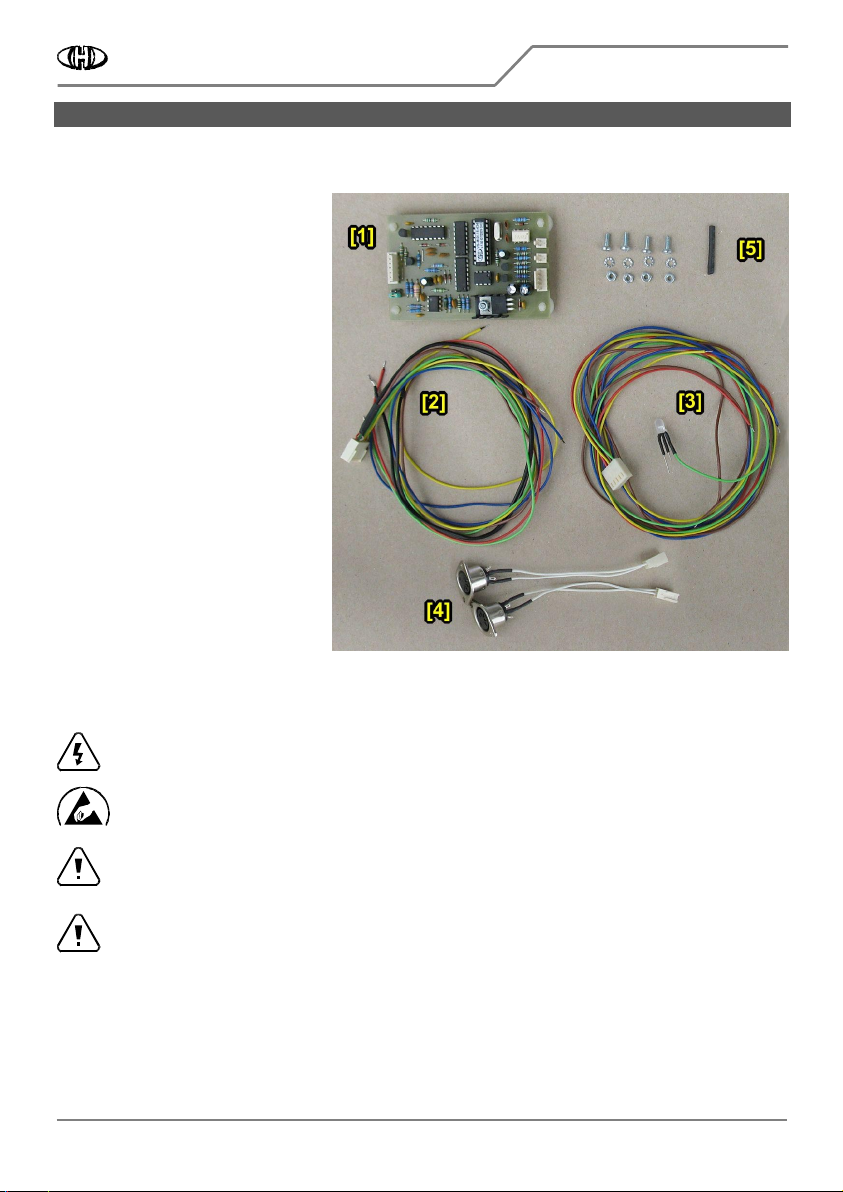
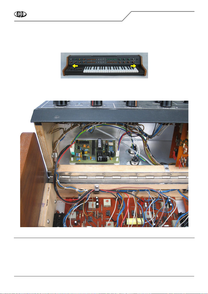
a) Unscrew the two screws on the top cover of the instrument (fig. 2.1.1). Keep the screws and washers. They
will be used again after the MIDI kit installation is finished.
Fig. 2.1.1
Fig. 2.1.1Fig. 2.1.1
Fig. 2.1.1
Fig. 2.1.2
Fig. 2.1.2Fig. 2.1.2
Fig. 2.1.2
b) Carefully lift up the instrument’s top cover and turn it back (fig. 2.1.2). All instrument’s parts and boards
needed for the interface installation are now accessible (fig. 2.1.3).
Fig. 2.1.3
Fig. 2.1.3Fig. 2.1.3
Fig. 2.1.3
VCO VCA POWER
SUPPLY
SWITCH
+ LED
VCF
EG
INTERFACE
2.2
2.22.2
2.2
MIDI DIN SOCKETS INSTALLATION
MIDI DIN SOCKETS INSTALLATIONMIDI DIN SOCKETS INSTALLATION
MIDI DIN SOCKETS INSTALLATION
The interface has both MIDI input and output. However, only MIDI input is necessary for basic operation of the
interface (i.e controlling the instrument by MIDI commands). The MIDI THRU/OUT output socket need not to be
installed (see chapter 3.1) if you don’t require transfer of MIDI data to another MIDI devices (THRU function) or
reverse communication of the interface with MIDI host system (OUT function). Nevertheless, having both MIDI
input and output is more convenient for an easy integration in a more advanced MIDI system.
There are more possible ways to install the MIDI socket(s) if you do not want to mechanically damage the
panels of the instrument by drilling (see chapter 3.1).
Recommended method of the MIDI sockets montage is described below.
2.2.1
2.2.12.2.1
2.2.1
HOLES FOR MIDI SOCKETS DRILLING
HOLES FOR MIDI SOCKETS DRILLINGHOLES FOR MIDI SOCKETS DRILLING
HOLES FOR MIDI SOCKETS DRILLING
a) The best solution is to mount the MIDI sockets to right side on the rear panel of the instrument.
Vermona Synthesizer MIDI Interface
Vermona Synthesizer MIDI InterfaceVermona Synthesizer MIDI Interface
Vermona Synthesizer MIDI Interface
VS
VS VS
VS-
--
-MIDI
MIDIMIDI
MIDI Installation
Installation Installation
Installation Manual
Manual Manual
Manual
8
88
8-
--
-434 /
434 /434 /
434 / v. 2.00
v. 2.00 v. 2.00
v. 2.00
Copyright © 2022 CHD Elektroservis. All rights reserved.
No part of this publication may be reproduced in any form without the written permission of CHD Elektroservis.
6
6
6
6
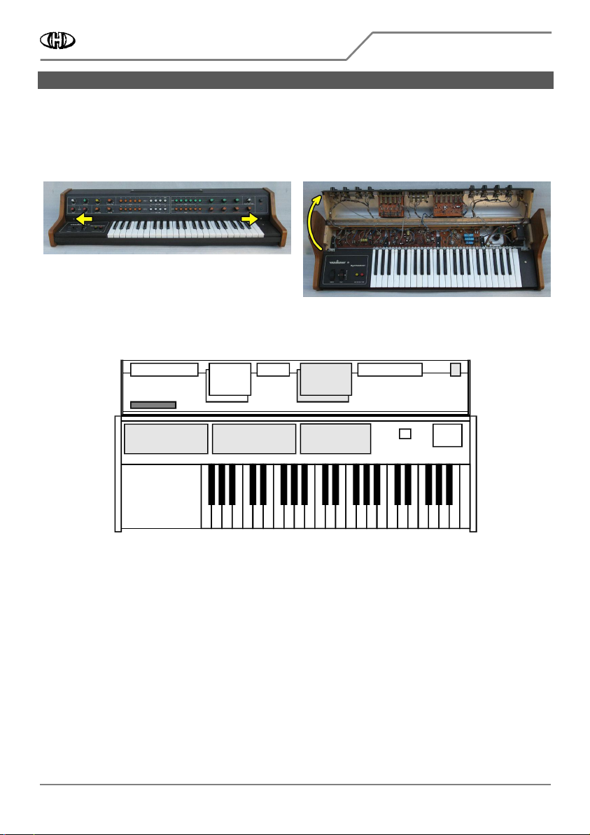
b) Drill two holes with diameter 16 mm and four holes with diameter 3,2 mm to the panel of the instrument as
shown on fig. 2.2.1. Use sharp drills and work carefully
work carefullywork carefully
work carefully so that the panel is not scratched and other parts of the
instrument are not damaged during the drilling (fig. 2.2.2)!
Fig. 2.2.1
Fig. 2.2.1Fig. 2.2.1
Fig. 2.2.1
Fig. 2.2.2
Fig. 2.2.2Fig. 2.2.2
Fig. 2.2.2
c) Clean the edge of the holes with small rasp or tip of bigger drill from both sides of the panel after the holes
are drilled.
d) Clean all metal sawdust and raspings from the inside of the instruments
Clean all metal sawdust and raspings from the inside of the instrumentsClean all metal sawdust and raspings from the inside of the instruments
Clean all metal sawdust and raspings from the inside of the instruments, they can cause short circuits or
serious electrical damage if they are left inside the instrument. Please clean the instrument carefully!
2.2.2
2.2.22.2.2
2.2.2
MIDI SOCKETS MOUNTING
MIDI SOCKETS MOUNTINGMIDI SOCKETS MOUNTING
MIDI SOCKETS MOUNTING
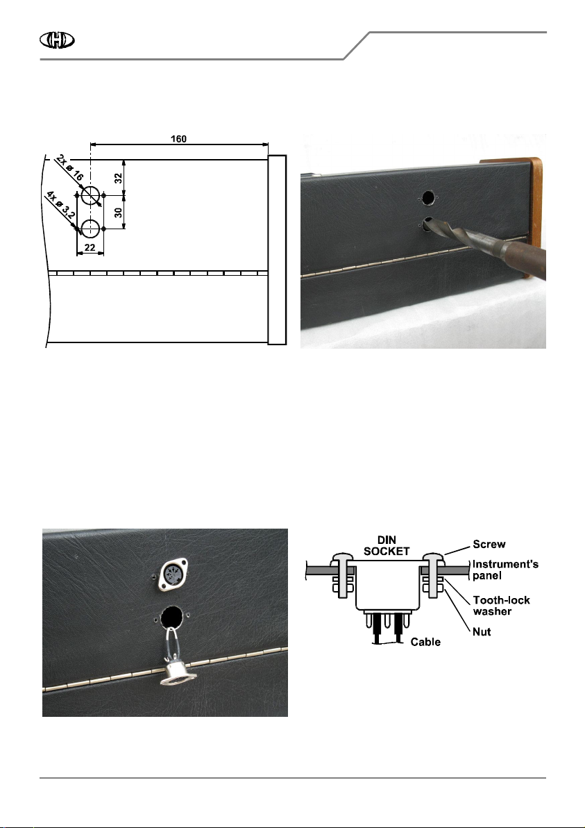
a) Pull flat connectors of MIDI cables through the 16 mm holes in the panel from outer side and insert the DIN
sockets of the cables into the holes (fig. 2.2.3). Both MIDI cables are identical and can be swapped.
b) Fix the DIN sockets to the panel using four screws, tooth-lock washers and nuts from the interface accessory
(fig. 2.2.4).
Fig. 2.2.3
Fig. 2.2.3Fig. 2.2.3
Fig. 2.2.3
Fig. 2.2.4
Fig. 2.2.4Fig. 2.2.4
Fig. 2.2.4

Vermona Synthesizer MIDI Interface
Vermona Synthesizer MIDI InterfaceVermona Synthesizer MIDI Interface
Vermona Synthesizer MIDI Interface
VS
VS VS
VS-
--
-MIDI
MIDIMIDI
MIDI Installation
Installation Installation
Installation Manual
Manual Manual
Manual
8
88
8-
--
-434 /
434 /434 /
434 / v. 2.00
v. 2.00 v. 2.00
v. 2.00
Copyright © 2022 CHD Elektroservis. All rights reserved.
No part of this publication may be reproduced in any form without the written permission of CHD Elektroservis.
7
7
7
7
Fig. 2.2.5
Fig. 2.2.5Fig. 2.2.5
Fig. 2.2.5
c) It is recommended to label the DIN sockets ("MIDI
IN", "MIDI THRU/OUT" for example) with self-adhesive
foil glued near the sockets (fig. 2.2.5).
2.3
2.32.3
2.3
INSTALLATION OF BUNCHED CABLES WITH
INSTALLATION OF BUNCHED CABLES WITH INSTALLATION OF BUNCHED CABLES WITH
INSTALLATION OF BUNCHED CABLES WITH
5
55
5-
--
-PIN CONNECTOR AND LED
PIN CONNECTOR AND LEDPIN CONNECTOR AND LED
PIN CONNECTOR AND LED
These cables (power supply voltages) will be connected to instrument’s power supply board (fig. 2.3.1). Used
solder lugs on the power supply board shows fig. 2.3.2.
Fig. 2.3.1
Fig. 2.3.1Fig. 2.3.1
Fig. 2.3.1
Fig. 2.3.2
Fig. 2.3.2Fig. 2.3.2
Fig. 2.3.2

Vermona Synthesizer MIDI Interface
Vermona Synthesizer MIDI InterfaceVermona Synthesizer MIDI Interface
Vermona Synthesizer MIDI Interface
VS
VS VS
VS-
--
-MIDI
MIDIMIDI
MIDI Installation
Installation Installation
Installation Manual
Manual Manual
Manual
8
88
8-
--
-434 /
434 /434 /
434 / v. 2.00
v. 2.00 v. 2.00
v. 2.00
Copyright © 2022 CHD Elektroservis. All rights reserved.
No part of this publication may be reproduced in any form without the written permission of CHD Elektroservis.
8
8
8
8
2.3.1
2.3.12.3.1
2.3.1
CONNECTION TO POWER SUPPLY BOARD
CONNECTION TO POWER SUPPLY BOARDCONNECTION TO POWER SUPPLY BOARD
CONNECTION TO POWER SUPPLY BOARD
a) Put the power supply bunched cables to instrument’s cover – add them under glazing sprig to original cables
(fig. 2.3.3).
Fig. 2.3.3
Fig. 2.3.3Fig. 2.3.3
Fig. 2.3.3
b) Solder the black wire Nr. 2 to ground potential – solder lug (2) GND (fig. 2.3.2).
c) Solder the yellow wire Nr. 3 to +20V supply voltage – solder lug (3) +20V. This lug is free by that time, no next
cable is connected to it (fig. 2.3.2).
d) Solder the red wire Nr. 4 to +12V supply voltage – solder lug (4) +12V (fig. 2.3.2).
e) Solder the blue wire Nr. 5 to -12V supply voltage – solder lug (5) -12V (fig. 2.3.2).
2.3.2
2.3.22.3.2
2.3.2
LED INDICATOR REPLACEMENT
LED INDICATOR REPLACEMENTLED INDICATOR REPLACEMENT
LED INDICATOR REPLACEMENT
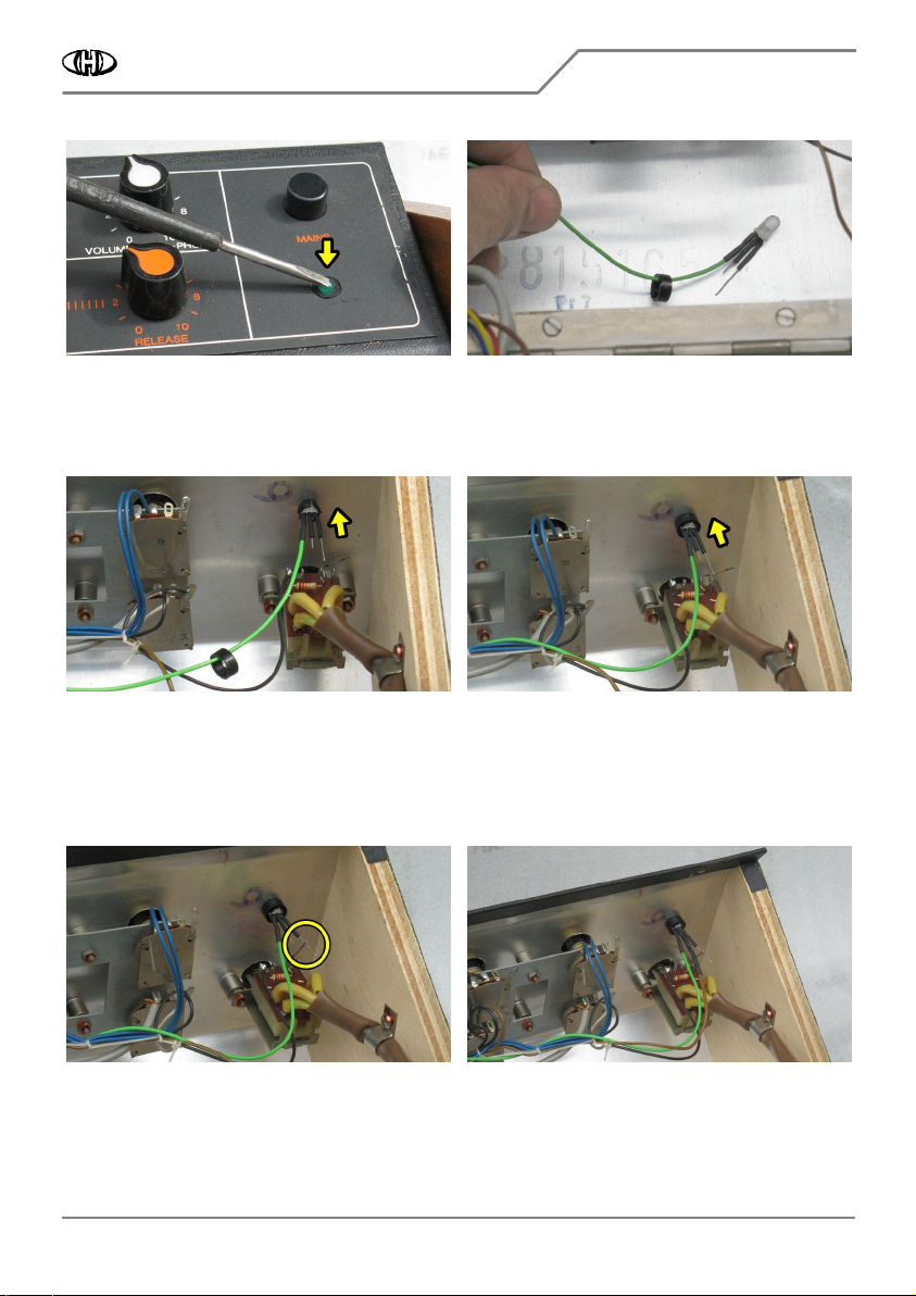
The original LED which indicates power-on status of the instrument has to be replaced with bi-color LED fixed to
wire Nr. 1 of power supply bunched cables. Procedure is as follows:
a) Unsolder leads of original LED (fig. 2.3.4).
b) Eject lock ring of LED holder with help of a screwdriver for example (fig. 2.3.5).
Fig. 2.3.4
Fig. 2.3.4Fig. 2.3.4
Fig. 2.3.4
Fig. 2.3.5
Fig. 2.3.5Fig. 2.3.5
Fig. 2.3.5
c) Remove the original LED from holder – push to its head from front side (fig. 2.3.6).
d) Pull the lock ring of the LED holder over the new bi-color LED (fig. 2.3.7).
Vermona Synthesizer MIDI Interface
Vermona Synthesizer MIDI InterfaceVermona Synthesizer MIDI Interface
Vermona Synthesizer MIDI Interface
VS
VS VS
VS-
--
-MIDI
MIDIMIDI
MIDI Installation
Installation Installation
Installation Manual
Manual Manual
Manual
8
88
8-
--
-434 /
434 /434 /
434 / v. 2.00
v. 2.00 v. 2.00
v. 2.00
Copyright © 2022 CHD Elektroservis. All rights reserved.
No part of this publication may be reproduced in any form without the written permission of CHD Elektroservis.
9
9
9
9
Fig. 2.3.6
Fig. 2.3.6Fig. 2.3.6
Fig. 2.3.6
Fig. 2.3.7
Fig. 2.3.7Fig. 2.3.7
Fig. 2.3.7
e) Insert the new LED into the holder (from inner side of the instrument’s panel) so that its two free leads will
be to right (fig. 2.3.8).
f) Fix the new LED by the overthrust of the lock ring on the holder (fig. 2.3.9).
Fig. 2.3.8
Fig. 2.3.8Fig. 2.3.8
Fig. 2.3.8
Fig. 2.3.9
Fig. 2.3.9Fig. 2.3.9
Fig. 2.3.9
g) Solder free outer lead of the new LED to jumper wire brought from resistor fixed on switch (fig. 2.3.10, 2.3.1).
h) Place heat-shrink insulation tube φ 2 mm (from the interface accessory) on brown cable (-20V from power
supply) unsoldered from original LED and solder the cable to middle lead of new LED. Overlap the connection
with the insulation tube and heat it (with a hot-flue pistol for example) until it shrinks tightly to the cable and
the LED’s lead (fig. 2.3.11, 2.3.1).
Fig. 2.3.10
Fig. 2.3.10 Fig. 2.3.10
Fig. 2.3.10
Fig. 2.3.11
Fig. 2.3.11 Fig. 2.3.11
Fig. 2.3.11
2.4
2.42.4
2.4
INSTALLATION OF BUNCHED CABLES WITH 7
INSTALLATION OF BUNCHED CABLES WITH 7INSTALLATION OF BUNCHED CABLES WITH 7
INSTALLATION OF BUNCHED CABLES WITH 7-
--
-PIN CONNECTOR
PIN CONNECTORPIN CONNECTOR
PIN CONNECTOR
These cables (control signals) will be connected to instrument’s VCO, VCF, VCA and EG boards (fig. 2.4.1). Used
solder lugs and pads on the boards shows figures 2.4.3 to 2.4.6.

Vermona Synthesizer MIDI Interface
Vermona Synthesizer MIDI InterfaceVermona Synthesizer MIDI Interface
Vermona Synthesizer MIDI Interface
VS
VS VS
VS-
--
-MIDI
MIDIMIDI
MIDI Installation
Installation Installation
Installation Manual
Manual Manual
Manual
8
88
8-
--
-434 /
434 /434 /
434 / v. 2.00
v. 2.00 v. 2.00
v. 2.00
Copyright © 2022 CHD Elektroservis. All rights reserved.
No part of this publication may be reproduced in any form without the written permission of CHD Elektroservis.
10
1010
10
Fig. 2.4.1
Fig. 2.4.1Fig. 2.4.1
Fig. 2.4.1
Fig. 2.4.2
Fig. 2.4.2Fig. 2.4.2
Fig. 2.4.2
Fig. 2.4.3
Fig. 2.4.3Fig. 2.4.3
Fig. 2.4.3

Vermona Synthesizer MIDI Interface
Vermona Synthesizer MIDI InterfaceVermona Synthesizer MIDI Interface
Vermona Synthesizer MIDI Interface
VS
VS VS
VS-
--
-MIDI
MIDIMIDI
MIDI Installation
Installation Installation
Installation Manual
Manual Manual
Manual
8
88
8-
--
-434 /
434 /434 /
434 / v. 2.00
v. 2.00 v. 2.00
v. 2.00
Copyright © 2022 CHD Elektroservis. All rights reserved.
No part of this publication may be reproduced in any form without the written permission of CHD Elektroservis.
11
1111
11
a) Add bunched cables to original cables – use original glazing sprig. Blue, green and yellow wires are in
instrument’s cover; black, red, and shielded wires are directed to bottom basis part of the instrument (pic.
2.4.2).
b) Solder shielded wire Nr. 1 (red – one wire of shielded twin-lead) to left lead of R25 resistor (near operational
amp IS1) on VCO board – pad (1) CV. Cleanse an oxyded layer on the resistor lead before soldering (fig. 2.4.3).
c) Solder shielded wire Nr. 3 (white – the other wire of shielded twin-lead) to UTS signal on VCO board – solder
lug (3) UTS (fig. 2.4.3).
d) Solder the black wire Nr. 2 (ground) to ground potential on VCO board – solder lug (2) GND (fig. 2.4.3).
e) Solder the red wire Nr. 7 to signal GATE on VCO board – solder lug (7) Gate (fig. 2.4.3).
Fig. 2.4.4
Fig. 2.4.4Fig. 2.4.4
Fig. 2.4.4
Fig. 2.4.5
Fig. 2.4.5Fig. 2.4.5
Fig. 2.4.5
Vermona Synthesizer MIDI Interface
Vermona Synthesizer MIDI InterfaceVermona Synthesizer MIDI Interface
Vermona Synthesizer MIDI Interface
VS
VS VS
VS-
--
-MIDI
MIDIMIDI
MIDI Installation
Installation Installation
Installation Manual
Manual Manual
Manual
8
88
8-
--
-434 /
434 /434 /
434 / v. 2.00
v. 2.00 v. 2.00
v. 2.00
Copyright © 2022 CHD Elektroservis. All rights reserved.
No part of this publication may be reproduced in any form without the written permission of CHD Elektroservis.
12
1212
12
f) Unsolder two blue wires from solder lug on EG board (fig. 2.4.4) and solder blue wire Nr. 4 (EG) of the signal
bunched cables to this lug.
g) Unsolder blue wire from solder lug on VCF board (fig. 2.4.5) and solder green wire Nr. 5 (VCF) of the signal
bunched cables to this lug.
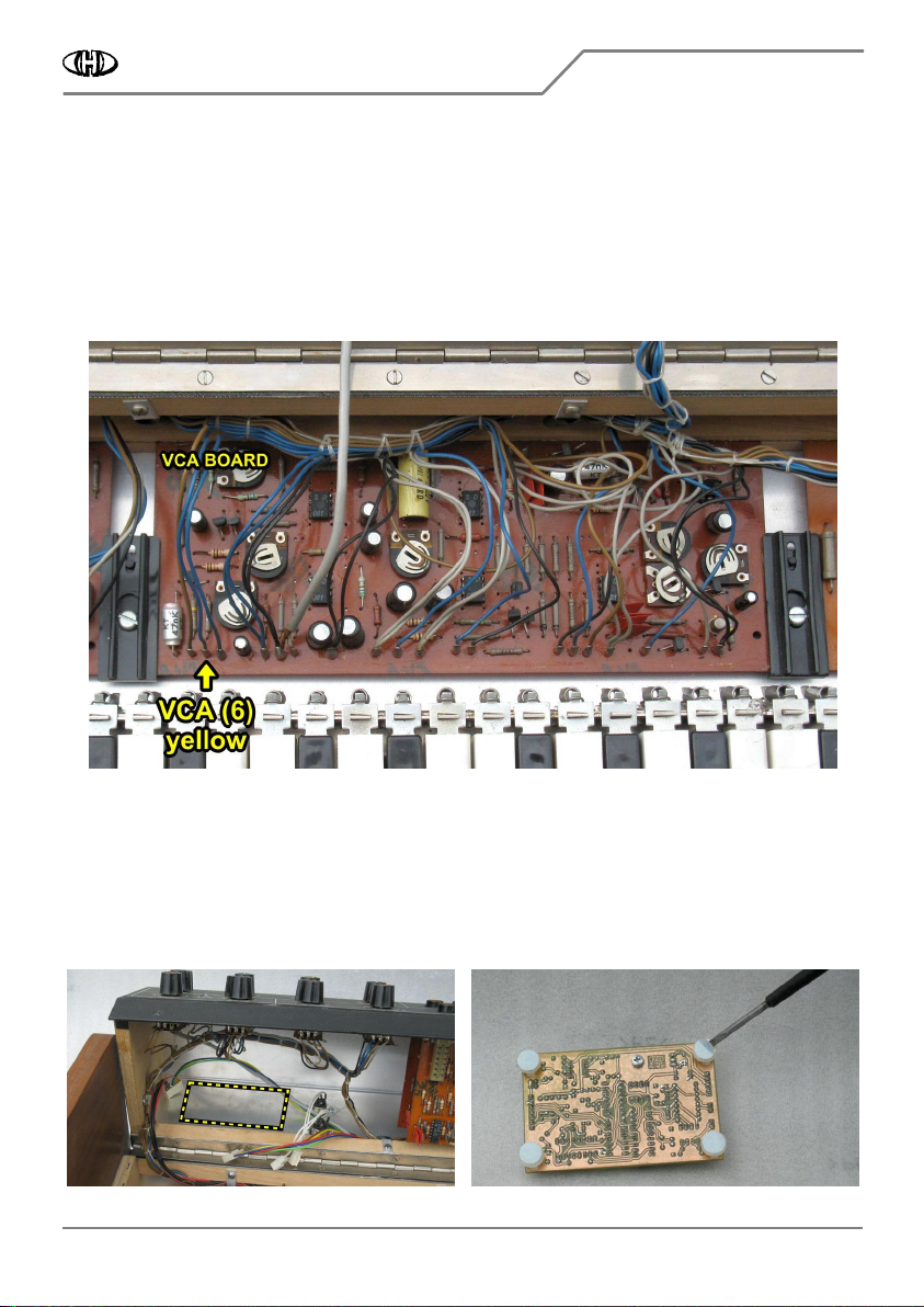
h) Unsolder blue wire from solder lug on VCA board (fig. 2.4.6) and solder yellow wire Nr. 6 (VCA) of the signal
bunched cables to this lug.
i) The original blue wires (which related EG, VCF, VCA boards) can be fully removed. Or they can be retained in
the instrument, but it is necessary to insulate them in this case so that no short occurs in the instrument.
Fig. 2.4.6
Fig. 2.4.6Fig. 2.4.6
Fig. 2.4.6
2.5
2.52.5
2.5
INTERFACE BOARD INSTALLATION
INTERFACE BOARD INSTALLATIONINTERFACE BOARD INSTALLATION
INTERFACE BOARD INSTALLATION
2.5.1
2.5.12.5.1
2.5.1
INTERFACE BOARD PLACEMENT
INTERFACE BOARD PLACEMENTINTERFACE BOARD PLACEMENT
INTERFACE BOARD PLACEMENT
a) The interface board will be placed on left side of the rear panel of the instrument (fig. 2.5.1).
b) Cleanse the part of rear panel inside of the instrument for the interface board placement (fig. 2.5.1). Use a
chemical cleaner to remove all dirt and grease.
Fig. 2.5.1
Fig. 2.5.1Fig. 2.5.1
Fig. 2.5.1
Fig. 2.5.2
Fig. 2.5.2 Fig. 2.5.2
Fig. 2.5.2
Vermona Synthesizer MIDI Interface
Vermona Synthesizer MIDI InterfaceVermona Synthesizer MIDI Interface
Vermona Synthesizer MIDI Interface
VS
VS VS
VS-
--
-MIDI
MIDIMIDI
MIDI Installation
Installation Installation
Installation Manual
Manual Manual
Manual
8
88
8-
--
-434 /
434 /434 /
434 / v. 2.00
v. 2.00 v. 2.00
v. 2.00
Copyright © 2022 CHD Elektroservis. All rights reserved.
No part of this publication may be reproduced in any form without the written permission of CHD Elektroservis.
13
1313
13
Fig. 2.5.3
Fig. 2.5.3Fig. 2.5.3
Fig. 2.5.3
c) Remove the protective foil form the self-adhesive
supports of the interface board (fig. 2.5.2).
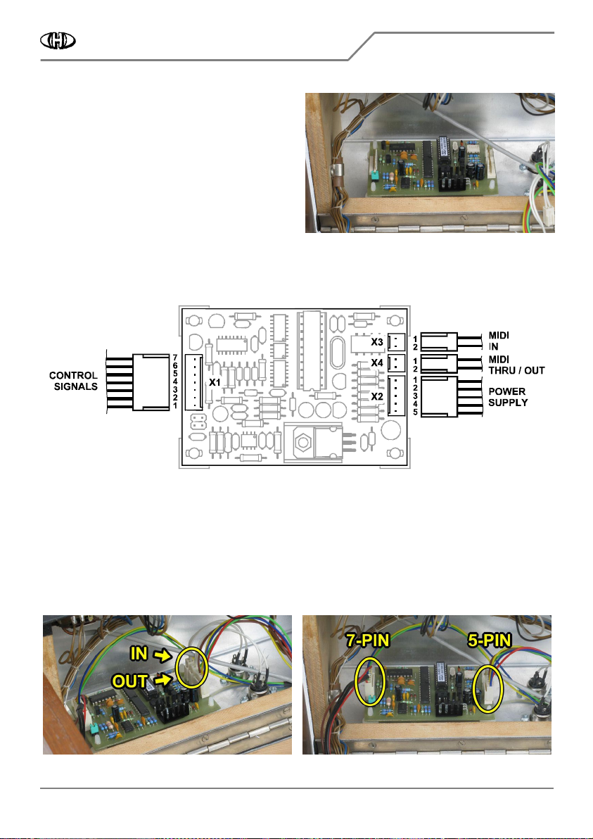
d) Attach the interface board to the instrument’s cover
so that the side with two 2-pin connector headers and
7-pin connector header points to right as shown on the
figure 2.5.3. Than fix the self-adhesive supports by
pressing down to the panel.
2.5.2
2.5.22.5.2
2.5.2
CONNECTION OF CABLES
CONNECTION OF CABLESCONNECTION OF CABLES
CONNECTION OF CABLES
The newly installed interface bunched cables will be plugged to the interface board as shown on figures 2.5.4 to
2.5.6.
Fig. 2.5.4
Fig. 2.5.4Fig. 2.5.4
Fig. 2.5.4
a) Plug two 2-pin connectors of the MIDI cables to X3 (“IN”) and X4 (“THRU / OUT”) plug heads. Orientation of
the connectors is given by the connector lock so they cannot be plugged reversely but be sure that the
connectors are not exchanged: MIDI input must be plugged to X3 head and MIDI output to X4 head (fig. 2.5.5).
b) Plug the 5-pin connector of the power supply cable to X2 plug head. Orientation of the connector is given by
the connector lock again (fig. 2.6.6).
c) Plug the 7-pin connector of the control signals cable to X1 plug head. Orientation of the connector is given by
the connector lock again (fig. 2.6.6).
Fig. 2.5.5
Fig. 2.5.5Fig. 2.5.5
Fig. 2.5.5
Fig. 2.5.6
Fig. 2.5.6 Fig. 2.5.6
Fig. 2.5.6
Vermona Synthesizer MIDI Interface
Vermona Synthesizer MIDI InterfaceVermona Synthesizer MIDI Interface
Vermona Synthesizer MIDI Interface
VS
VS VS
VS-
--
-MIDI
MIDIMIDI
MIDI Installation
Installation Installation
Installation Manual
Manual Manual
Manual
8
88
8-
--
-434 /
434 /434 /
434 / v. 2.00
v. 2.00 v. 2.00
v. 2.00
Copyright © 2022 CHD Elektroservis. All rights reserved.
No part of this publication may be reproduced in any form without the written permission of CHD Elektroservis.
1
4
141
4
14
2.5.3
2.5.32.5.3
2.5.3
SELECTION OF THE INSTRUMENT VERSION
SELECTION OF THE INSTRUMENT VERSIONSELECTION OF THE INSTRUMENT VERSION
SELECTION OF THE INSTRUMENT VERSION
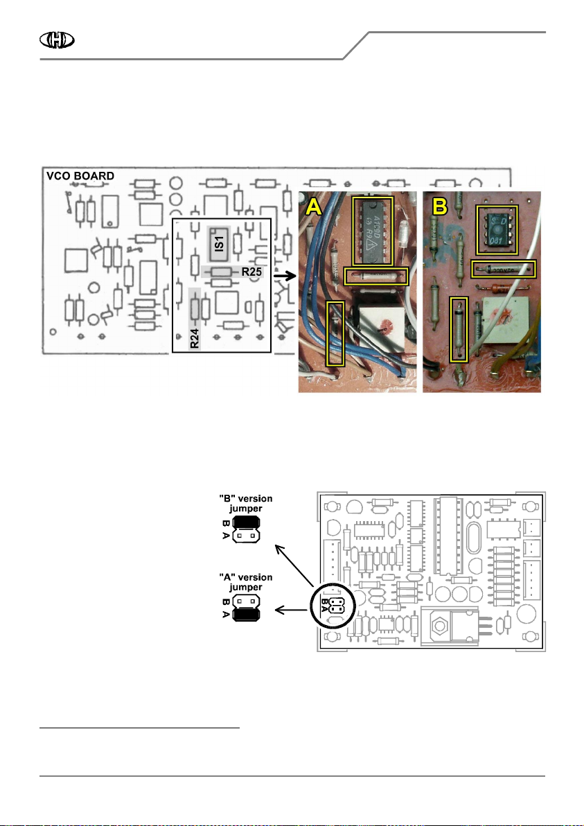
There is a jumper header on the interface board. Jumper (fom the interface accessory) must pe plugged on the
header in dependence on the instrument’s VCO board version. The version of VCO board can be easily
discovered pursuant type of operational amp on IS1 position and pursuant values of resistors R24 and R25 (fig.
2.5.7).
Fig. 2.5.7
Fig. 2.5.7Fig. 2.5.7
Fig. 2.5.7
The “A” version of VCO board is equipped by A109
1
11
1
type of operational amp (it has 14 pins) on position IS1 and
value of R24 and R25 resistors is 22 kΩ. The “B” version of VCO board is equipped by B081
2
22
2
type of operational
amp (it has 8 pins) on position IS1 and value of R24 and R25 resistors is 220 kΩ. Type of operational amp is
printed directly on its top side and values of the resistors can be measured with a multimeter for example.
Fig. 2.5.8
Fig. 2.5.8Fig. 2.5.8
Fig. 2.5.8
For the “A” version (IS1 = A109; R24,
R25 = 22kΩ), plug the jumper on
interface board to position “A” (fig.
2.5.8).
For the “B” version (IS1 = B081; R24,
R25 = 220kΩ), plug the jumper on
interface board to position “B” (fig.
2.5.8).
1
This is equivalent of more known µA709 type.
2
This is equivalent of more known TL081 type.
Vermona Synthesizer MIDI Interface
Vermona Synthesizer MIDI InterfaceVermona Synthesizer MIDI Interface
Vermona Synthesizer MIDI Interface
VS
VS VS
VS-
--
-MIDI
MIDIMIDI
MIDI Installation
Installation Installation
Installation Manual
Manual Manual
Manual
8
88
8-
--
-434 /
434 /434 /
434 / v. 2.00
v. 2.00 v. 2.00
v. 2.00
Copyright © 2022 CHD Elektroservis. All rights reserved.
No part of this publication may be reproduced in any form without the written permission of CHD Elektroservis.
15
1515
15
2.6
2.62.6
2.6
INSTRUMENT RE
INSTRUMENT REINSTRUMENT RE
INSTRUMENT RE-
--
-ASSEMBLY
ASSEMBLYASSEMBLY
ASSEMBLY
a) Turn the top cover back to its original position on the instrument and fix it two original screws and washers
(fig. 2.6.1). This is the reverse procedure of that described in the chapter 2.1.
Fig. 2.6.1
Fig. 2.6.1Fig. 2.6.1
Fig. 2.6.1
b) The installation of the VC-MIDI kit is now finished, the instrument is ready for use with MIDI control (fig.
2.6.2).
Fig. 2.6.2
Fig. 2.6.2Fig. 2.6.2
Fig. 2.6.2
Please read the user’s manual carefully before the MIDI interface usage so yo
Please read the user’s manual carefully before the MIDI interface usage so yoPlease read the user’s manual carefully before the MIDI interface usage so yo
Please read the user’s manual carefully before the MIDI interface usage so you understand all interface functions!
u understand all interface functions!u understand all interface functions!
u understand all interface functions!
Vermona Synthesizer MIDI Interface
Vermona Synthesizer MIDI InterfaceVermona Synthesizer MIDI Interface
Vermona Synthesizer MIDI Interface
VS
VS VS
VS-
--
-MIDI
MIDIMIDI
MIDI Installation
Installation Installation
Installation Manual
Manual Manual
Manual
8
88
8-
--
-434 /
434 /434 /
434 / v. 2.00
v. 2.00 v. 2.00
v. 2.00
Copyright © 2022 CHD Elektroservis. All rights reserved.
No part of this publication may be reproduced in any form without the written permission of CHD Elektroservis.
16
1616
16
3
33
3
INSTALLATION TIPS
INSTALLATION TIPSINSTALLATION TIPS
INSTALLATION TIPS
3.1
3.13.1
3.1
MIDI INPUT AND OUTPUT
MIDI INPUT AND OUTPUTMIDI INPUT AND OUTPUT
MIDI INPUT AND OUTPUT
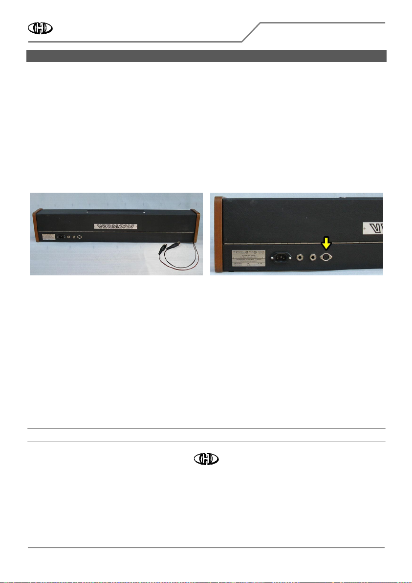
If you do not want to mechanically damage the panels of the instrument by drilling, you can use alternative
metod of the MIDI – IN / OUT sockets montage. You can lead out the MIDI cables through a slot on the
instrument cover (fig. 3.1.1). In that case, you will have to replace the delivered MIDI cables with another ones
equipped with cable type of the DIN sockets or plugs.
If you decide to install only MIDI-IN socket, the X4 connector (MIDI-THRU/OUT) on the interface board will
remain unused (see fig. 2.5.4).
In this case, you can replace the original headphones socket (on rear panel – fig. 3.1.2) with the MIDI-IN socket
so that a drilling to the instarument is not necessary.
Fig. 3.1.1
Fig. 3.1.1Fig. 3.1.1
Fig. 3.1.1
Fig. 3.1.2
Fig. 3.1.2Fig. 3.1.2
Fig. 3.1.2
All documents and support software are available at manufacturer’s web pages.
All documents and support software are available at manufacturer’s web pages. All documents and support software are available at manufacturer’s web pages.
All documents and support software are available at manufacturer’s web pages.
Vermona Synthesizer MIDI Interface
Model VS-MIDI, Nr. 8-434, ver. 2.00
Document: 843420_manual, rev. 1
Manufacturer: CHD Elektroservis, Czech Republic
www.chd-el.cz info@chd-el.cz
Other manuals for VS-MIDI 8-434
1
Table of contents


