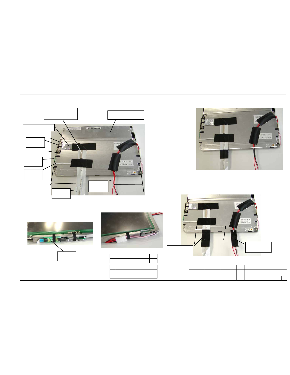
KLM-2556(a part of 200046362417 PCB
ASSY KLM-2417-91/2505-63)
500641041904
X-2100 JS SUPPORT L
KOC-C30660
500641041258
X-311/312 FSR
METAL KOC-C41000
500641041905
X-2100 JS SUPPORT R
KOC-C30662
500641041944
X-2100 EMI ANGLE JS KOC-C41410
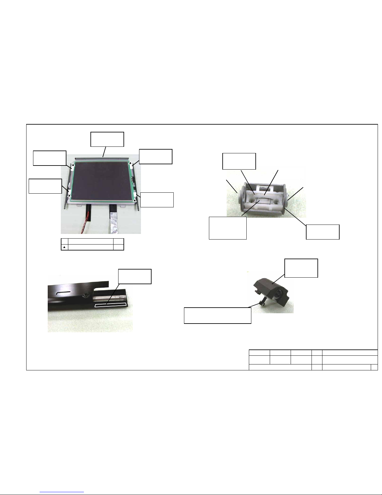
2100 JoystickASSY
500641041944
X-2100 EMI ANGLE JS KOC-C41410
500641041904
X-2100 JS SUPPORT
L KOC-C30660
KLM-2555(a part of
200046362417 PCB ASSY
KLM-2417-91/2505-63)
500475003450
HARNESS HNS-3450
C
500641041906
X-2160 JS SUPPORT
R KOC-C30661
500641041258
X-311/312 FSR
METAL KOC-C41000
500475003432
HARNESS
HNS-3432
500475002197
HARNESS HNS-2197
BOARD IN
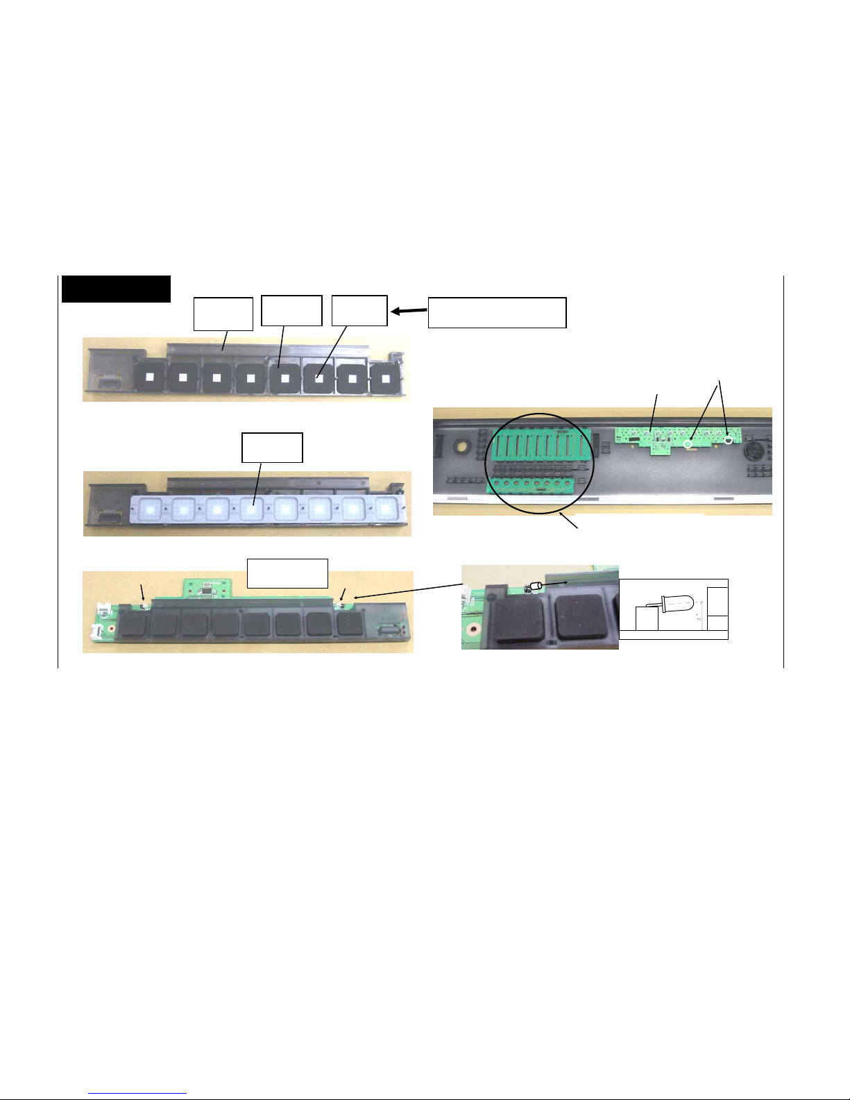
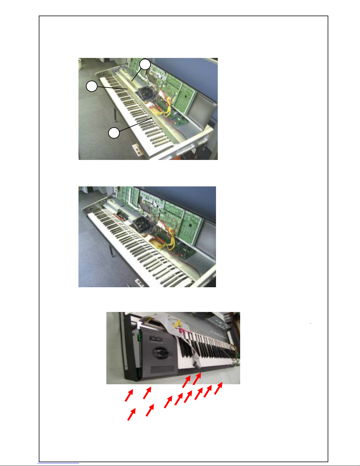
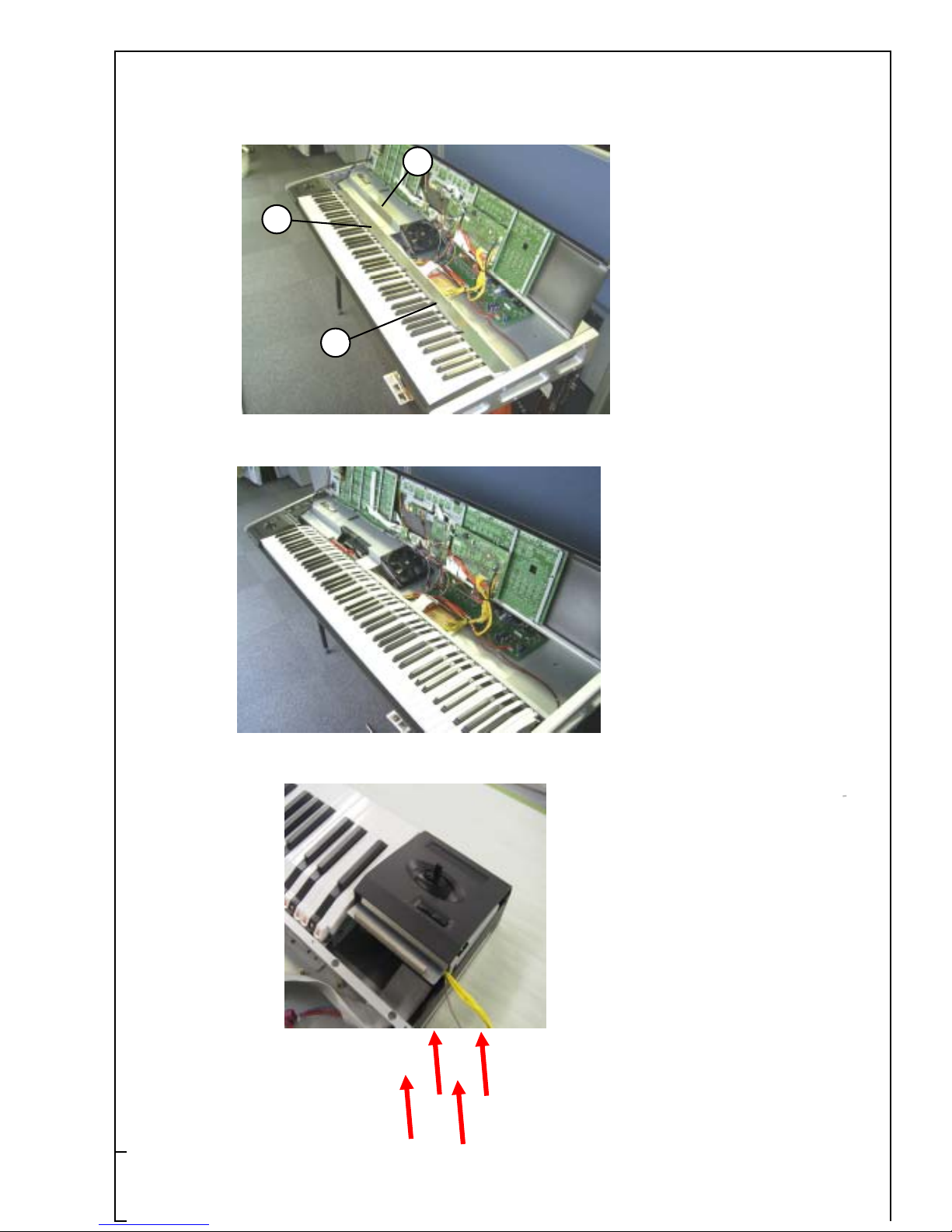
2100 JoystickASSY
X-2100 JSPanel ASSY X-2160 JSPanel ASSY
KLM-2556(a part of 200046362417
PCB ASSY KLM-2417-91/2505-63)