ChefLine 10 GUSTI User manual

P a g . 1 | 48
ISTRUZIONI ORIGINALI PER L’USO
Vetrine per gelato
ORIGINAL GENERAL INSTRUCTIONS
Ice Cream Cabinets
MODE D’EMPLOI ORIGINAL
Eiskremvitrinen
ORIGINAL ALLGEMEINE GEBRAUCHSANWEISUNGEN
Vitrines pour crème glacee
ISTRUCCIONES ORIGINALES DE UTILIZACION
Vitrina para helados

P a g . 2 | 48
ITALIANO
Vi ringraziamo per avere scelto uno dei nostri prodotti. Avete certamente fatto un buon investimento e siamo
sicuri che il nostro apparecchio ve lo proverà. Lo stesso è stato progettato accuratamente perch possa
fornire le massime prestazioni, nelle migliori condizioni di sicurezza e di economia. Durante il processo
produttivo sono stati inoltre eseguiti numerosi e severi controlli.
S
EGUIRE CON CURA LE DISPOSIZIONI SEGUENTI PER EVITARE RISCHI ALL
’
UTILIZZATORE
,
DANNI ALL
’
APPARECCHIO
O COMPROMISSIONE DELLE PRESTAZIONI
.
L
A NS
.
S
OCIETÀ DECLINA OGNI RESPONSABILITÀ NEL CASO LA FUNZIONALITÀ ORIGINALE DELL
’
APPARECCHIO
RISULTI ALTERATA DA MODIFICHE DI QUALSIASI TIPO
(
AGGIUNTA O ELIMINAZIONE DI PARTI ELETTRICHE O
MECCANICHE
)
O INOSSERVANZA DELLE ISTRUZIONI RIPORTATE NEL PRESENTE MANUALE
.
INDICE
1 – INSTALLAZIONE E AVVERTENZE p g. 3
2 – MOVIMENTAZIONE E TRASPORTO p g. 4
3 – CONDIZIONI AMBIENTALI p g. 4
4 – USO PREVISTO p g. 4
5 – MESSA IN SERVIZIO p g. 4
6 – CONSIGLI PER LA SALVAGUARDIA DELL’AMBIENTE p g. 5
7 – MANUTENZIONE PERIODICA p g. 6
8 – INCONVENIENTI E RIMEDI p g. 8
9 – COMANDI p g. 8
10 – MONTAGGIO LAVAPORZIONATORE p g. 10

P a g . 3 | 48
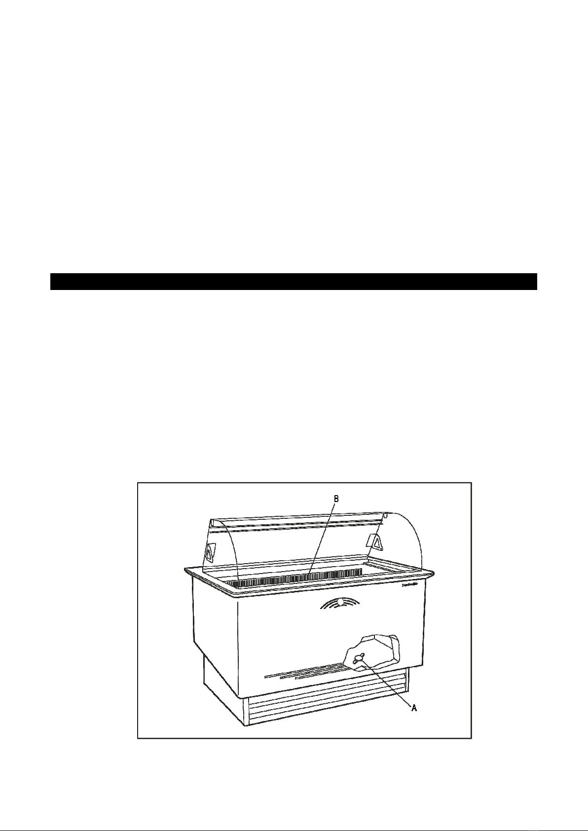
1 - INSTALLAZIONE e AVVERTENZE
1. Togliere l’imballo dall’apparecchio.
2. Controllare che l’apparecchio non sia stato danneggiato dal trasporto.
3. Togliere la pedana di legno.
4. Pulire l’apparecchio (interno/esterno) come specificato in MANUTENZIONE PERIODICA.
5. Non sistemare l’apparecchio all’aperto e non esporlo a pioggia: le condizioni ambientali esterne per il
regolare funzionamento dell’apparecchio sono specificate nella targhetta DATI TECNICI posta
sull’apparecchio.
6. L’apparecchio va sistemato su una superficie piana e per il buon funzionamento è indispensabile che lo
stesso sia perfettamente livellato;
7. Sistemare l’apparecchio in un luogo aerato, lontano da fonti di calore (termosifoni, cucine) e non esposto
ai raggi del sole. Per l’illuminazione della zona di posizionamento si suggerisce l’uso di lampade a
fluorescenza.
8. Lasciare una distanza di almeno 10 cm dalle pareti.
9. Non appoggiare nulla sopra l’apparecchio es. contenitori, piante, ecc. e lasciare uno spazio libero di
almeno 50 cm al di sopra dell’apparecchio.
10. L’apparecchio può essere dotato di serratura per la chiusura della/e porta/e (opzionale). In tal caso, le
chiavi di chiusura debbono essere tenute al di fuori della portata dei bambini.
11. Non toccare l’apparecchio in funzione a piedi nudi o con le mani bagnate
12. L’uso di questo apparecchio da parte di bambini o di persone affette da disabilità fisica, sensoriale,
mentale o motoria o persone che non hanno la conoscenza e l’esperienza necessarie potrebbe creare
situazioni pericolose. Le persone responsabili della loro sicurezza devono dare istruzioni esplicite o
controllare l'uso dell'apparecchio;
13. Assicurarsi che i bambini non giochino con l’apparecchio.
ALLACCIAMENTO ALLA RETE ELETTRICA
Controllare che la tensione effettiva di rete corrisponda a quella indicata sulla targhetta dati tecnici.
La linea/presa di alimentazione elettrica a cui deve essere allacciato il frigorifero deve essere
adeguatamente protetta e collegata all’impianto generale di terra secondo le norme vigenti (es. da
interruttore magnetotermico differenziale ad alta sensibilità In = 16 A , Id = 30 mA).
Un dispositivo di disconnessione unipolare deve essere presente sul lato dell'installazione con una
distanza dei contatti di almeno 3 mm.
LA MESSA A TERRA DELL’INSTALLAZIONE E’ UNA NORMA DI SICUREZZA ED INOLTRE E’
OBBLIGATORIA PER LEGGE. LA NS. SOCIETA’ AVENDO PREDISPOSTO, SECONDO LE NORME
IN VIGORE, QUESTO COLLEGAMENTO, DECLINA TUTTE LE RESPONSABILITA’ PER
EVENTUALI DANNI A PERSONE O COSE.
Non utilizzare assolutamente riduzioni, prese multiple o prolunghe ed assicurarsi che la portata elettrica
dell’impianto elettrico e le prese di alimentazione siano conformi alle norme vigenti e adeguate alla
potenza dell’apparecchio indicata sulla targa. In caso di dubbio, e per la verifica periodica della sicurezza
generale dell’impianto e degli utilizzatori, rivolgersi a personale professionalmente qualificato.
ATTENZIONE
NON BAGNARE LE PARTI DEL MOBILE OVE SIANO PRESENTI COMPONENTI ELETTRICHE.
NON FORZARE LE PARTI OVE SIANO PRESENTI COMPONENTI DEL CIRCUITO
FRIGORIFERO.
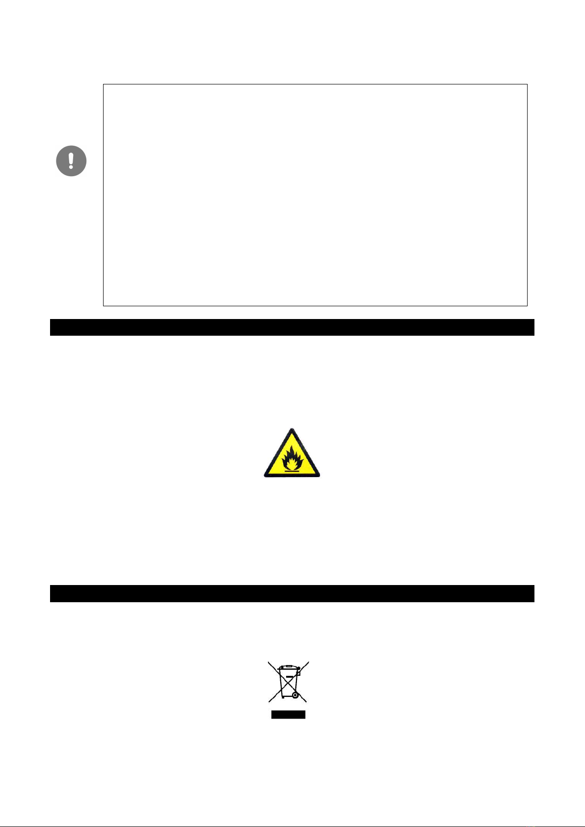
L’APPARECCHIO NON E’ IDONEO PER INSTALLAZIONE IN AMBIENTI CON PERICOLO DI
INCENDIO O DI ESPLOSIONE O SOTTOPOSTI A RADIAZIONI.
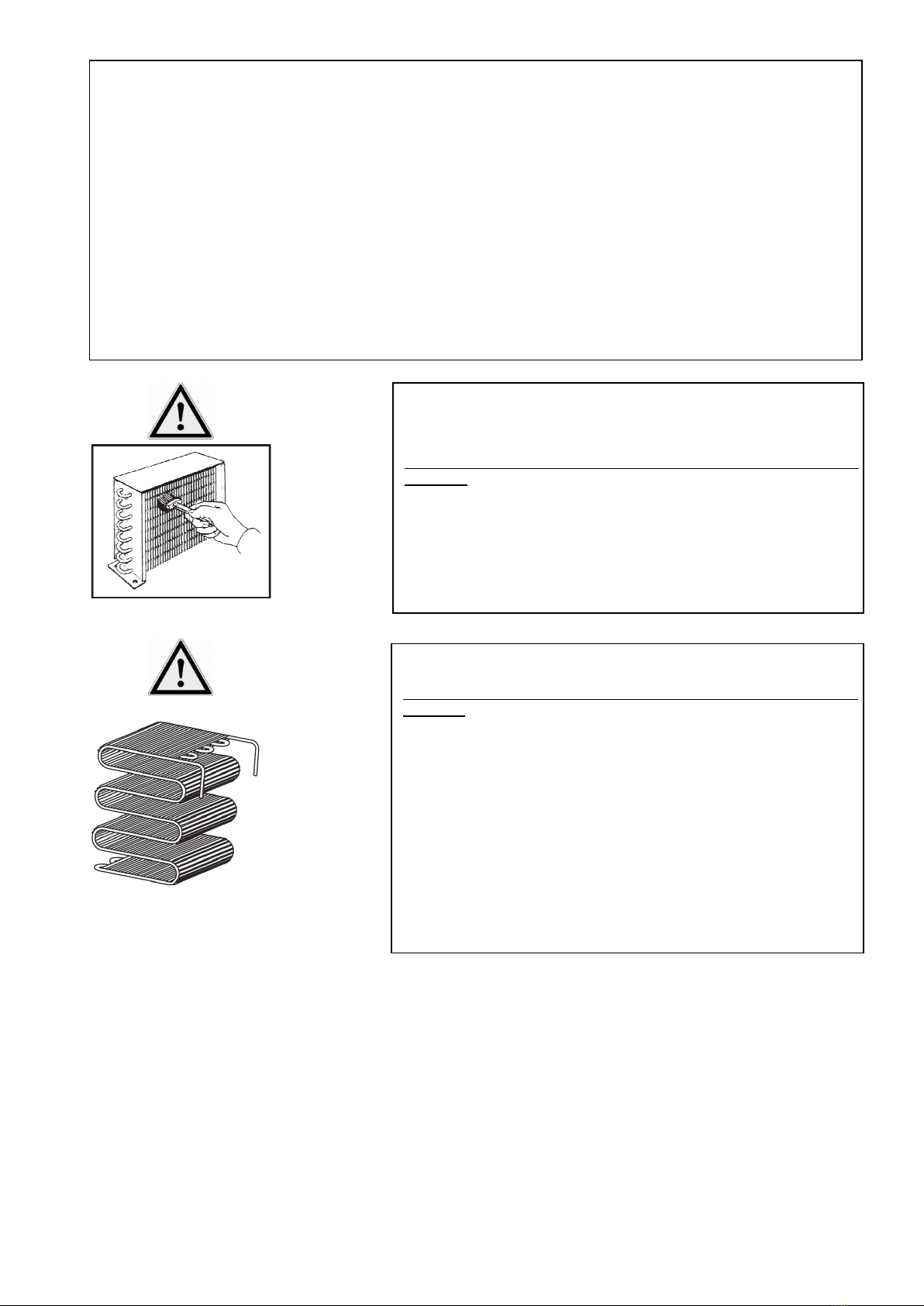
ATTENZIONE
IL SIMBOLO A LATO SIGNIFICA CHE L’OPERAZIONE E’ A CARICO DI TECNICI AUTORIZZATI
O PERSONA ESPERTA:
persona in possesso dell’addestramento tecnico e dell’esperienza necessaria a renderla consapevole dei
rischi cui è esposta nell’eseguire un compito e metterla un grado di adottare le misure necessarie a
rendere minimo l’eventuale danno a se stessa o ad altre persone.

P a g . 4 | 48
2 - MOVIMENTAZIONE E TRASPORTO
3 - CONDIZIONI AMBIENTALI
L’apparecchio è studiato per operare in specifiche condizioni climatiche ambientali. Questi limiti ambientali
non devono essere superati nell’utilizzo. Questi limiti sono posti nella targa DATI TECNICI.
Classe ambientale Temperatura massima
3 Max 25 °C
4 Max 30 °C
7 Max 35 °C
5 Max 43 °C
Per mantenere il clima ambiente nel luogo di installazione entro i limiti stabiliti nella targhetta dati tecnici può
essere necessario installare un impianto di condizionamento dell’aria. Tale impianto dovrebbe prevedere il
controllo dell’umidità relativa in quanto un’umidità eccessiva nuoce al buon funzionamento dell’apparecchio.
La posizione del mobile dovrebbe essere tale da limitare o evitare le correnti d’aria.
I mobili non devono essere installati vicino alle porte o in zone esposta forti movimenti d’aria provenienti,
per esempio, da bocchette di impianti di condizionamento, ventilazione o riscaldamento.
4 - USO PREVISTO
L’APPARECCHIO DEVE ESSERE ESCLUSIVAMENTE USATO PER LA CONSERVAZIONE, ESPOSIZIONE E VENDITA DI
GELATO MANTECATO IN APPOSITI CONTENITORI.
5 - MESSA IN SERVIZIO
Installare e posizionare l’apparecchio in modo che la spina di alimentazione sia facilmente accessibile.
Se l’apparecchio è stato fortemente inclinato, attendere almeno 3 ore prima della messa in funzione in modo
da permettere all’olio lubrificante di raccogliersi nel compressore, altrimenti la macchina può essere
danneggiata irreparabilmente.
Il livello sonoro è inferiore a 70 dB (A).
Dopo il collegamento, lasciare funzionare l’apparecchio vuoto per almeno due ore a luci spente, poi si può
procedere al caricamento del prodotto.
L’apparecchio imballato dispone di pedana
in legno adatta al sollevamento con carrelli
a forche o trans pallet.
L’apparecchio è dotato di ruote
unidirezionali.

P a g . 5 | 48
!! ATTENZIONE !!
Se sulla targa matricola e sull’imballo vedete il simbolo della fiamma significa che l’apparecchio utilizza come
gas refrigerante propano o isobutano. E’ quindi indispensabile accertarsi che tutti i tubi del circuito
refrigerante non siano danneggiati, prima di collegare l’apparecchio. Ogni 8 grammi di refrigerante, il locale
deve disporre di un volume minimo di 1mc di aria. La quantità di refrigerante dell’apparecchio è indicata
nella targa dati tecnici posta sull’apparecchio. In caso di perdita di refrigerante, evitare che fiamme libere o
fonti di accensione vengano a trovarsi in prossimità del punto di fuga. Fare attenzione a non danneggiare le
tubazioni del circuito refrigerante durante il posizionamento, l’installazione e la pulizia.
•Mantenere libere da ostruzioni le aperture di ventilazione nell’involucro dell’apparecchio o nella
struttura da incasso;
•Non usare dispositivi meccanici o altri mezzi per accelerare il processo di sbrinamento diversi da
quelli raccomandati dal costruttore;
•Non danneggiare il circuito refrigerante;
•Non usare apparecchi elettrici all’interno degli scomparti per la conservazione dei cibi
dell’apparecchio.
6 - CONSIGLI PER LA SALVAGUARDIA DELL ’AMBIENTE
Imb llo
Il materiale di imballo è riciclabile al 100% ed è contrassegnato con il simbolo del riciclaggio. Per lo
smaltimento seguire le normative locali. Il materiale di imballaggio (sacchetti di plastica, parti in polistirolo,
ecc.) deve essere tenuto fuori della portata dei bambini in quanto potenziale fonte di pericolo.
Prodotto
Ai sensi dell’art.13 del Decreto legislativo 25 luglio 2005, n.151 ”Attuazione delle
Direttive2002/95/CE,2002/96/CE e 2003/108/CE, relative alla riduzione dell’uso di sostanze pericolose nelle
apparecchiature elettriche ed elettroniche, nonch allo smaltimento dei rifiuti”
LA DISPOSIZIONE DEI PRODOTTI ALL’INTERNO DELL’APPARECCHIO NON DEVE MAI SUPERARE LE
INDICAZIONI DI LIVELLO MAX DI CARICO ALL’INTERNO DELLA VASCA (LINEE ROSSE).
NON INSERIRE MEDICINALI O ALTRI PRODOTTI DI GENERE FARMACEUTICO O SIMILARE.
NON CONSERVARE SOSTANZE ESPLOSIVE, CONTENITORI SOTTO PRESSIONE CON PROPELLENTE
INFIAMMABILE.
NON INTRODURRE ALL’INTERNO DEGLI APPARECCHI PRODOTTI AFFUMICATI O PRODOTTI CON
RESIDUI ACETOSI O PICCANTI, DAL MOMENTO CHE IL RAME DELL’EVAPORATORE SI POTREBBE
DANNEGGIARE.
IMMETTERE IL PRODOTTO NELL’APPARECCHIO, GIÀ ALLA TEMPERATURA DI CONSERVAZIONE;
PER IL CORRETTO FUNZIONAMENTO ED IL RISPARMIO DI ENERGIA IL COPERCHIO RIBALTABILE E LO
SPORTELLO VANO RISERVA DEVONO ESSERE RICHUSI IMMEDIATAMENTE DOPO L’UTILIZZO.
NON UTILIZZARE L’APPARECCHIO PER RAFFREDDARE ALIMENTI O BEVANDE (ES. SCIROPPI, THE,
FRUTTA, ECC) IN QUANTO PREGIUDICANO IL REGOLARE MANTENINENTO DEL GELATO.
CARICO MAX ESPOSIZIONE: MODELLO 10 GUSTI– 60 KG
MODELLO 13 GUSTI– 78 KG

P a g . 6 | 48
Il simbolo cestino barrato riportato sull’apparecchiatura o sulla sua confezione indica che il prodotto alla fine
della propria vita utile deve essere raccolto separatamente dagli altri rifiuti.
La raccolta differenziata della presente apparecchiatura giunta a fine vita è organizzata e gestita dal
produttore – distributore - rivenditore. L’utente che vorrà disfarsi della presente apparecchiatura dovrà
quindi contattare il produttore – distributore - rivenditore e seguire il sistema che questo ha adottato per
consentire la raccolta separata dell’apparecchiatura giunta a fine vita.
L’adeguata raccolta differenziata per l’avvio successivo dell’apparecchiatura dismessa al riciclaggio, al
trattamento e allo smaltimento ambientalmente compatibile contribuisce ad evitare possibili effetti negativi
sull’ambiente e sulla salute e favorisce il reimpiego e/o riciclo dei materiali di cui è composta
l’apparecchiatura.
Lo smaltimento abusivo del prodotto da parte del detentore comporta l’applicazione delle sanzioni
amministrative e penali previste dalla normativa vigente.
L’apparecchio contiene olio, gas refrigerante, parti in plastica, parti metalliche e vetro.
Attenzione l’isolamento poliuretanico utilizza come espandente CICLOPENTANO, una sostanza senza effetti
sull’ambiente, ma infiammabile.
7 - MANUTENZIONE PERIODICA
Qualsiasi intervento effettuato sull’apparecchio da parte dell’utente richiede assolutamente il distacco
preventivo della spina dalla presa di corrente.
Le parti meccaniche del frigorifero non necessitano di alcuna manutenzione periodica, ma per la lunga durata
dell’apparecchio è indispensabile un’accurata pulizia periodica (in funzione dell’uso):
•MOBILE ESTERNO: è sufficiente pulirlo con un panno morbido asciutto, nel caso di macchie resistenti
utilizzare acqua tiepida e detergenti neutri, successivamente sciacquare bene ed asciugare:
•PARTI IN ACCIAIO: lavare con acqua tiepida e saponi neutri, asciugare con un panno morbido ,evitare
pagliette o lana di acciaio che possono deteriorare la superficie.
•PARTI IN MATERIALE PLASTICO: lavare con acqua e saponi neutri. Sciacquare ed asciugare con un
panno morbido, evitare assolutamente l’uso di alcool, acetone e altri solventi che deterioreranno
permanentemente le superfici.
•PARTI IN VETRO: usare unicamente prodotti specifici, evitare l’uso di acqua che potrebbe depositare
calcare sulla superficie della e vetrata.

P a g . 7 | 48
PULIZIA CONDENSATORE ALETTATO (OGNI MESE)
PER CONDENSATORI COME DA FIGURA A LATO
Attenzione: l’operazione riportata nel seguito deve essere eseguita da un
tecnico specializzato.
Procedere periodicamente alla pulizia del condensatore alettato (se
presente) da impurità (polveri e detriti) che si accumulano tra le alette e
sulla superficie frontale, ostacolando una buona circolazione dell’aria. Un
condensatore sporco influisce negativamente sulla resa dell’impianto,
facendone scadere le prestazioni e determinando inutili consumi di
energia elettrica. Si può utilizzare un comune aspirapolvere o in
mancanza una spazzola a setole
CONDENSATORE A FILO SU TUBO (OGNI 6 MESI)
Attenzione: l’operazione riportata nel seguito deve essere eseguita da un
tecnico specializzato.
Il condensatore a tubi e fili, nell’esercizio in condizioni normali, non
presenta problemi di resa anche in presenza di un possibile accumulo di
polvere frontale.
È tuttavia importante che nel tempo l’accumulo non vada comunque a
occludere gli spazi tra i fili, in quanto in tal caso il basso ricambio d’aria
influisce negativamente sulle prestazioni dell’impianto provocando
surriscaldamenti ed inutili consumi di energia elettrica. È pertanto
necessario verificare con periodicità ameno annuale (comunque da
verificare in relazione alle condizioni ambiente) che il condensatore non
sia intasato da polvere o detriti.
In caso il condensatore risultasse sporco, procedere comunque alla
rimozione della polvere come descritto per la pulizia del condensatore
alettato, in quanto in ogni caso l’operazione riduce il consumo elettrico.
Per le operazioni di pulizia della vasca e procedere come segue:
1. Spegnere l’apparecchio e staccare la spina dalla presa di corrente.
2. Togliere il prodotto e i ripiani dalla vasca.
3. Lasciare la porta aperta ed aspettare che la temperatura interna della vasca sia uguale a quella ambiente.
4. Utilizzando un detersivo neutro procedere all’operazione di lavaggio e asciugatura della vasca interna con un
panno morbido;
5. Per facilitare lo scarico dell’acqua accumulata nel vano riserva togliere il tappo (A) avendo cura di riposizionarlo
ad operazione finita;
6. Non usare getti d’acqua nelle operazioni di pulizia, si possono danneggiare le parti elettriche.
7. Successivamente, riposizionare i ripiani e riattivare l’apparecchio e dopo circa un ora di funzionamento con le luci
spente è possibile caricare nuovamente i prodotti.
L’
APPARECCHIO È DOTATO DI SBRINAMENTO AUTOMATICO
:
VERIFICARE PERIODICAMENTE CHE GLI EVAPORATORI ALETTATI
(B)
NON SIANO
INTASATI DI GHIACCIO E NON VI SIANO RISTAGNI D
’
ACQUA NEL CANALE RACCOGLI GOCCE SOTTO L
’
EVAPORATORE

P a g . 8 | 48
8 - INCONVENIENTI e RIMEDI
L’ pp recchio non funzion :
• Controllare che la corrente arrivi regolarmente alla presa;
• Controllare che la spina sia bene inserita nella presa;
L temper tur intern non è sufficientemente b ss controll re che:
• L’apparecchio non si trovi vicino ad una fonte di calore;
• L’apparecchio non abbia la griglia frontale sia libera da ostruzioni;
• La ribaltina sia perfettamente chiusa;
• Il termostato sia posizionato correttamente;
• Il condensatore non risulti intasato o ostruito;
L’ pp recchio è rumoroso controll re che:
• Tutte le viti e i bulloni siano ben serrati;
• Qualche tubo o pala non sia in contatto con qualche altra parte dell’apparecchio;
• L’apparecchio sia ben livellato;
SE GLI INCONVENIENTI DOVESSERO CONTINUARE CONTATTARE IL PIÙ VICINO CENTRO DI
ASSISTENZA
9 - COMANDI
1 - T sto P : Utilizzato per l'impostazione del Set point e per la programmazione dei parametri di
funzionamento
2 - T sto DOWN/Aux : Utilizzato per il decremento dei valori da impostare e per la selezione dei
parametri.
3 - T sto UP/DEFROST : Utilizzato per l'incremento dei valori da impostare, per la selezione dei parametri
e per attivare sbrinamenti manuali.
4 - T sto U : Utilizzato per visualizzare le temperature misurate dalle sonde cella ed evaporatore (Pr1 e Pr2)
e l’ora dell’orologio interno (se presente).
5 - Led OUT : Indica lo stato dell'uscita compressore (o del dispositivo di controllo della temperatura) on
(acceso), off (spento) o inibita (lampeggiante)
SE IL CAVO DI ALIMENTAZIONE È DANNEGGIATO, ESSO DEVE ESSERE SOSTITUITO DAL
COSTRUTTORE O DAL SUO SERVIZIO DI ASSISTENZA TECNICA O COMUNQUE DA UNA PERSONA CON
QUALIFICA SIMILARE, IN MODO DA PREVENIRE OGNI RISCHIO.
LE RIPARAZIONI E LA SOSTITUZIONE DELLE LAMPADE DEVE ESSERE ESEGUITO DA PERSONALE
TECNICO QUALIFICATO CON L’APPARECCHIO SCOLLEGATO DALLA RETE ELETTRICA. SOSTITUIRE LE
LAMPADE CON LAMPADE IDENTICHE.
TUTTE LE OPERAZIONI DI MANUTENZIONE STRAORDINARIA DEVONO ESSERE EFFETTUATE DA
PERSONALE TECNICO QUALIFICATO.
LA MANOMISSIONE O SOSTITUZIONE NON AUTORIZZATA DI UNA O PIÙ PARTI
DELL’APPARECCHIATURA, L’ADOZIONE DI ACCESSORI CHE MODIFICANO L’USO DELLO STESSO E
L’IMPIEGO DI MATERIALI DI RICAMBIO DIVERSI DA QUELLI CONSIGLIATI, POSSONO DIVENIRE CAUSA
DI RISCHI DI INFORTUNIO.

P a g . 9 | 48
6 - Led DEF : Indica lo stato dello sbrinamento in corso (acceso) o lo stato di sgocciolamento
(lampeggiante)
.
7 - Led FAN : Indica lo stato dell'uscita ventole on (acceso), off (spento) o ritardata dopo sbrinamento
(lampeggiante)
8 - Led AUX : Indica lo stato dell’uscita AUX on (acceso), off (spento) o inibita (lampeggiante)
9 - Led AL : Indica lo stato di allarme on (acceso), off (spento) e tacitato o memorizzato (lampeggiante)
10 - Led SET : Indica l’ingresso nella modalità di programmazione e il livello di programmazione dei
parametri. Inoltre serve ad indicare lo stato di Stand-by.
11 - Led - : Indica che è in corso un allarme di bassa temperatura (acceso) o che è stato memorizzato un
allarme di bassa temperatura (lampeggiante).
12 - Led OK : Indica che non vi sono allarmi in corso
13 - Led + : Indica che è in corso un allarme di alta temperatura (acceso) o che è stato memorizzato un
allarme di alta temperatura (lampeggiante).
SEGNALAZIONI
Errore Motiv zione
E1
-E1
La sonda Pr1 può essere interrotta o in
cortocircuito,
E2
-E2 La sonda Pr2 può essere interrotta o in
cortocircuito,
EEPr Errore di memoria interna
Segn l zione
Motiv zione
od Ritardo all’accensione in corso
HI Allarme di massima temperatura in
corso
LO Allarme di minima temperatura in corso
IMPOSTAZIONE DEL SET POINT
Premere il tasto P quindi rilasciarlo e il display visualizzerà SP 1 (oppure SP 2 se in quel momento è attivo il
secondo set) alternato al valore impostato (vedi anche selezione del set point attivo).
Per modificarlo agire sui tasti UP per incrementare il valore o DOWN per decrementarlo.
L'uscita dal modo di impostazione del Set avviene alla pressione del tasto P.
SBRINAMENTI MANUALI
Per avviare un ciclo di sbrinamento manuale premere il tasto UP/DEFROST quando non si è in modo di
programmazione, e mantenerlo premuto per circa 5 secondi trascorsi i quali, se vi sono le condizioni, il led
DEF si accenderà e lo strumento realizzerà un ciclo di sbrinamento

P a g . 10 | 48
10 - MONTAGGIO LAVAPORZIONATORE (OPTIONAL)
1. Avvitare il supporto lavaporzionatore (A)
con il lavaporzionatore (B) utilizzando le
viti (C) sul retro del mobile.
2. Fissare il raccordo di carico acqua (3) con
valvola incorporata, posizionato come
nell’illustrazione, alla vaschetta (2) tramite
il dado di fissaggio (4).
3. Collegare il tubo in inox “troppo pieno” (7)
alla boccola (6) e fissarli alla vaschetta
con il dado (5).
4. Collegare il raccordo di carico acqua (3)
con il tubo di gomma ad un rubinetto e
riempire la vaschetta (2) di acqua pulita;
5. Collegare un tubo di gomma alla boccola
(6) e scaricare l’acqua in eccesso o sporca
(filtrata dalla copertura/divisorio (8) in un
lavabo.

Page 11 | 48
ENGLISH
Thank you for choosing one of our products. Your investment is valuable, and we are sure that our
equipment will prove it. Our product has been designed accurately, in order to provide the best performance
and the utmost safety and protection of the environment. During the production process, several test and
strict checks have been carried out successfully.
F
OLLOW THE INSTRUCTION CAREFULLY TO AVOID RISKS FOR THE OPERATOR
,
DAMAGE TO THE EQUIPMENT OR
IMPAIRMENT OF THE PERFORMANCE
.
O
UR
C
OMPANY CANNOT BE HELD LIABLE FOR TAMPERING WITH OR MODIFICATIONS APPLIED TO THE EQUIPMENT
(
ADDITION OR ELIMINATION OF ELECTRICAL OR MECHANICAL PARTS
)
OR DISREGARD OF INSTRUCTIONS
CONTAINED THEREIN
.
CONTENTS
1 - INSTALLATION AND WARNING NOTES p ge 12
2 - HANDLING AND TRANSPORT p ge 13
3 - ENVIRONMENTAL CONDITIONS p ge 13
4 - INTENDED USE p ge 13
5 - COMMISSIONING p ge 13
6 - SUGGESTIONS FOR THE ENVIRONMENTAL PROTECTION p ge 14
7 - PERIODIC MAINTENANCE p ge 15
8 - PROBLEMS AND REMEDIES p ge 17
9 - CONTROLS p ge 17
10 - ASSEMBLY OF UTENSILWASHER p ge 19

Page 12 | 48
1 - INSTALLATION nd WARNING NOTES
1. Remove the packaging from the equipment.
2. Check that the appliance has not been damaged during transport.
3. Remove the wood pallet.
4. Clean up the appliance (inside/outside) as specified in PERIODIC MAINTENANCE.
5. Do not place the appliance outdoors and do not expose it to rain: external environmental conditions
for the smooth operation of the appliance are specified in TECHNICAL DATA plate placed on the
appliance.
6. Put the appliance on a flat surface; for proper operation, the appliance shall be perfectly levelled:
7. Put the appliance in a ventilated place, far from heating sources (heaters, kitchens) and protected
from sum beams. For the lighting of the installation area, the use of fluorescent lights is
recommended.
8. Leave a space of at least 10 cm from walls.
9. Do not leave objects on the appliance, such as containers, plants, etc. and leave at least 50 cm of
free space above the appliance.
10. The appliance can be equipped with a lock for the door closing (optional). In this case, keep the lock
keys out of reach of children.
11. Do not touch the operating appliance with bare feet or wet hands.
12. The use of this appliance by children or people with physical, sensory, mental or physical disabilities
or people who do not have the knowledge and experience needed could create dangerous
situations. The people responsible for their safety must give explicit instructions or check the use of
the appliance;
13. Make sure that children do not play with the appliance.
CONNECTION TO THE ELECTRIC NETWORK
Check that the real mains voltage corresponds to the one specified in the technical data plate.
The power supply line/socket for the refrigerator connection shall be properly protected and connected
to the main ground system, according to the regulations in force (e.g. high-sensitivity magneto-thermal
differential switch In = 16 A , Id = 30 mA).
A single-pole disconnect device must be present on the side of the installation with a spacing of the
contacts of at least 3 mm.
THE APPLIANCE GROUND SYSTEM IS A SAFETY STANDARD AND MOREOVER, IT IS
REQUESTED BY THE LAW. OUR COMPANY HAS ARRANGED THIS CONNECTION ACCORDING
TO THE REGULATIONS IN FORCE; THEREFORE, THE COMPANY CAN NOT BE HELD LIABLE IN
CASE OF DAMAGE TO PEOPLE AND PROPERTY.
Do not use reducing devices, multiple plugs or cable extensions; ensure that the electric installation and
power supply plug capacity comply with the regulations in force and they are indicated for the
equipment power, according to the data specified in the plate. In case of doubt, for the purpose of
periodic check of general safety of equipment and users, contact only qualified and professional
technicians.
WARNING
DO NOT MOISTEN ANY PART OF THE BOX CONTAINING ELECTRIC COMPONENTS.
DO NOT FORCE ANY PART CONTAINING COMPONENTS OF THE REFRIGERATING CIRCUIT.
DO NOT INSTALL THE EQUIPMENT IN ATMOSPHERES SUBJECT TO RISK OF FIRE OR
WARNING
THIS SYMBOL INDICATES THAT ONLY AUTHORISED AND TRAINED TECHNICIANS SHALL
CARRY OUT THE OPERATION:
Trained and skilled operator, aware of risks involved and responsible of adopting all measures necessary
to minimise any possible damage to himself or other people.

Page 13 | 48
2 - HANDLING AND TRANSPORT
3 - ENVIRONMENTAL CONDITIONS
The appliance is designed to operate in specific environmental climatic conditions. These environmental
limits must not be exceeded in the use. These limits are indicated on the nameplate technicians.
Environmental class Maximum temperature
3 Max 25 °C
4 Max 30 °C
7 Max 35 °C
5 Max 43 °C
In order to keep the ambient climate in the installation place within the limits established in the technical
data plate, it can be necessary to install an air conditioning system. Such system should control the relative
humidity, as excessive humidity affects the good equipment operation.
The position of the box should limit or avoid the air flows.
Do not install the box close to doors or areas exposed to strong air flows, such as, for example, conditioning
system outlets, ventilation or heating openings.
4 - INTENDED USE
THE APPLIANCE SHOULD ONLY BE USED FOR THE PRESERVATION, DISPLAY AND SALE OF ICE CREAM WHIPPED INTO
SUITABLE CONTAINERS.
5 - COMMISSIONING
Install and place the appliance in such a way that the power plug is easily accessible.
If the appliance has been strongly inclined, wait for at least 3 hours prior to commissioning in order to allow
the lubricating oil to collect in the compressor, otherwise the machine may be damaged irreparably.
The sound level is less than 70 dB (A).
After connection, operate the equipment empty for at least two hours with lights off, then proceed and load
the products.
The appliance is packed on a wood pallet
suitable for lifting with forklift trucks or
pallet truck.
The appliance is equipped with single-
direction wheels.

Page 14 | 48
!! WARNING !!
If you notice the symbol of the flame on the serial number plate and on the packaging, this means that the
appliance uses gas propane or isobutane as refrigerant. It is therefore essential to make sure that all pipes
of the refrigerating circuit are not damaged, before you connect the appliance. Every 8 grams of refrigerant,
the room must have a minimum volume of 1 cubic meter of air. The amount of refrigerant in the appliance is
indicated on the technical data plate placed on the appliance. In the event of a refrigerant leak, avoid that
open flames or ignition sources are located in the vicinity of the escape point. Be careful not to damage the
pipes of the refrigerant circuit during the positioning, installation and cleaning.
• Keep the ventilation openings in the housing of the appliance or in the in-built structure free from
obstruction;
• Do not use mechanical devices or other means to accelerate the process of defrosting other than
those recommended by the manufacturer;
• Do not damage the refrigerant circuit;
• Do not use electrical devices inside the compartments for the preservation of the foods of the
appliance.
6 - SUGGESTIONS FOR THE ENVIRONMENTAL PROTECTION
P ck ging
The packaging material is 100% recyclable and is marked with the symbol of recycling. For disposal, follow
the local regulations. The packaging material (plastic bags, parts in polystyrene, etc.) must be kept out of
reach of children, as it is potential source of hazard.
Product
Within the meaning of art.13 of the L. Decree of 25 July 2005, no. 151 "Implementation of Directives
2002/95/EC, 2002/96/EC and 2003/108/EC, relating to the reduction of the use of certain hazardous
substances in electrical and electronic appliances, as well as the disposal of waste”
THE ARRANGEMENT OF THE PRODUCTS INSIDE THE APPLIANCE MUST NEVER EXCEED THE LEVEL
INDICATIONS MAX OF THE LOAD INSIDE THE CONTAINER (RED LINES).
DO NOT STORE MEDICAL PRODUCTS OR OTHER PHARMACEUTICAL PRODUCTS OR SIMILAR.
DO NOT STORE EXPLOSIVE SUBSTANCES, CONTAINERS UNDER PRESSURE WITH FLAMMABLE
PROPELLANT.
NOT TO INTRODUCE INSIDE THE APPLIANCE ANY SMOKED PRODUCTS OR PRODUCTS WITH SOUR OR
SPICY RESIDUES, AS THE COPPER OF THE EVAPORATOR MAY BE DAMAGED.
INTRODUCE THE PRODUCT IN THE APPLIANCE, ALREADY AT THE PRESERVATION TEMPERATURE;
FOR THE CORRECT OPERATION AND ENERGY SAVINGS, THE HINGED LID AND THE RESERVE DOOR
COMPARTMENT MUST BE CLOSED IMMEDIATELY AFTER USE.
DO NOT USE THE APPLIANCE TO COOL DOWN FOODS OR BEVERAGES (E.G. SYRUPS, TEA, FRUIT,
ETC.) AS THEY AFFECT THE REGULAR MAINTAINING OF ICE CREAM.
MAX DISPLAY LOAD: MODEL 10 FLAVOURS - 60 KG
MODEL 13 FLAVOURS - 78 KG

Page 15 | 48
The crossed-out dustbin symbol reported on the appliance or on its packaging indicates that this product, at
the end of its useful life, must be disposed of separately from other waste.
The waste sorting of this appliance, at the end of its useful life, is organized and managed by the
manufacturer - distributor - seller. The user who wants to dispose of this appliance should therefore contact
the manufacturer - distributor - seller and follow the system that this latter has adopted for waste sorting of
this appliance, at the end of its useful life.
The appropriate waste sorting for the recycling of the disposed appliance, treatment and environmentally
compatible disposal helps to avoid any possible adverse effects on the environment and on health and
promotes reuse and/or recycling of the materials of which the appliance is composed of.
Illegal disposal of the product by the user involves the application of administrative and criminal penalties
provided for by the legislation in force.
The appliance contains oil, refrigerant gas, plastic parts, metal parts and glass.
Warning! The polyurethane insulation uses CYCLOPENTANE as insulating foam, a substance without effects
on the environment, but flammable.
7 - PERIODIC MAINTENANCE
Before every intervention on the appliance by the user, disconnect the power supply plug.
The refrigerator mechanical parts do not require any periodic maintenance, but for a long-lasting life of the
appliance, periodic cleaning is fundamental (in function of the use):
• EXTERNAL FURNITURE: just clean it up with a dry soft cloth, in case of resistant spots, use lukewarm
water and neutral detergents, then rinse well and dry.
• PARTS IN STEEL: wash with lukewarm water and neutral soaps, dry with a soft cloth, do not use steel
wool, as it can damage the surface.
• PARTS MADE OF PLASTIC MATERIAL: wash with water and neutral soap. Rinse well and dry with a
soft cloth, do not use alcohol, acetone and other solvents, as they can damage the surface permanently.
• PARTS IN GLASS: use only specific products, do not use water, as it can build limestone on the glass
surface.

Page 16 | 48
FINNED CONDENSER CLEANING (EVERY MONTH)
FOR CONDENSERS AS IN THE FIGURE ON THE SIDE
Caution: only qualified technicians are allowed to carry out this
operation.
Clean regularly the finned condenser (if any) from impurit
ies (dust and
debris) that accumulate between the fins and on the front surface,
hindering a good air circulation. A clogged condenser negatively affects
the efficiency of the system, reducing the performance and causing
unnecessary power consumption. You can use a common vacuum
cleaner or a brush with bristles.
WIRE CONDENSER ON TUBE (EVERY 6 MONTHS)
Caution: the operation described below must be performed by a trained
technician.
The tube and wire condenser operating in normal conditions, does not
present any problems of performance, even in the presence of a possible
accumulation of dust in the front.
It is however important that over time the accumulation does not occlude
the spaces between the wires, since in this case the low exchange of air
negatively affects the performance of the appliance, causing overheating
and unnecessary power consumption. It is therefore necessary to check
at least once a year (still to be checked in relation to ambient conditions)
that the condenser is not clogged with dust or debris.
In case the condenser is dirty, proceed with the removal of dust as
described for the cleaning of the finned condenser, since in any case the
operation reduces the electrical consumption
.
For the container cleaning, proceed as follows:
8. Switch off the appliance and disconnect the plug from power supply.
9. Take the products and the shelves out of the container.
10. Leave the door open and wait until the container temperature corresponds to the outside temperature.
11. Wash and dry the internal container with a cloth and neutral detergent.
12. In order to facilitate the drainage of water accumulated in the reserve compartment, remove plug (A) taking care
to reposition it once completed the operation;
13. Do not use water jets for cleaning, as they can damage the electric parts.
14. Then, put the shelves back to their position and connect the appliance; after one hour of operation with lights
switched off, load the products.
T
HE APPLIANCE IS EQUIPPED WITH AUTOMATIC DEFROSTING
:
PERIODICALLY CHECK THAT THE FINNED EVAPORATORS
(B)
ARE NOT CLOGGED WITH
ICE AND THERE IS NO WATER STAGNATION IN THE DROP COLLECTION CHANNEL BELOW THE EVAPORATOR
.

Page 17 | 48
8 - PROBLEMS nd REMEDIES
The ppli nce does not work:
• Check that power is properly supplied through the plug;
• Check that the plug is properly plugged in the socket;
Intern l temper ture is not cold enough, check th t:
• The appliance is not close to any heating source;
• The appliance front grid is free from any obstructions;
• The door is properly closed;
• The thermostat is properly into position;
• The condenser is not clogged or obstructed;
The ppli nce is noisy, check th t:
• All screws and nuts are properly tightened;
• Any tube or blade is not in contact with any other part of the appliance;
• The appliance is well levelled;
IN CASE OF PERSISTENT PROBLEMS, CONTACT THE AFTER-SALES SERVICE NEAREST TO YOU
9- CONTROLS
1 - P Key : Used for the setting of the set point and for the programming of the operating parameters
2 - DOWN/Aux Key : Used to decrease the values to be set up and to select the parameters.
3 - UP/DEFROST Key : Used to increase the values to be set, to select the parameters and to enable
manual defrosting.
4 - U Key : Used to display the temperatures measured by the cell and evaporator sensors (Pr1 and Pr2)
and the internal clock time (if any).
5 - OUT Led : Indicates the status of the compressor outlet (or of the temperature control device) on (ON),
off (OFF) or disabled (flashing)
6 - DEF Led : Indicates the status of the defrost in progress (on) or status of dripping (flashing)
.
7 - FAN Led : Indicates the status of the fan output on (ON), off (OFF) or delayed after defrosting
(flashing)
8 - AUX Led : Indicates the status of AUX outlet on (ON), off (OFF) or disabled (flashing)
IN CASE THE SUPPLY CABLE IS DAMAGED, THE MANUFACTURER OR THE AFTER-SALES SERVICE, OR
QUALIFIED TECHNICIAN SHALL REPLACE IT, IN ORDER TO PREVENT ANY POSSIBLE RISK.
THE LAMP REPAIR AND REPLACEMENT SHALL BE CARRIED OUT BY QUALIFIED TECHNICIANS, WITH
POWER SUPPLY DISCONNECTED. REPLACE WITH IDENTICAL LAMPS.
ONLY QUALIFIED TECHNICIANS SHALL CARRY OUT THE EXTRAORDINARY MAINTENANCE
INTERVENTIONS.
TAMPERING WITH OR UNAUTHORISED REPLACEMENT OF ONE OR MORE PARTS OF THE APPLIANCE,
THE USE OF ACCESSORIES WHICH MODIFY THE OPERATION OF THE APPLIANCE AND THE USE OF
SPARE PARTS OTHER THAN THOSE RECOMMENDED MAY BECOME THE CAUSE OF ACCIDENT RISKS.

Page 18 | 48
9 - AL Led : Indicates the status of alarm on (ON), off (OFF) and silenced or stored (flashing)
10 - SET Led : Indicates the input in the programming mode and the level of programming of the
parameters. It also indicates the status of Stand-by.
11 - - Led : Indicates that there is an ongoing alarm for low temperature (on) or that an alarm for low
temperature has been stored (flashing).
12 - OK Led : Indicates that there are no alarms in progress
13 - + Led : Indicates that there is an ongoing alarm for high temperature (on) or that an alarm for high
temperature has been stored (flashing).
SIGNALS
Error Re son
E1
-E1
The Pr1 sensor may be interrupted or in short
circuit,
E2
-E2 The Pr2 sensor can be interrupted or in short
circuit,
EEPr Error in internal memory
Sign l Re son
od Delay at start up in progress
HI Alarm of max temperature in progress
LO Alarm of min temperature in progress
SETTING THE SET POINT
Press the P key, then release and the display will show SP 1 (or SP 2 if at that moment the second set is
activated) alternating with the set value (see also selection of the set point activated).
To change it, use the UP keys to increase the value or DOWN to lower it.
Exit from the Set setting mode is possible by pressing the P key.
MANUAL DEFROSTING
To start manual defrost cycle, press UP/DEFROST when not in programming mode, and hold for
approximately 5 seconds after which, if the conditions are met, the DEF led will light up and the appliance
will start a defrost cycle.

Page 19 | 48
10 - ASSEMBLY OF UTENSILWASHER (OPTIONAL)
1. Screw the utensilwasher support (A) to
the utensilwasher (B) using the screws
(C) on the rear of the cabinet.
2. Secure the water load fitting (3) with in-
built valve, positioned as shown in the
figure, to the container (2) via the
mounting nut (4).
3. Connect the "overflow" tube in stainless
steel (7) to the bush (6) and fix them to
the container with the nut (5).
4. Connect the water load fitting (3) with the
rubber hose to a tap and fill the container
(2) with clean water;
5. Connect a rubber hose to the bush (6)
and drain the excess or dirty water
(filtered from the cover/partition (8) to a
washbasin.

Page 20 | 48
FRANÇAIS
Merci d'avoir choisi l'un de nos produits. Vous avez certainement fait un bon investissement et nous sommes
certains que notre appareil vous le prouvera.
L’appareil a t soigneusement conçu pour pouvoir fournir une performance maximale, dans les meilleures
conditions de s curit et d' conomie.
De nombreux et rigoureux contrôles ont galement t effectu s au cours du processus de production.
R
ESPECTEZ SCRUPULEUSEMENT LES DISPOSITIONS SUIVANTES POUR ÉVITER TOUS RISQUES POUR L
'
UTILISATEUR
,
TOUS DOMMAGES À L
'
APPAREIL OU TOUTES PERTES DE PERFORMANCES
.
N
OTRE
S
OCIÉTÉ DÉCLINE TOUTE RESPONSABILITÉ SI LA FONCTIONNALITÉ D
'
ORIGINE DE L
'
APPAREIL EST ALTÉRÉE
PAR TOUT TYPE DE MODIFICATION
(
AJOUT OU SUPPRESSION DE COMPOSANTS ÉLECTRIQUES OU MÉCANIQUES
)
OU
PAR LE NON
-
RESPECT DES INSTRUCTIONS DONNÉES DANS CE MANUEL
.
INDEX
1 - INSTALLATION ET AVERTISSEMENTS p ge 21
2 – DEPLACEMENT ET TRANSPORT p ge 22
3 - CONDITIONS ENVIRONNEMENTALES p ge 22
4 - UTILISATION PRÉVUE p ge 22
5 - MISE EN SERVICE p ge 22
6 - CONSEILS POUR LA PROTECTION DE L'ENVIRONNEMENT p ge 23
7 - ENTRETIEN PÉRIODIQUE p ge 24
8 - PROBLÈMES ET REMEDES p ge 26
9 - CONTROLES p ge 26
10 - ASSEMBLAGE DU LAVE-CUILLERES p ge 28
This manual suits for next models
1
Table of contents
Languages:
Popular Commercial Food Equipment manuals by other brands

ITW
ITW E50I77 operating instructions

Metos
Metos 700 Series Installation and operation manual

Vollrath
Vollrath Stoelting O431 Service manual

Diamond
Diamond DH Series user manual

Marshall Amplification
Marshall Amplification DH5F-333WND owner's manual

Electrolux
Electrolux N7E Installation and operating manual

Omcan
Omcan FW-CN-0905 instruction manual

INTERNATIONAL CARBONIC
INTERNATIONAL CARBONIC Lil'Fella Installation and service manual

Metos
Metos 051R Installation, Utilization and Maintenance Manual

Inoksan
Inoksan PDE303 instruction manual

Encore
Encore Hartco ACE 4000 Series operating manual

Vulcan-Hart
Vulcan-Hart VL Series Service manual