Chekman TK-3211 User manual
TK-3211,TK-3212A를 구입해 주신 여러분께 감사드립니다.
본 제품은 계측기 전문생산업체인 본사가 최신 기술과 현대감각의 디자인으로 개발한
신제품으로 사용하시기 전에 설명서를 잘 읽어보시고 이용하시기 바랍니다.
We thank you very much for your purchasing
This model is a most reliable, high precision instrument, designed by our
excellent technology. Before you use your new instrument, please read this
INSTRUCTION MANUAL completely and familiarize yourself thoroughly with
all functions and connections.
POCKET DIGITAL MULTIMETER
TK-3211 , TK-3212A.
측정시 주의 사항 - Warning Instruction for Safe Use
본 제품을 안전하게 사용하기 위해서는 아래의 사항을 준수하십시오.
1. 1kVA를 초과하는 회로에서는 본 제품을 사용하지 마십시오.
2. AC30Vrms(42.4V peak), DC60V이상 측정 할 때는 특별히 주의하여 측정
하십시오.
3. 최대 입력전압을 초과해서 측정하지 마십시오.
4. 최대 허용전압을 초과하는 순간전압이나 유도전동기는 측정하지 마십시오.
5. 테스트리드가 손상된 상태에서는 사용하지 마십시오.
6. 본체의 후면 케이스를 분리한 상태에서는 측정하지 마십시오.
7. 측정 시 테스트 리드를 잡을 때에는 손잡이 가드의 뒷부분을 잡고 측정하십시오.
8. 기능스위치를 변경할 때에는 테스트리드를 측정하고 있는 회로로부터 확실히
분리해 주십시오.
9. 측정 전에 기능스위치가 적당한 위치에 있는지 꼭 확인한 후 측정하십시오.
10. 젖은 손이나 습기가 많은 환경에서는 사용하지 마십시오.
11. 건전지를 교환하는 것 이외에는 본체를 열지 마십시오.
12. 원래의 측정사양을 변경하여 사용하지 마십시오.
13. 정확도와 안전을 위해 1년에 1회 이상의 교정검사를 받으십시오.
To endure that the meter is used safely, be sure to observe the instruction
when using the instrument.
1. Never use meter on the electric circuit that exceed 1kVA.
2. Pay special attention when measuring the voltage of AC30Vrms(42.2V peak)
or DC 60V or avoid injury.
3. Never apply an input signals exceeding the maximum rating input voltage.
4. Never use meter for measuring the line connected with equipment
(i.e. Motor) that generates induced or sure voltage since it may exceed
the maximum allowable voltage.
5. Never use meter if the meter or test leads are damage or broken.
6. Never use un-cased meter.
7. Always keep your fingers behind the finger guards on the probe when
making measurements.
8. Be sure to disconnect the test pins from the circuit when changing the
function.
9. Before starting measurement, make sure that the function and range
are properly set in accordance with the measurement.
10. Never use meter with wet hands or in a damp environment.
11. Never open tester case except when replacing batteries.
12. Do not attempt any alteration of original specifications.
13. To ensure safety and maintain accuracy, calibrate and check the tester
at once a year.
측정 방법 : 이중적분방식
화면 표시 : 3½계수, 최대 유효표시 1999
자동렌지
극성 전환 : 양극일 때는 표시 없음. 음극일 때는 " "로 자동 표시.
오버 렌지 표시 : " OL " 표시
자동 전원 잠금 : 마지막 사용후 15분 뒤 화면 꺼짐
샘플링 : 수치 3회 /초
건전지 교환 시 : " "표시 나타남.
건전지 규격 : DC3V(CR2032×1)
작동 온도 : 0 ~ 40℃, 80%RH(최대)
보관 온도 : -20℃ ~ 60℃, 70%RH(최대)
규 격 : 55(W) X 109(H) X 11.4(D)mm, 약 100g(건전지 포함)
부 속 품 : 사용설명서
◎ 정확도를 기하기 위해 18℃~28℃의 범위에서 측정(최대 80%RH)
Note : Accuracy specified for temperature range of 18℃~28℃(80%RH max)
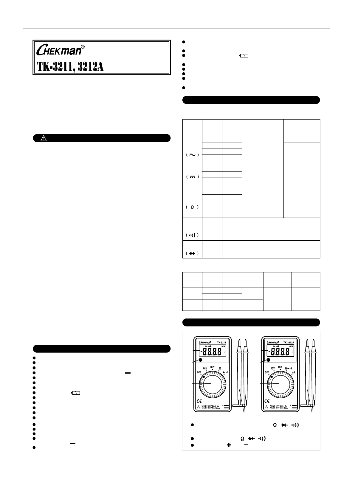
사 양 - SPECIFICATIONS
각부명칭 - DESCRIPTION OF PANEL
◆ 전류(AC/DC mA) TK-3212A only
측정범위 - MEASUREMENT RANGES
+ -
Measuring method : Dual-slope A/D converter
Display : 3½ digit. 1999 count
Range : Auto ranging.
Polarity : Automatic no indication for positive polarity,
minus" "sign for negative polarity.
Over-range indication : " " make indication(Except ACV/DCV ranges)OL
Auto power off : The meter is powered off 15 minute later after
operation was mode.
Sampling : Reading 3times/second
Low battery indication : " " mark is display when the battery
voltage drops below operating voltage.
Power supply : DC3V(CR2032×1)
Operation temperature : 0~40℃, 80%RH(max.)
Storage temperature : -20℃~60℃, 70%RH(max.)
Size & Weight : 55(W) × 109(H) × 11.4(D)㎜, Approx.
100g (included batteries)
Accessories : Instruction manual
+ -
Function Range Resolution Accuracy Input
Resistance
ACV
1.999V
19.99V
199.9V
500V
199.9mV
1.999V
19.99V
500V
199.9Ω
1.999kΩ
19.99kΩ
199.9kΩ
1.999MΩ
1mV
10mV
100mV
1V
100mV
1mV
10mV
1V
100mΩ
1Ω
10Ω
100Ω
1kΩ
±2.3% rdg±3dgt
Approx.11MΩ
Approx.10MΩ
DCV ±1.3% rdg±2dgt
Approx.11MΩ
Approx.10MΩ
OHM ±2% rdg±3dgt
19.99MΩ 10kΩ ±5% rdg±3dgt
Continuity
Checking
199.9Ω 100mΩ
25Ω 이하 경고음
입력단 전압 : 0.4V
Input protection : 250Vrms
Testing Diode
0-1.5V 1mV Open Voltage : approx. 2.2V
Input protection : 250Vrms
기능 범위 정확도 입력저항
교류전압
직류전압
저항
도통시험
다이오드 테스트
분해능
Function Range Resolution Accuracy Input
Resistance Remark
AC mA 19.99mA
199.9mA
19.99mA
199.9mA
10㎂
100㎂
10㎂
100㎂
±2.5%
rdg±3dgt Approx.1Ω
AC/DC
200mA이상
경보음
DC mA ±1.5%
rdg±3dgt
기능 범위 정확도 입력저항 참고
분해능
INSTRUCTION
MANUAL
Function Switch(기능스위치) : ACV /DCV / / / / mA를
선택하는 스위치
Shift Switch(전환스위치) : / / / AC/DC mA 선택 모드
테스트리드 : 적색( ), 흑색( ) 극성
Display
Test leads
Function
switch
Shift
switch
MK
m
VA
DC
AC
AUTO
Test leads
Display
Function
switch
Shift
switch
MK
m
VA
DC
AC
AUTO
SHIFT SHIFT
앞선 기술로 신뢰받는
태광전자정밀산업사
Reliable Manufacturer
본 사 : 부산광역시 남구 문현동 306-16 판매전시장 : TEL. (051)807-6200, 807-6210
TEL. (051)644-2289, 643-2299 FAX. (051)804-4431
FAX. (051)647-3553
#306-16 Munhyundong, Namgu, Pusan, Korea
TEL. 82-51-644-2289, 643-2299 Fax. 82-51-647-3553
Http://www.chekman.com e-mail:chekman@chekman.com
최대입력 전압이상 측정하지 마십시오.
기능스위치를 바꿀 때는 반드시 리드를 회로에서 분리된 상태에서 변경하십시오.
측정하실 때는 리드 안전손잡이 뒷부분을 잡고 측정하십시오.
1. 기능 스위치를 또는 로 선택한다.
2. 화면의 왼쪽에 또는 가 표시된다.
3. 리드를 측정할 회로에 연결한다.
4. 화면에 표시된 값을 읽는다.
ACV DCV
AC DC
Never apply an input signal exceeding the maximum rating input value.
Be sure to disconnect the test pins from the circuit when changing
the function.
Always keep your fingers behind the finger guards on the probe when
making measurements.
1. Set the function switch to or .
2. " " or " " mark will be indicated on the left side in the
LCD display.
3. Connect the leads to the circuit.
4. Read the value on the display.
ACV DCV
AC DC
1. 기능스위치를 " "으로 선택한다.
2. Shift스위치를 눌러 " "를 선택한다.
3. 측정할 회로의 전원을 끈다.
4. 화면의 오른쪽에 " "이 표시된다.
5. 측정할 회로에 연결한다.
6. 화면에 표시된 값을 읽는다.
/ /
1. Set the function switch to " " .
2. Press the to select " "
3. Make sure all power is OFF in the circuit to be measured.
4. " " mark will be indicated on the right side in the
LCD display.
5. Connect the leads to the circuit.
6. Read the value on the display.
/ /
Shift Switch
1. 기능스위치를 " "으로 선택한다.
2. 스위치를 눌러 " "를 선택한다.
3. 화면의 상단에 " "가 표시된다.
4. 측정할 회로의 전원을 끈다.
5. 리드를 측정할 회로에 연결한다.
6. 25Ω이하일때만 부저가 울린다.
/ /
Shift
1. Set the function switch to " "
2. Press the Shift Switch to Select " "
3. " " mark is indicated on the top in the display window.
4. Make sure all power is OFF in the circuit to be measured.
5. Connect the test leads to the circuit to be measured.
6. The buzzer sound when the resistance in a circuit to measure
is less than about 25Ω.
/ /
1. 기능스위치를 " "으로 선택한다.
2. 스위치를 눌러 " "를 선택한다.
3. 화면의 상단에 " "가 표시된다.
4. 다이오드의 음극에서는 흑색리드를 연결하고, 양극에는 적색리드를 연결한다.
5. 정상적인 다이오드는 0.4~0.7V가 표시되고, 역방향에서는 " OL "이 표시
되며, 불량의 개방상태이면 " OL "이표시, 단락상태이면 " O "에 가까운
수치가 표시된다.
/ /
Shift
◈ Testing Diode
1. Set the function switch to " "/ /
2. " "Press the Shift Switch to Select
Never use meter if the meter or test leads are damaged or broken.
Make sure that the test lead are not cut otherwise damaged.
◈ Start-up Inspection
◈ 전압(AC/DCV)측정
◈ Voltage(AC/DCV) Measurement
◈ 저항( )측정
◈ Resistance Measurement
◈ 도통( )시험
◈ Checking Continuity
◈ 다이오드( ) 테스트
기능스위치가 mA로 선택되어 있으면 입력단자로 전압을 측정하지 마십시오.
최대입력 전류 이상은 측정하지 마십시오.
1. 기능스위치를 " "으로 선택한다.mA
2. 스위치를 눌러 " / "를 선택한다.AC DC
Shift
◈ 전류(AC/DC mA)측정 (TK-3212A 만 해당)
4. 리드를 측정할 회로나 부하에 직렬로 연결하여 측정한다.
5. 화면에 표시된 값을 읽는다.
※ 본기기는 199.9mA이하 측정이 가능하고, 이상일때는 " OL "이 표시 되며
측정할 수 없다.
Never apply voltage to the input terminals.
Do not measure more than the maximum input current.
1. Set the function switch to " ".mA
2. " / "AC DC
Press the Shift Switch to select
3. " " mark is indicated on the right side in the LCD display.mA
4. Connect the leads to the circuit.
5. Read the value on the display.
※ The unit can be measured under the 199.9mA and excess value is
displayed "OL" and you can not measured.
1. 본체 후면하단의 나사1개를 풀고 케이스를 여십시오.
2. 끊어진 휴즈를 인두기로 제거한다.
3. 정격에 맞는 휴즈(250V/500mA)를 끼워서 인두기로 납땜한다.
1. Remove the rear case screw with a screwdriver.
2. Remove the breaking fuse.
3. Insert the fuse(250V/500mA) and solder.
1. 건전지가 다 소모되었거나 작동전압 이하로 떨어질 때는 " " 표시가
나타난다.
2. 건전지를 교환하기 전에, 리드를 측정하고 있는 회로에서 분리하여 기능
스위치를 OFF로 선택한다.
3. 본체의 뒷면에 있는 볼트를 풀어 후면을 분리한 후 극성에 맞게DC3V
(CR2032×1)건전지로 교환한다.
1. When the batteries becomes exhausted or drops below the
operating voltage the " " mark is displayed.
2. Turn the function switch OFF and remove the test leads from all
test circuit, prior to installing fresh batteries.
3. Remove the screw of rear case with a screwdriver, change the
DC3V(CR2032×1) into the battery case making sure that proper
polarity is observed.
본 제품은 허용된 입력에는 보호회로가 작동되므로 잔 고장이 생기지 않으나
혹시 고장이나면 가까운 대리점이나 본사로 연락하시면 즉시 조치하겠습니다.
본 제품의 수리를 의뢰하시기 전에 다음의 사항을 점검하시기 바랍니다.
1. 건전지가 다 소모되었는가?
2. 리드의 손상은 없는가?
When make requests for services, please bring the multimeter directly
to the dealer. If this is impossible, however, send the multimeter
directly to our sales office.
If the multimeter fails use, check the following items before sanding
it for repair.
1. Is the battery not exhausted?
2. Are the test lead not disconnected?
◈ Current Measurement(AC/DC mA) ( Only TK-3212A )
◈ 휴즈 교환
◈ Fuse Replacement
◈ 건전지 교환
◈ Replacement of Battery
◈ 유지 및 관리
◈ Maintenance & Repair
+ -
+ -
5. A normal diode will indicated 0.4~0.7V, and the reverse voltage will
indicate " "(same as an open condition), for a short-circuited diode,OL
a value near " " will be displayed.O
측정방법 - MEASUREMENT PROCEDURE
본체나 리드가 파손된 상태에서는 사용을 금합니다.
테스트 리드가 절단되었거나 손상이 없는지 확실히 검사하십시오.
◈ 측정 전 주의사항
3. " " mark is indicated on the top in the display window.
4. Connected the black test pin to the cathode of diode and red
test pin to the anode.
3. 화면의 오른쪽에 " "가 표시된다.mA
This manual suits for next models
3
Other Chekman Multimeter manuals

Popular Multimeter manuals by other brands

socomec
socomec DIRIS A40 instruction manual

Extech Instruments
Extech Instruments 407735 instruction manual

Tenmars
Tenmars TM-87 user manual

Agilent Technologies
Agilent Technologies U1273A quick start guide

LOVATO ELECTRIC
LOVATO ELECTRIC DMK21-22-51-52 quick start guide

Klein Tools
Klein Tools ET100 instruction manual


