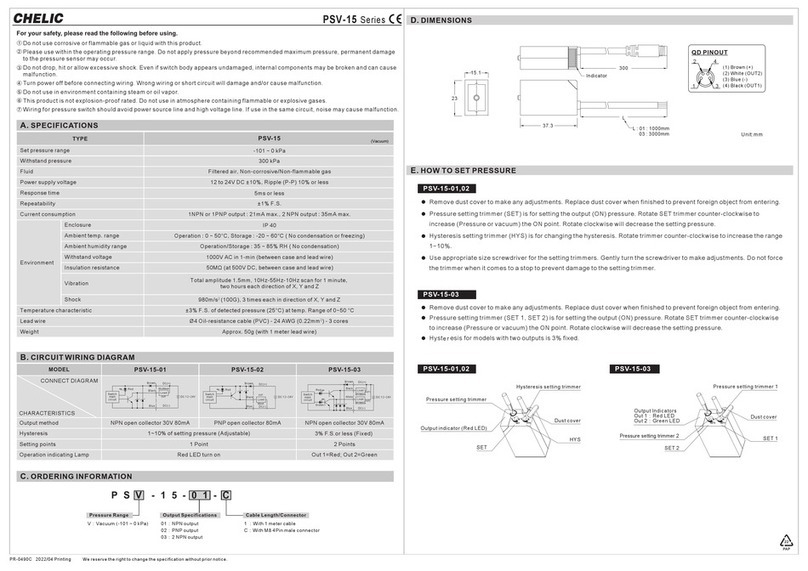
CHELIC PSN 40 Series User manual

Display
12 to 24V DC ±10%, Ripple (P-P) 10% or less
Hysteresis
Environment
Set pressure
resolution
-100.0 ~ 100.0 kPa 0.0 ~ -101.3 kPa
-0.100 ~ 1.000 MPa 10.0 ~ -101.3 kPa
0.000 ~ 1.000 MPa
0.1
0.001
0.001
-
0.01
-
0.001
0.01
0.01
0.1
-
-
-
1
0.1
0.1
-100.0 ~ 100.0 kPa
IP 40
kPa
MPa
kgf/cm2
bar
psi
mmHg
inHg
mmH2O
300 kPa1.5 MPa
PSC-40 (Compound)PSV-40 (vacuum)
PSN-40 (Positive)
PT:1/8”(Rc1/8”),NPT:1/8”,G:1/8"(BSPP)
SPECIFICATIONS
Rated pressure range
Set pressure range
Withstand pressure
Fluid Filtered air, Non-corrosive/Non-flammable gases
Power supply voltage
Current consumption
Switch output
Repeatability(Switch output)
Hysteresis mode
Window comparator mode
Response time
Output short circuit protection
Indicator accuracy
Indicator
Analog output
*(Only type 01, 03)
Ambient temp. range
Ambient humidity range
Withstand voltage
Enclosure
Insulation resistance
Vibration
Shock
Temperature characteristic
Port size
Lead wire
Weight
For your safety, please read the following before using.
Do not use corrosive or flammable gas or liquid with this product.
Please use within the operating pressure range. Do not apply pressure beyond
recommended maximum pressure, permanent damage to the pressure sensor may
occur.
Do not drop, hit or allow excessive shock. Even if switch body appears undamaged,
internal components may be broken and can cause malfunction.
Turn power off before connecting wiring. Wrong wiring or short circuit will damage
and/or cause malfunction.
Do not use in environment containing steam or oil vapor.
This product is not explosion-proof rated. Do not use in atmosphere containing
flammable or explosive gases.
Wiring for pressure sensor should avoid power source line and high voltage line. If
use in the same circuit, noise may cause malfunction.
1
2
3
4
5
6
7
ORDERING INFORMATION
≦55mA
±0.2% F.S. ±1digit
Fixed (3 digits)
≦2.5ms (chattering-proof function: 24ms, 192ms and 768ms selections)
Yes
3 ½ digital, 7 segment LED display ( Red ) (Sampling rate: 5 times/sec.)
±2% F.S. ±1 digit (ambient temperature: 25 ±3°C)
Green Indicator 1 : OUT1 & Red Indicator 2 : OUT2
Operation/Storage: 35 ~ 85% RH (No condensation)
1000V AC in 1-min (between case and lead wire)
50MΩ(at 500V DC, between case and lead wire)
980m/s2 (100G),3 times each in direction of X、Y and Z
±2% F.S. of detected pressure (25°C) at temp. Range of 0~50°C
Ø4 Oil-resistance cable ( PVC ) - 26 AWG ( 0.15 mm² ) - 5 cores
Operation: 0 ~ 50°C, Storage: -20 ~ 60°C (No condensation or freezing)
Approx. 105g (with 2 meter lead wire), Approx. 71g (with M8, 4Pin male connector )
Total amplitude 1.5mm, 10Hz-55Hz-10Hz scan for 1 minute,
two hours each direction of X、Yand Z
Adjustable
Output voltage:
1 to 5V ±2.5% F.S.
(within rated pressure range)
Linearity: ±1% F.S.
NPN: open collector 2 outputs
Max. load current: 80mA
Max. supply voltage: 30V DC
Residual voltage: ≦1V
PNP: open collector 2 outputs
Max. load current: 80mA
Max. supply voltage: 24V DC
Residual voltage: ≦1V
OUTPUT CIRCUIT WIRING DIAGRAMS
PANEL DESCRIPTION
3 ½ digit LED display
Switch (OUT1)
(Green LED)
Display the measured pressure value,
each setting mode and error code.
( ) Button
Switch (OUT 2)
(Red LED)
Use the button to change
setting mode and pre-set
desired value.
Setting Button
Change setting mode and
pre-set final desired value.
Use the button to change
setting mode and pre-set
desired value.
This product has two inlet pressure ports, select
the one most convenient for installation.
Please plug the unused inlet port with supplied
port plug. Use seal tape to prevent pressure leak.
Bolt (screw)
INSTALLATION
1.
2.
Unit:mm
DIMENSIONS
M8 Female connector
TYPE OF SPARE PARTS / DIMENSION GRAPH
Panel mount- FC
Optional Parts
31
42
QD PINOUT
(1) Brown (+)
(2) White (OUT2)
(3) Blue (–)
(4) Black (OUT1)
Output voltage:
1 to 5V ±5% F.S.
(within rated pressure range)
Linearity: ±1% F.S.
( ) Button
PR-0263D 2022/04 Printing We reserve the right to change the specification without prior notice.
PS -40
CHELIC PNEUMATIC
PSN(C,V)-40 Series
Output voltage:
1 to 5V ±2.5% F.S.
(within rated pressure range)
Linearity: ±1% F.S.
N : Positive
(-0.100~1.000MPa)
C : Compound
(-100.0~100.0kPa)
V : Vacuum
(10.0~-101.3kPa)
PT : 1/8"(Rc1/8")
NPT : 1/8"
G : 1/8”(BSPP)
Blank : 2 meter cable
QD : M8, 4Pin
male connector
(Only type : 02,04)
01 : 2 NPN output &
1 Analog output
02 : 2 NPN output
03 : 2 PNP output &
1 Analog output
04 : 2 PNP output
PS C - 40 – 01 – NPT – – BT02
Blank : Standard Type
BT01 :
Vertical Mounting Bracket
BT02 :
Horizontal Mounting bracket
FC :
Panel Mounting Adapter+Lid
Pressure Range
Output Specifications
Pressure Port Cable Length/
Connector
PS - 40 - 01
NPN Output & Analog Output
DC(–)(Blue)
OUT2(White)
OUT1(Black)
(Orange)
DC(+)(Brown)
Analog output
DC
12-24V
Main circuit
RL
RL
PS - 40 - 02
NPN Output
DC
12-24V
Main circuit
RL
RL
DC(–)(Blue)
OUT2(White)
OUT1(Black)
DC(+)(Brown)
PS - 40 - 03
PNP Output & Analog Output
DC
12-24V
Main circuit
RL
RL
DC(–)(Blue)
OUT2(White)
OUT1(Black)
(Orange)
DC(+)(Brown)
Analog output
PS - 40 - 04
PNP Output
DC
12-24V
Main circuit
RL
RL
DC(–)(Blue)
OUT2(White)
OUT1(Black)
DC(+)(Brown)
42.4
42.4
7
47.4
40
40
35.5
4.5
Front protective lid
FC-01 Panel adapter
FC-02
36×36±0.3mm
Panel adapter
FC-03
T≦4.5mm
FC-01 Front protective lid
FC-02 Panel adapter
FC-03 Panel adapter
Mounting
bracket
BT01 Vertical Mounting Bracket
BT0 2 Horizontal Mounting bracket
37.1
13
12.9
4.2
20
5.0
6.1
5.0
25
4.2
45.5
26.2
M8*1
2000
32
7
Mounting bracket
BT01
Mounting
bracket
BT02
Unit:mm
300
www.chelic.com
1kΩ
1kΩ

Measure mode
初使設定模式
Response time setting
OUT2 mode setting
初使設定模式
OUT1 mode setting
初使設定模式
Unit setting
Measure mode
Setting zero point under
atmospheric pressure
Output Mode
Unit
Response Time
Auto/Manual
P_1 or n_1
P_2 or n_2
P_3 or n_3
P_4 or n_4
SETTING STEPS
Measure mode
SET
SET
SET
SET
SET
SET
NC ModeNO Mode
2.5ms 24ms 192ms 768ms
Manual setting
mode
Auto setting
mode
Use the or button to set desired pressure unit.
Press(SET) button for more than 3 seconds.
Use the or button to set OUT1 mode.
Use the or button to select response time.
Use the or button to set OUT2 mode.
Use the or button to select auto/manual setting.
mmHg (*1)
psi
inHg (*1)mmH2O (*1)
MPa kgf/cm2bar
Output type:
NO: normal open mode
NC: normal close mode
Output type:
NO: normal open mode
NC: normal close mode
INITIAL SETTING MODE
Pressure value setting
:Auto/Manual
PRESSURE SETTING MODE
Alternately displayed
(*1)
(*1)
(*1)
(*1)
(*2)
(*2)
(*2)
(*2)
Measure mode
Measure mode
The LED shows (P_*) at normal open mode and (n_*) at normal close
mode.
Pressure setting value is shown normally and will not lead to pressure
sensor pause or stop working.
Change pressure value:
Press button, each press will increase one digit.
Keep pressing the button, the pressure value will keep increasing.
Press button, each press will decrease one digit.
Keep pressing the button, the pressure value will keep decreasing.
NOTE :
Select auto/manual setting mode during initial set-up.
*1.
*2.
OUT2
OUT1
Manual setting mode
【Calculation of Setting value】
P
2
(
n2
)
P
4
(
n4
)=
B+
A-B
4
A=The max. pressure value under auto setting mode.
B=The min. pressure value under auto setting mode.
P
1
(
n
1
)
P
3
(
n
3
)=
A –
A-B
4
P
2
(
n
2
)
P
4
(
n
4
)=
B +
OUT2
OUT1 (*1)
(*3)
(*2)
Measure mode
Measure mode
(*3)
Prepare auto setting mode
at OUT1 switch.
Prepare auto setting mode
at OUT2 switch.
NOTE :
*3.
*1.
*2.
In case of without need of OUT1 pressure value setting,
press at the same time to enter (AP2)/(An2).
In case of without need of OUT2 pressure value setting,
press at the same time to enter measure mode.
The LED show「AP*」at normal open mode and 「An*」at
normal close mode.
Under this mode, the device
needs to be set repeatedly
in order to reach the auto
setting value.
Under this mode, the device
needs to be set repeatedly
in order to reach the auto
setting value.
Positive/Compound
(PSN-40/PSC-40)
Hysteresis Mode :
Output hysteresis value can be pre-set.
Normal open mode
Normal open mode
P1(n1)>P2(n2)
P3(n3)>P4(n4)
P_1
P_3
P_2
P_4
Positive Pressure
Positive Pressure
P_1
P_3
P_2
P_4
n_1
n_3
n_2
n_4
P_1
P_3
P_2
P_4
n_1
n_3
n_2
n_4
Vacuum Pressure
Vacuum Pressure
Positive Pressure Vacuum Pressure
Positive Pressure Vacuum Pressure
When hysteresis mode setting is within 2 digits,
if the input and pre-set pressure is quite near,
pressure sensor output might cause chattering.
P_1
P_3
P_2
P_4
n_2
n_4
n_1
n_3
n_2
n_4
n_1
n_3
H=3digits
Vacuum
(PSV-40)
OUTPUT TYPE
Window comparator mode :
Within pressure setting range, pressure sensor
output can be ON or OFF.
P1(n1)<P2(n2)
P3(n3)<P4(n4)
Positive/Compound
(PSN-40/PSC-40)
Normal open mode
Vacuum
(PSV-40)
Positive/Compound
(PSN-40/PSC-40)
Normal open mode
Normal open mode
Vacuum
(PSV-40)
Positive/Compound
(PSN-40/PSC-40)
Normal open mode
Vacuum
(PSV-40)
Hysteresis is fixed in 3 digits.
Pressure value level setting: At least 6 digits.
NOTE : NOTE :
The Min. value display mode:
Press button 2 seconds to enter the min. value mode, pressure sensor
will detect the min. value and keep display.
Press button 2 seconds to return to measure mode.
Press the + button at the same time until the "00" is shown.
Release the button to end zero point setting.
Zero point setting:
The Max. value display mode:
Press button 2 seconds to enter the max. value mode, pressure sensor
will detect the max. value and keep display.
Press button 2 seconds to return to measure mode.
ZERO POINT SETTING /THE MAX. & MIN. DISPLAY MODE
SET
Unlock mode Lock mode
Press (SET ) more than 5seconds.
Use or to select key lock/unlock mode.
Key lock mode can prevent operation mistakes.
KEY LOCK / UNLOCK MODE
Measure mode Measure mode
CHANGE PRESSURE UNIT TAG
When the pressure setting is not kPa or MPa, please remove the pressure unit tag and
place the selected tag on the indicated area of the faceplate to assure the pressure unit
is not misemployed and that setting error does not occur.
When using a unit mmH2O, please multiply display value by 100.
Applied
pressure error
System error
The applied pressure is excess the upper limit of pressure setting.
Adjust the pressure within applied
pressure range.
Internal data error
Turn power off, and then restart. If error
condition remains, please return to
factory for inspection.
---
----
Error Name
Error code
Error instruction Troubleshooting
Excess load
current error
Residual
pressure error
Excess load current of 80 mA
OUT1
OUT2
Turn power off and check the cause of
overload current or lower the current
load under 80 mA, then restart.
Change input pressure to ambient
pressure and perform zero reset again.
The applied pressure is excess the lower limit of pressure setting.
Internal
system
error
Internal data error
Internal
system
error
During zero reset, ambient pressure is over
±3% F.S.
ERROR CODE INSTRUCTION
kPa
kgf/cm
2
mmHg
inHg
bar
psi
MPa
mmH2ONOTE :
SET
SET
SET
SET
SET
SET
SET
SET
SET
SET
NC ModeNO Mode
*1: Only for PSV-40, PSC-40
From To
1 kPa
1 MPa
1 Pa
1000.000
1000000
1
98066.5
133.32
6895 6.895 0.006895 0.07031 51.7157 10.06895 2.036074 703.07
0.2953
295.2998
0.0002953 0.101968
101.9689
101968.9
0.010000
10
0.00001
0.145038
145.038
0.000145038
7.500616
7500.616
0.00750062
0.010197
10.197
0.000010197
0.001000
1
0.000001
1
1000
0.001
100000.0 100.0000 0.100000 1.01972 750.062 14.5038 129.52998
28.95979 10000.200.98066514.2233735.5591
0.0980665
98.0665
3386.388
9.80665
3.386388
0.00980
0.003386
-
0.034530
0.000099
25.40000
0.0735578
0.491141
0.00142
0.033863
0.000098
1
0.002895
345.324
1
0.039370 13.59540.00133320.01933610.00135950.0001330.13332
1 kgf/cm
2
1 mmHg
1 psi
1 bar
1 inHg
1 mmH
2
O
Pa kPa MPa
kgf/cm
2
mmHg psi bar inHg
10196.89
mmH
2
O
ANALOG OUTPUT
Analog Output range 1 to 5V, proportional to the pressure range.
(Compound) (Vacuum) (Positive)
Analog output (V) Analog output (V) Analog output (V)
5
3
1
5
1
5
1
-100.0 0.0 100.0 (kPa) 0.0 -101.3 (kPa) 0.000 1.000 (MPa)
(Low) (High) (Low) (High) (Low) (High)
High Precision Digital Pressure
PS -40
CHELIC PNEUMATIC
Zero point settingPressure settingInitial setting
Measure mode
Alternately displayed
Alternately displayed
Alternately displayed
Auto setting mode
A-B
4
www.chelic.com PAP
22
This manual suits for next models
3
Other CHELIC Switch manuals
Popular Switch manuals by other brands
MDT Technologies
MDT Technologies MDT Glass Push-button II Smart Technical manual

Conrad
Conrad 97 51 23 operating instructions
Cisco
Cisco Catalyst 3000 Regulatory compliance and safety information

ATEN
ATEN Bi-Tronics AF-241 user manual

Avocent
Avocent AutoView 1415 Quick installation guide
Edimax
Edimax ES-5208P Quick installation guide
