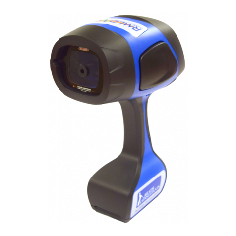
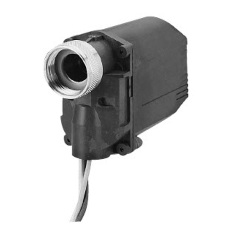
Chentronics iScan3 Series User manual

MNL-ISCAN3, REVB INSTALLATION & OPERATION MANUAL Page 1 of 25
DCO #12743 For Technical Support Call: +1.866.821.5504 Schedule Document
KEEP THIS MANUAL IN A SAFE PLACE FOR FUTURE REFERENCE!
Read this manual before using this product. Failure to follow the instructions and safety precautions in this manual can result in
serious injury or death or damage to equipment.
Applicable Scanner Part Numbers
Contact Technical Support +1.866.821.5504 with any questions.
For a list of relevant patents and trademarks, please see http://www.chentronics.com/legal-notices.
PART NUMBER
MODEL
AREA CLASSIFICATION
TEMP RATING
FEATURE
CONNECTOR PINS
04004999-MB
iS3-MB
CLASS I/DIVISION II
-40°C to 80°C
Fully Programmable –Must Be
Configured Prior to Use
16
04004999-SB
iS3-SB
CLASS I/DIVISION II
-40°C to 80°C
Limited Programmability
16

MNL-ISCAN3, REVB INSTALLATION & OPERATION MANUAL Page 2 of 25
DCO #12743 For Technical Support Call: +1.866.821.5504 Schedule Document
Contents
IMPORTANT SAFETY INFORMATION..................................................................................................................................................3
CUSTOMER SUPPORT ........................................................................................................................................................................5
PRODUCT FEATURES..........................................................................................................................................................................6
EASE OF INSTALLATION ................................................................................................................................................................................6
THERMAL PROTECTION................................................................................................................................................................................8
TECHNICAL SPECIFICATIONS ..............................................................................................................................................................9
DEFINITIONS..............................................................................................................................................................................................9
SPECIFICATION TABLE................................................................................................................................................................................10
Technical Specification NOTES ........................................................................................................................................................11
DEFAULT CONFIGURATION (SETTINGS)..........................................................................................................................................................12
WIRING INSTRUCTIONS ...................................................................................................................................................................13
WIRING DIAGRAM....................................................................................................................................................................................13
Wiring Notes ...................................................................................................................................................................................13
CABLE CONNECTION..................................................................................................................................................................................16
POWER/CONTROL CABLE INSTALLATION .......................................................................................................................................................16
LOCKING NUT INSTALLATION ......................................................................................................................................................................16
COMMUNICATIONS WIRING ...........................................................................................................................................................18
RS-485..................................................................................................................................................................................................18
“DAISY CHAIN”CONFIGURATION.................................................................................................................................................................19
SPLIT OR “Y” CONFIGURATION....................................................................................................................................................................20
REMOTE FILE SELECT.................................................................................................................................................................................21
SIGHTING THE SCANNER..................................................................................................................................................................22
FLAME LINE OF SIGHT................................................................................................................................................................................22
RING OF LIGHT SCANNER STATUS DISPLAY.....................................................................................................................................................23
MAINTENANCE................................................................................................................................................................................24
CLEANING THE LENS..................................................................................................................................................................................24
SPECIAL,“X”, CONDITIONS OF USE..............................................................................................................................................................25

MNL-ISCAN3, REVB INSTALLATION & OPERATION MANUAL Page 3 of 25
DCO #12743 For Technical Support Call: +1.866.821.5504 Schedule Document
IMPORTANT SAFETY INFORMATION
Read All Instructions before Using Equipment
The instructions provided in this manual have been prepared to serve as a general guide. It is intended for use by
qualified personnel with knowledge of equipment of this type. It is not intended to cover all possible variations in
equipment or to provide for specific operating problems which may arise.
You are responsible for adhering to all warnings or cautions provided in this Manual.
In addition to any general safety measures provided in this Manual, you must comply with all current national, state,
local and company safety regulations at all times.
Safety Symbols used in this manual comply with ISO 3864.
THESE SYMBOLS ARE USED TO ALERT YOU TO POTENTIAL PERSONAL INJURY HAZARDS.
OBEY ALL SAFETY MESSAGES THAT FOLLOW THESE SYMBOLS TO AVOID POSSIBLE INJURY OR DEATH.
Indicates a hazard with a high level of risk which, if not avoided will result in death or
serious injury.
Indicates a hazard with a medium level of risk which, if not avoided could result in
death or serious injury.
Indicates a hazard with a low level of risk which, if not avoided will result in minor or
moderate injury.

MNL-ISCAN3, REVB INSTALLATION & OPERATION MANUAL Page 4 of 25
DCO #12743 For Technical Support Call: +1.866.821.5504 Schedule Document
EXPLOSION HAZARD
Do not open the equipment cover or service the equipment if an explosive atmosphere may be present.
Equipment must be installed and serviced by qualified personnel in accordance with applicable local and
national codes, standards, and ordinances.
Lisez toutes les instructions avant d'utiliser l'équipement
Les instructions fournies dans ce manuel ont été préparées pour servir de guide général. Il est destiné à être utilisé par
du personnel qualifié connaissant l'équipement de ce type. Il n’est pas destiné à couvrir toutes les variations possibles
d’équipement ni à régler les problèmes de fonctionnement spécifiques qui peuvent survenir.
Vous êtes responsable du respect de tous les avertissements ou mises en garde fournis dans ce manuel.
En plus des mesures de sécurité générales fournies dans ce manuel, vous devez respecter à tout moment toutes les
réglementations de sécurité nationales, nationales, locales et de l'entreprise.
Les symboles de sécurité utilisés dans ce manuel sont conformes à la norme ISO 3864.
CES SYMBOLES SONT UTILISÉS POUR VOUS AVERTIR DES RISQUES DE BLESSURES POTENTIELS.
RESPECTEZ TOUS LES MESSAGES DE SÉCURITÉ QUI SUIVENT CES SYMBOLES POUR ÉVITER LES BLESSURES POTENTIELLES OU LA MORT.
Indique un danger avec un niveau élevé de risque qui, s’il n'est pas évité, entraînera la
mort ou des blessures graves.
Indique un danger avec un niveau de risque moyen qui, s’il n'est pas évité, pourrait
entraîner la mort ou des blessures graves.
Indique un danger avec un niveau de risque bas qui, s’il n'est pas évité, entraînera des
blessures mineures ou modérées.

MNL-ISCAN3, REVB INSTALLATION & OPERATION MANUAL Page 5 of 25
DCO #12743 For Technical Support Call: +1.866.821.5504 Schedule Document
TENSION DANGEREUSE
N'ouvrez pas le capot de l'équipement et ne le réparez pas si une atmosphère explosive peut être
présente. L'équipement doit être installé et entretenu par du personnel qualifié conformément aux codes,
normes et ordonnances locales et nationales applicables
Customer Support
For Technical Support
Inside USA Call: 866.821.5504
Outside USA Call: +1.607.334.5531
Website: www.chentronics.com

MNL-ISCAN3, REVB INSTALLATION & OPERATION MANUAL Page 6 of 25
DCO #12743 For Technical Support Call: +1.866.821.5504 Schedule Document
Product Features
The iScan3 flame scanner is designed to detect flame from fossil fuels such as natural gas, refinery gas, waste gas, fuel oils,
biomass and coals. The iScan3 consists of an integrated viewing head and signal processor. No secondary signal processor or
amplifier is required.
Ease of Installation
QUICK-CONNECT BURNER MOUNT:
The simple cam-and-groove mechanism allows for quick mounting, release, and rotation of the scanner.
QUICK CONNECT I/O CABLE:
The iScan3 input connector allows quick disconnect even in hazardous areas

MNL-ISCAN3, REVB INSTALLATION & OPERATION MANUAL Page 7 of 25
DCO #12743 For Technical Support Call: +1.866.821.5504 Schedule Document
LED STATUS INDICATORS; “Ring of Light”:
The iScan3 is equipped with a highly visible LED status indicator ring. This “Ring of Light” communicates the scanner’s
operating modes including FLAME SIGNAL STRENGTH, GAIN LEVEL (the amount of signal amplification), and
WARNINGS/FAULTS. This ring aids with “sighting”the flame; or in other words: proper aiming of the scanner. This
must be done with care to ensure that a good flame signal is present over a range of operating conditions. With the
“Ring of Light”, the operator can quickly recognize marginal conditions (such as low flame strength and/or high gain).
REMOTE FILE SELECT
The Remote File Select feature provides a means for selecting one
[A1]
of the configuration files resident within the
scanner. Single-Burner, “SB”, models have limited programmability while Multi-Burner, “MB”, models have a high
degree of programmability, as outlined in the table below.
SCANNER
PART NUMBER
USER PROGRAMMABLE FEATURES (with iScan Software)
4-20 mA
SIGNAL
MAPPING
4-20 mA
Calibrate
4-20 mA
Gain
SECONDARY
RELAY:
Redundant
Flame N.O. or
N.C. -or-
Fault N.O. or N.C.
DETECTION
SETTINGS:
Gain, Freq,
Threshold
MULTIPLE
SETUP
FILES
(max of 4)
RESPONSE TIMES
(FLAME ON/
FLAME OFF)
04004999-SB
YES
YES
YES
YES
NO
NO
NO
04004999-MB
YES
YES
YES
YES
YES
YES
YES

MNL-ISCAN3, REVB INSTALLATION & OPERATION MANUAL Page 8 of 25
DCO #12743 For Technical Support Call: +1.866.821.5504 Schedule Document
Thermal Protection
The iScan3 Flame Scanner has redundant safety features for exposure above the maximum temperature rating. The modes of
operation are described below:
Mode
Internal Temperature (TINT)
4-20 Output Setting
Indicator Light Setting
Relay Operation
Normal
TINT ≤ 95°C
Normal (4-20 mA)
Normal
Normal
Warning
95°C < TINT < 100°C
3mA steady
Alternate left half yellow 0.5s
/ right half yellow 0.5s
Normal
Fault
100°C < TINT ≤ 105°C
2mA steady
Blink yellow 0.5s on 0.5s off
Relays Open and will not
Close
Disable
TINT > 105°C
1mA steady
Yellow Solid
Relays Permanently Open
and will not Close

MNL-ISCAN3, REVB INSTALLATION & OPERATION MANUAL Page 9 of 25
DCO #12743 For Technical Support Call: +1.866.821.5504 Schedule Document
Technical Specifications
Definitions
FLICKER –Flicker or Flicker Frequency refers to the modulation of flame intensity due to micro-explosions.
FDORT –Flame Detector ON Response Time –the period of time from flame intensity rising above the user adjustable
threshold to flame relay contacts closed.
FDRT –Flame Detector Response Time –the period of time between the loss of a sensed flame and the signal
indicating the absence of flame.
MFFRT –Marginal Flame Fail Response Time –period of time from flame intensity falling below the the user
adjustable threshold to the flame relay contacts open.
ROL –Ring of Light –multi-colored LED status indication on the back of the scanner.
iScan Software –Flame Scanner Communications software used to monitor and configure the iScan3 device.
GAIN –When a signal is amplified, GAIN is the ratio of the amplified signal relative to the original.
DISCRIMINATION –The ability to distinguish between multiple flames. An example of good discrimination is when
the MB scanner is able to recognize a pilot flame with other burner’s main fuel flame in the background. The status of
the background Flames
[A2]
does not affect the ability to detect the pilot flame (ON or OFF).

MNL-ISCAN3, REVB INSTALLATION & OPERATION MANUAL Page 10 of 25
DCO #12743 For Technical Support Call: +1.866.821.5504 Schedule Document
Specification Table
AREA CLASSIFICATION
Hazardous/Non-Hazardous Area
Part Number
PN 04004999-SB, 04004999-MB
Area Classification
Input Cable
Quick Disconnect - Separate Cable
Weight
2.25 lb. (1.02 kg)
Mounting
1” NPT(F)
Purge Air NOTE 1
Flow
Pressure
5 scfm (8.5 Nm3/hr)
5” w.c. (13 mbar)
ROL - Ring of Light Status
Indicator
Color Coded Status
Field of View
6 Degrees
Optics
Quartz Lens
Sensor Type
Solid-State
Sensor Range
300 nm 750 nm
Communication
USB/RS485: up to 127 up to a distance of 4000 Ft. (1200 M).
Temperature
-40°C to 80°C
Humidity
0 to 100% Relative Humidity, Condensing
Input Power NOTE 2
24 VDC, +10%/-15%, 5.28 W (220 mA)
Relay Contacts NOTE 3
Primary Relay with Normally Open and Normally Closed Voltage Free Contacts (i.e.
NO contact closes when flame is detected, NC opens when flame is detected)
Secondary Relay with Voltage Free Contacts
(configurable as NO Flame Relay or Fault Relay configurable as NO or NC contacts)
0.125A @ 250 VAC Resistive Load
0.250A @ 125 VAC Resistive Load
1.0 A @ 24 VDC Resistive Load
Signal Output NOTES 4,5
Output #1, 4–20 mA, Flame Signal
Output # 2, 4-20 mA, Selectable as Gain or Internal Temperature
Maximum Current Loop Resistance = 750 ohms
FDORT (FLAME ON)
Configurable from 1-4 seconds in 1 second increments
FDRT (FLAME OFF)
Configurable from 1-4 seconds in 1 second increments
MFRRT
Configurable from 1-6 seconds in 1 second increments

MNL-ISCAN3, REVB INSTALLATION & OPERATION MANUAL Page 11 of 25
DCO #12743 For Technical Support Call: +1.866.821.5504 Schedule Document
AREA CLASSIFICATION
Hazardous/Non-Hazardous Area
Part Number
PN 04004999-SB, 04004999-MB
Safety Integrity Level (SIL3)
Data
PFDavg = 938.369 X 10⁻⁶
λS = 1.14 X 10⁻⁶
λDD = 2.1705 X 10⁻⁶
λDU = 0.0219 X 10⁻⁶
SFF = 99.1%
Proof Test Interval
time = 1 year (8760 Hrs) NOTE 6
Technical Specification NOTES
Note 1 Purge air pressure is the minimum differential pressure required between the purge air supply pressure at “Y”
(scanner connection) and the back pressure.
Note 2 24 VDC Power supply to iScan3 must not include any inductive load.
Note 3 To achieve higher relay contact voltages, use iScan3 relay contacts to energize the coil of an interstitial relay.
Note 4 Output for monitoring only. Not to be used to prove flame.
Note 5 4-20 mA outputs are calibrated at the factory to a known load. Monitoring hardware will have an impact of the
current output. For accurate readings, 4-20 mA output(s) should be calibrated using a milli-ammeter between the
scanner’s 4-20 mA output and the monitoring hardware. Refer to the 4-20 ma Settings section MNL- iScan
Software for details on how to execute the calibration procedure.
Note 6
SUGGESTED SIL3 PROOF TESTS:
An annual proof test is good practice to meet the requirements in terms of IEC61508. According to section
7.4.3.2.2 f of IEC61508 proof tests shall be undertaken to reveal dangerous faults which may be undetected
by diagnostics test.
Flame OFF: Shutdown the burner and ensure that the flame off condition is detected and signaled by the
flame detector as a flame off condition.
False Flame: Verify that prior to start up (no flame present) there is no indication of a flame on condition
(false flame signal) on the flame scanner (this is typically integrated within the BMS as a pre-start permissive
to prevent start up if a false flame condition is detected. This should not be considered a replacement for
recommended testing of the scanner adjustments which are required to be verified each time the scanner is
commissioned, adjusted, settings are changed or re-commissioning takes place. In these cases, only qualified
personnel who have been trained and are experienced should make such adjustments.

MNL-ISCAN3, REVB INSTALLATION & OPERATION MANUAL Page 12 of 25
DCO #12743 For Technical Support Call: +1.866.821.5504 Schedule Document
Default Configuration (Settings)
As part of setup in iScanSoftware, each scanner is assigned unique addresses.
Flame Detector On Response Time (FDORT)
2 seconds nominal
Flame Detector Response Time (FDRT)
1 second nominal
Marginal Flame Failure Response Time (MFFRT)
2 seconds nominal
Gain Configuration
Manual
Gain Channel
High
Signal Gain
3.5
Flame Flicker Frequency
26 Hz
Flame Flicker Bandwidth
12 Hz
Flame Flicker Threshold
-45 dB
Mains Filter
Enabled
Rail Filter
Enabled
Solar Filter
Enabled
Flame Filter
Enabled
The following settings apply to the overall scanner and not to an individual scanner file:
Communications Address
COMM 1NOTE 1
Active File
A
Remote File Select
Disabled
Multiple Fuels
Disabled
4 To 20 mA Gain
1 mA/dB above
threshold

MNL-ISCAN3, REVB INSTALLATION & OPERATION MANUAL Page 13 of 25
DCO #12743 For Technical Support Call: +1.866.821.5504 Schedule Document
Wiring Instructions
All wiring shall be done in accordance with all applicable local and national codes, standards, and ordinances. The
scanner has a quick connect cable. This cable does not require a flexible conduit if permitted by local authority.
Connections for power, Earth Ground, and Flame Relay (N.O. and Common) are required for all applications. Use of
the 4-20 mA outputs, Communications, and connections are “as-required” for each application.
Wiring Diagram
Wiring Notes
Note 1 If more than one 24 VDC supply is required, the 24 VDC returns labeled as “DC (-)” shall be connected to each
other.
Note 2 If more than one 24 VDC supply is required, the 24 VDC source connections labeled as “DC (+)” shall be
isolated from all other power supplies. If switching power supplies are used the supplies may be connected via a
wired OR diode configuration. NOTE: the BLOCKING DIODE must be rated for a minimum of 50 volts and 10 Amps.
Note 3 The 24 VDC return, “DC (-)”, shall be used as the low side of the File Select relays.
Note 4 The 24 VDC return, “DC (-)”, is the return for the 4–20 mA output loop(s). Input must be isolated type.
Maximum current loop resistance is 750 ohms.

MNL-ISCAN3, REVB INSTALLATION & OPERATION MANUAL Page 14 of 25
DCO #12743 For Technical Support Call: +1.866.821.5504 Schedule Document
Note 5 Connect the scanner Earth GND (Green/Yellow, 8, <H>) to EARTH GROUND. A short BRAIDED CONDUCTOR
(alternately a short AWG #12 wire) is recommended.
Note 6 All shields are tied to Earth Ground in the Control Panel only.
Electrical noise interference from high voltage/energy ignition sources can adversely affect the operation
of the flame scanner. To minimize the possibility of electrical noise interfering with the operation of the
flame scanner:
•Do not install ignition wires in the same conduit as the scanner wires.
•Ignition Systems shall have a dedicated return.
•Do not mount an ignition transformer in the same enclosure where the flame scanner wiring is
terminated.
•Ignition cables shall be routed a minimum of 12” (305mm) from scanner wiring at all times.
•iScan3 complies with IEC 61000-4-3 (RF Radiated Immunity).
Earth GND
GREEN/YELLOW (8) <H> CONNECT TO EARTH
GROUND. (See section on grounding methods)
CONNECT ALL SHIELDS AT ONE END ONLY TO EARTH GROUND.
DO NOT GROUND SHIELDS AT THE LOCAL JUNCTION BOX.
Earth Ground
Located at CONTROL PANEL
ALL OTHER CONNECTIONS

MNL-ISCAN3, REVB INSTALLATION & OPERATION MANUAL Page 15 of 25
DCO #12743 For Technical Support Call: +1.866.821.5504 Schedule Document
•Les interférences électriques provenant de sources d'allumage haute tension / énergie
peuvent nuire au bon fonctionnement du scanner à flamme. Pour minimiser les risques
d'interférences électriques avec le fonctionnement du scanner à flamme:
•Ne pas installer les câbles d'allumage dans le même conduit que les câbles du scanner
•Les systèmes d'allumage doivent avoir un retour dédié
•Ne montez pas de transformateur d'allumage dans le même boîtier que le câblage du scanner
à flamme
•Les câbles d’allumage doivent être acheminés à au moins 12 pouces (305 mm) du câblage du
scanner en tout temps.
•iScan3 est conforme à la norme IEC 61000-4-3 (Immunité par rayonnement RF).

MNL-ISCAN3, REVB INSTALLATION & OPERATION MANUAL Page 16 of 25
DCO #12743 For Technical Support Call: +1.866.821.5504 Schedule Document
Cable Connection
Power/Control Cable Installation
The iScan3 system utilizes a quick disconnect connector to connect the power/control cable to the electronics.
To connect the power cable to the electronics, first turn the locking nut clockwise by hand until it is seated against the
electronics. This will ensure the locking nut is not too far out and will allow the connector to properly seat. Then, align the
connector on the cable with the connector on the electronics, insert the connector, and turn the outer barrel clockwise until
the banjo fittings on the connector are seated and latched.
FIGURE A:CLEAR THE LOCKING NUT THEN ALIGN AND INSERT THE CABLE CONNECTOR.
Locking Nut Installation
The equipment features a locking nut that locks the cable to the equipment so that it may not be removed without the use of
a tool. This feature is required for some hazardous area installations. To lock the connector in place, turn the locking nut
counter-clockwise tighten to a torque of 10ftlbs using a wrench. See Figure B and Figure C for illustration of locking nut
tightening.To remove the cable, turn the locking nut clockwise until it is seated against the electronics, then remove the cable
connector by turning the outer barrel counter clockwise until the banjo fittings unseat and the connector unseatS
[A3]
and can
be removed.
Scanner

MNL-ISCAN3, REVB INSTALLATION & OPERATION MANUAL Page 17 of 25
DCO #12743 For Technical Support Call: +1.866.821.5504 Schedule Document
FIGURE B: SEAT THE CONNECTOR AND SEAT THE LOCKNUT AGAINST THE CONNECTOR BARREL.
FIGURE C: TIGHTEN LOCKING NUT AGAINST CONNECTOR BARREL.
EXPLOSION HAZARD
DO NOT CONNECT OR DISCONNECT WHEN ENERGIZED
TENSION DANGEREUSE
NE PAS CONNECTER OU DÉBRANCHER LORSQUE ÉNERGÉ

MNL-ISCAN3, REVB INSTALLATION & OPERATION MANUAL Page 18 of 25
DCO #12743 For Technical Support Call: +1.866.821.5504 Schedule Document
Communications Wiring
RS-485
Communication with the iScan3 is RS-485 via a USB to RS-485 Converter (PN 3425-057-01). RS-485 is a differential multi-drop
network. For iScan3, the network is a half-duplex, 2-wire, echo-off configuration operating at 19200 KBAUD. The maximum
allowable number of nodes on a given section of the network is 32 including the USB to RS-485 converter and any repeaters. If
more than 32 loads are connected (1 USB converter, 1 RS-485 repeater and 30 iScan3s) then an RS-485 repeater is required
between sections to boost the signal. The repeater must be compatible with the EIA-485 standard, must have input to output
DC isolation, must operate on 24VDC over the operating temperature range of -30°C to +70°C and must have agency
approvals sufficient to meet the area classification.
NOTE: When calculating 32 loads, include the USB to RS-485 converter and the number of repeaters in a section).
For the extended sections, up to 30 iScan3s may be connected. The maximum length of any given section is 4000 FT
(1200 M).
B&B Electronics 485 repeater model 485OPDRI-PH meets these requirements. Additional repeaters may be added to extend
the network to 127 scanners. If
[A4]
using the B&B Electronics 485 repeater model mentioned above, configure the DIP
switches on ports as follows:
1
2
3
4
5
6
7
8
ON
ON
ON
ON
OFF
OFF
ON
OFF
Since there is no dedicated signal reference, the 24 VDC return labeled as DC (-) is used. The USB to RS-485 and the Repeaters
must have their GND terminals connected to the DC (-) as well. Failure to provide the signal reference may result in
communication errors and potentially damage the iScan3.
The recommended topology is “Daisy Chain” as shown in the wiring diagrams below. A split or Y configuration is acceptable.
NO OTHER CONFIGURATION IS ACCEPTABLE. Please refer to the EIA-485 specification for further information on RS-485
networks.
COMMUNICATION WIRING SUMMARY:
•Wiring must be twisted pair shielded cable. Ground the shield only at the control panel to prevent ground loops.
•Use only “Daisy Chain” or “Y” configurations. Connect all of the “Com A” wires together. Connect all of the “Com B” wires together. Make sure that the
“Com A” and “Com B” wires are connected to the correct terminals on the converter.
•An RS-485 repeater is required for every 30 scanners or 4000 ft (1200 m) of length for a maximum of 127 scanners in a network.
•Ensure the DC (-) of all scanners are tied together as a reference for RS-485 communications. The GND terminal of the USB to RS-485 converter and the
repeaters must also be connected to the DC (-) of the scanners.

MNL-ISCAN3, REVB INSTALLATION & OPERATION MANUAL Page 19 of 25
DCO #12743 For Technical Support Call: +1.866.821.5504 Schedule Document
“Daisy Chain” Configuration

MNL-ISCAN3, REVB INSTALLATION & OPERATION MANUAL Page 20 of 25
DCO #12743 For Technical Support Call: +1.866.821.5504 Schedule Document
Split or “Y” Configuration
This manual suits for next models
2
Table of contents
