Cheonsei KEMPION AC- 15A Series User manual


Tank you very much for purchasing KEMPION Accessories.
Before beginning operation, please read this instruction manual carefully. Correct
handling, repair, & maintenance are described easily.
Please use these accessories safely to be guaranteed performance & long life of the
accessories after reading this instruction manual.
Please keep this instruction manual at the place where you can see it easily.
1.Notice for safety 3
2.Confirmation of Products 4
3.General 4
4.Model Code 4
5.Specification & Applicable Pump Models 5
6.Installation 6
7.Operation 6
8.Cause of Trouble and Troubleshooting 8
9.Warranty 8
10.Repair Service 9
11.Structure and Name of Each Parts 9
Contents

To use the products safely, the signs are showed on the manual like below.
As it is a matter of safety, please be sure to keep the directions in manual.
The sign and indications are as follows.
Person death or serious injury will be occurred, if warning is not kept by wrong handling.
Person injury or property damage will be occurred, if cautions is not kept by wrong
handling.
Do not use this pump for other purposes except designated usage(please refer to the chapter 3),
otherwise accident or damage may occur.
Please keep the followings, otherwise it may cause trouble.
Ambient temperature : 0~40
Temperature of handling liquid : Body of PP & PVDF material 0~50
: Body of SS304 & SS316 material 0~80
Pressure in the piping : below the maximum limit indicated on the Specifications.
Install this product beyond the reach of children and/ or unauthorized person.
Use designated parts certainly. Accident or trouble may occur.
Absolutely do not modify products arbitrarily, accident or trouble may occur.
In case of Air Chamber, when using for some liquids reacted to oxygen or moisture, be
cautious because the air is filled in the air chamber(example: deoxidating agent, deoxidant,
antioxidant, & etc.)
Put off power and stop pump & other equipment before repair or disassembly.
Wear suitable protective clothing(gloves, mask, goggles, working clothes, & etc.) during repair &
maintenance.
Before repair & maintenance, release pressure & drain liquid in the piping.
Products may be damaged when ambient temperature go down below freezing point of liquid. Drain
the liquid in the piping certainly.
Take a precautionary measures in considering unexpected liquid release caused by damage of
products or piping.
Dispose of waste product in accordance with related national law.

- 15AV
AC
Please check following points immediately after receiving the product.
If the defect in the product is found, please report details to CHEONSEI or local distributor.
We ll take care of it promptly.
Is specification correct as ordered?
Is there any missing parts?
Is there any visible damage caused by vibration or shock during transport?
Reciprocating pump has a peculiar pulsation which cause vibration of piping and overfeed phenomena.
Air chamber will be used to solve such problems caused by pulsation.
According to the conditions of the piping, the discharge rate may be excessive or the pumping liquid
may be continuously leaked in spite of stopping the pump which is caused by overfeed or siphon
phenomena. The back pressure valve is for preventing such things.
When the discharge pressure increases to more than a setting point due to choking the valve with
debris or closing the valve, the safety valve will open automatically to relieve the pressure. Relief valve
prevents pump and piping from damages.
Model AC : Air Chamber
Body Material V : PVC S : SS304 6 : SS316 F : SS304+ETFE(Lining)
Flange Standard 15A 20A 25A 40A 40P 50A
Note) 40p is size of 40A but the capacity is specially big.

- -
F15AV
BV
Model BV : Back Pressure Valve RV : Relief Valve
Body Material V : PVC S : SS316 F : PVDF
Flange Standard 15A 20A 25A 40A 40P 50A
Connection F : Flang T : Thread
Note) 1. In case of plastic material, do not specify connection type
separately since standard connection is only flange connection.
2. 40p is size of 40A but the capacity is specially big.
Model Capacity Max. Pressure(bar) Applicable pump models
(cm
3
)PVC STS
AC- 15A 500 10 10 KD-21H~23H KM-500~212 KH-51~23
AC- 20A 1,000 10 10
AC- 25A 2,000 10 10 KD-33L~73H, 43H~14M KH-33, 63
AC- 40A 4,000 9 10 KD-14H, 14G, 24L, 24H KH-14, 24
AC- 40P 6,000 6 10 KD-24S, 34H
AC- 50A 10,000 5 10 KD-54L
Pressure Control
Standard Setting
Model
Range
(bar) Pressure(bar) Applicable pump models
BV
BV(H.P)
RV BV
BV(H.P)
RV
BRV- 15A 0.5~3 3~10 3~10 1 5 5 KD-21H~23H KM-500~212 KH-51~23 PKD-500~412
BRV- 20A 0.5~3 3~10 3~10 1 5 3
BRV- 25A 0.5~3 3~8 3~10 1 5 5 KD-33L~73H,43H~14M KH-33,63 PKD-702~203
BRV- 40A 0.5~3 3~8 3~10 1 5 5 KD-14H, 14G, 24L, 24H KH-14, 24 PKD-243, 333
BRV- 40P 0.5~3 2~5 3~8 1 5 5 KD-24S, 34H PKD-423
BRV- 50A 0.5~3 2~5 3~8 1 3 3 KD-54L
The applicable pump models may vary depending upon the piping condition.
Note) H.P : High Pressure

Wear suitable protective clothing(gloves, mask, goggles, working clothes, & etc.) during repair & maintenance.
Before repair & maintenance, release pressure & drain liquid in the piping.
In case of Air Chamber, In case of use for some liquids reacted to oxygen or moisture, be cautious
because the air is filled in the air chamber(example: deoxidating agent, deoxidant, antioxidant, & etc.)
In case of PVC material, if possible, please be careful that the operating pressure does not exceed 5 bar.
In case of PVC material, avoid the direct rays of the sun because PVC material is deteriorated
with UV rays and, if possible, put a protective cover on it in order to prevent damage from impact by a sharp
object
In case of PVC material, we recommend replacement of air chamber every three years.
It is impossible to reduce the pulsation extremely by itself. Therefore it is necessary to install Control Valve or
Back Pressure Valve on the discharge side of Air Chamber in order to make a resistant to the piping. It is
also necessary to adjust the resistance according to flow rate in order to minimize the pulse rate.
Every time flow rate of metering pump is adjusted, need to adjust the resistance to the suitable
resistance by Control Valve.
Air is contained in the Air Chamber. Air in the Air Chamber is dissolved into the liquid and air
decrease little by little because air is constantly contacting the liquid. If air in the Air Chamber
decrease, pulsation will be bigger.
Therefore, supplement air into the Air Chamber periodically.
Pay attention to the liquids reacted to oxygen or moisture because the air is filled in the air chamber.
When pumping the liquids contains slurry or the crystalloid liquid, clean the inside of piping after stop of
operation.
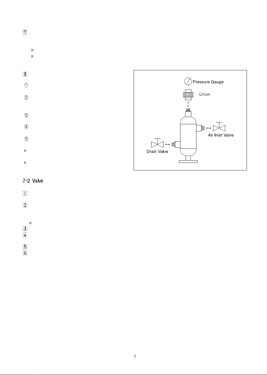
Install the Air Chamber at the close range
within 1~2 meters from the metering
pump.
Fix the Air Chamber with support.
For safety, do not install a valve between
the metering pump and the Relief Valve .
Make sure that the inlet/outlet direction of
the BV and RV is not installed reversely.
Install the pressure gauge on the
discharge piping
Install the pipe & valve for draining
certainly.
Take precautionary measures against the
freezing of the liquid in winter
When the needle of the pressure gauge is swayed over twice as wide as the usual one or
vibration occur in the piping or the pulsation of the discharge side becomes bigger, should
supplement air into the Air Chamber
Weekly inspection is recommended
If the operating pressure exceeds 5 bar, the dissolution speed of the air into the liquid will be
accelerated and the function of air chamber cannot be maintained. At this situation, should
supplement air into the Air Chamber frequently
When supplementing air into the Air Chamber,
please keep the following procedures
After stop of pump, close both front valve and
rear valve of the Air Chamber.
Slowly unfasten the upper plug and drain the
air. When the air is completely drained, fasten
upper plug.
Unfasten the lower plug and unfasten the
upper plug again in order to drain the liquid.
Fasten the upper & lower plug firmly, when the
flow of liquid comes to a stop.
Open both front valve and rear valve of the Air
Chamber.
In case of dangerous liquid, install valves
instead of a plug, together with a drain pipe.
If the pressure gauge should be installed, use
Union.
Setting pressure of Back Pressure Valve and Relief Valve is set at our factory with the clean water.
So you have to readjust it according to actual flow rate & actual pressure, if necessary.
If you want to adjust setting pressure, unfasten the housing cap counterclockwise and, if you fasten the
valve guide(rear) & the control bolt clockwise, setting pressure will get higher. On the contrary, if you
unfasten the valve guide(rear) & the control bolt counterclockwise, setting pressure will get lower.
Adjust setting pressure by watching the pressure gauge on the piping while the pump is working.
If the setting pressure is correctly adjusted, fasten the housing cap.
If you want to remove foreign substance from the valve or change a diaphragm, close the front piping of
the valve and drain the liquid.
Then, unfasten the bolts and disassemble the housing& the diaphragm from the valve.
After removing the foreign substance, make sure that you re-assemble the diaphragm in such a way that
the PTFE-coated side of the diaphragm faces the main body .

Trouble Cause Troubleshooting
Can t reduce pulsation Air is insufficient in the Air Chamber Refill air.
Back pressure is insufficient at the Adjust the Back Pressure
discharge side Valve or Control Valve
Vibration of the piping Air is insufficient in the Air Chamber refill air.
Liquid cannot be Relief valve is being operated to Remove the cause of abnormal
discharged abnormal pressure pressure(closing or freezing of
valve)
Liquid is released before Foreign substance are accumulated Remove the foreign substance
the setting pressure is Diaphragm is damaged and wash
reached
If the product is reconstructed arbitrarily or the undesignated parts are used into the pump,
CHEONSEI will not warrant and CHEONSEI is not responsible for any expense caused by accident or trouble.
Warranty period is one year from purchase date.
During warranty period, repair or change of product is free of charge, if trouble or damage of pump
due to design or manufacturing of CHEONSEI. ( Consumable parts are excluded.)
Repair or change product due to following reasons will be charged regardless the warranty period.
Trouble or damage of product expired warranty period.
Trouble of using by careless handling.
Trouble or damage due to using non-designated part & reconstructing the pump arbitrarily.
Trouble by fire or natural disaster.
No Part Name Q ty
1 Plug 3
2 Socket 3
3 Packing 3
4
End Cap(Lower)
1
5 Pipe 1
6 Plate 1
7
End Cap(Upper)
1
8 Pipe 1
9 Flange 1
No Part Name Q ty
10 Casing(Lower) 1
11 Casing(Upper) 1
14 Flange 1
15 Bolt(Hex.) 4/8
16 Bolt(Hex.) 4
17 Nut(Hex.) 4/8
18 Nut(Hex.) 4
23 Gasket 1
24 Gasket 1
No Part Name Q ty
1 Plug 3
2 Socket 3
4
End Cap(Lower)
1
5 Pipe 1
6 Plate 1
7
End Cap(Upper)
1
8 Pipe 1
9 Flange 1
When the product is sent to factory for repair service, clean out inside of product.
Contact to CHEONSEI or local distributor as shown on back of the manual, if you have any problem or questions.
If you want to repair, please inform the following.
Model Name & manufacture number written in name plate
Used period, operation condition, operation status, and transfer liquid
If warranty period is over, it may charge according to repair part. Please contact with sales agent for
more information.
Minimum retention period of parts for repair is 5 years from the date of production.
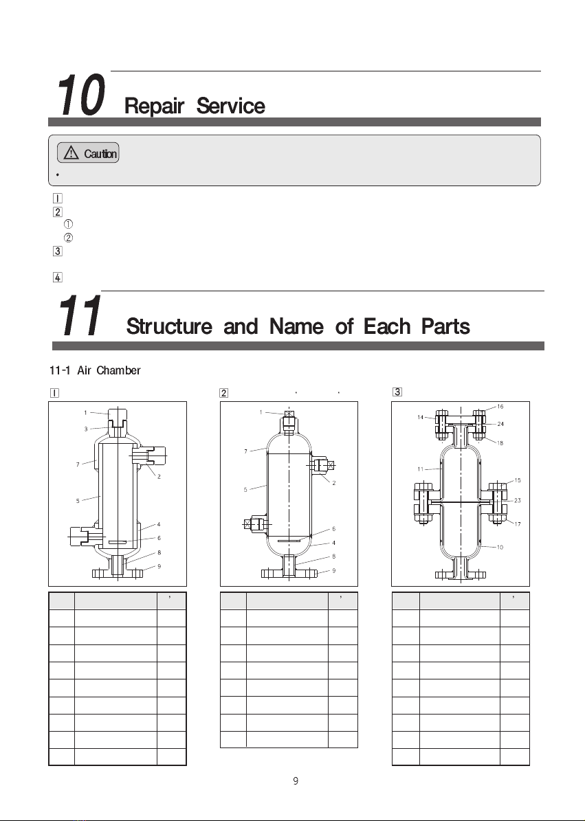
Model : AC-V15A~V50A Model : AC-S 615A~S 650A Model : AC-F15A~F50A
No Part Name Q ty
1 Main Body 1
2 Valve Housing 1
3 Diaphragm 1
4
Valve Guide(Front)
1
5
Valve Guide(Rear)
1
6 Spring 1
7 Housing Cap 1
8 Joint Pipe 2
9 Flange 2
10 O-ring 1
12 Bolt(Hex.) 4
13 Washer(Flat) 8
14 Washer(Spring) 4
15 Nut(Hex.) 4
17 O-ring 2
No Part Name Q ty
1 Main Body 1
2 Valve Housing 1
3 Diaphragm 1
4
Valve Guide(Front)
1
5
Valve Guide(Rear)
1
6 Spring 1
7 Housing Cap 1
8 Joint Pipe 2
9 Flange 2
11
Control Bolt(Hex.)
1
12 Bolt(Hex.) 4
13 Washer(Flat) 8
14 Washer(Spring) 4
15 Nut(Hex.) 4
16 Nut(Hex.) 1
17 O-ring 2
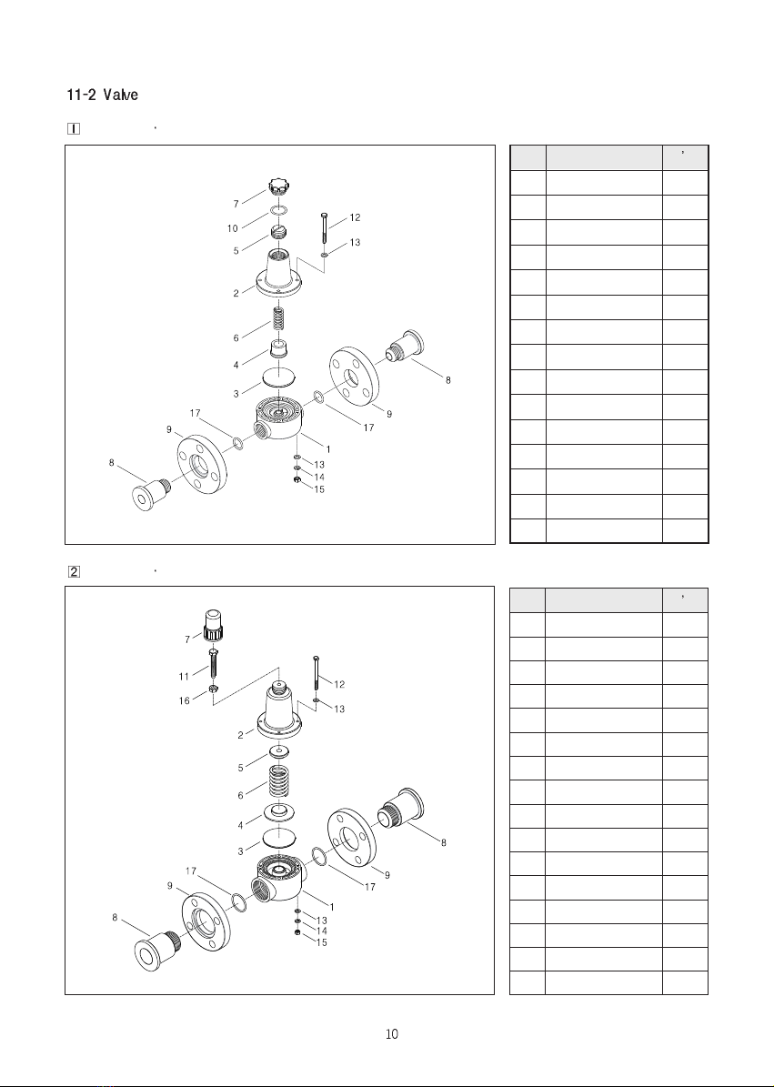
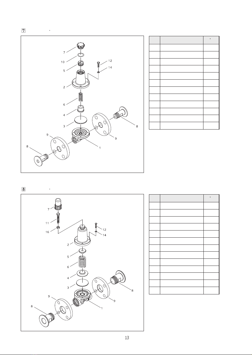
Model : BV RV-V15A,V20A-F
Model : BV RV-V25A~V50A-F
No Part Name Q ty
(1) Main Body (1)
2 Valve Housing 1
3 Diaphragm 1
4 Valve Guide(Front) 1
5 Valve Guide(Rear) 1
6 Spring 1
7 Housing Cap 1
(8) Joint Pipe (2)
(9) Flange (2)
10 O-ring 1
12 Bolt(Hex.) 4
13 Washer(Flat) 8
14 Washer(Spring) 4
15 Nut(Hex.) 4
Model : BV RV-F15A, F20A-F
No Part Name Q ty
(1) Main Body (1)
2 Valve Housing 1
3 Diaphragm 1
4 Valve Guide(Front) 1
5 Valve Guide(Rear) 1
6 Spring 1
7 Housing Cap 1
(8) Joint Pipe (2)
(9) Flange (2)
11 Control Bolt(Hex.) 1
12 Bolt(Hex.) 4
13 Washer(Flat) 8
14 Washer(Spring) 4
15 Nut(Hex.) 4
16 Nut(Hex.) 1
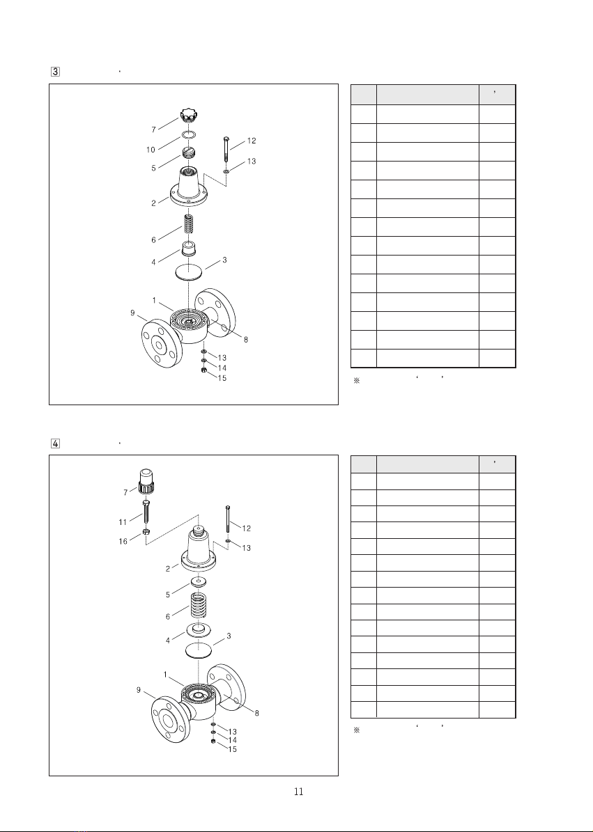
Model : BV RV-F25A~F50A-F
In case of (No.) , it is all-in-one
struction.
In case of (No.) , it is all-in-one
struction.

No Part Name Q ty
1 Main Body 1
2 Valve Housing 1
3 Diaphragm 1
4 Valve Guide(Front) 1
5 Valve Guide(Rear) 1
6 Spring 1
7 Housing Cap 1
10 O-ring 1
12 Bolt(Hex.) 4
13 Washer(Flat) 8
14 Washer(Spring) 4
15 Nut(Hex.) 4
Model : BV RV-V(F)15A, V(F)20A-T
No Part Name Q ty
1 Main Body 1
2 Valve Housing 1
3 Diaphragm 1
4 Valve Guide(Front) 1
5 Valve Guide(Rear) 1
6 Spring 1
7 Housing Cap 1
11 Control Bolt(Hex.) 1
12 Bolt(Hex.) 4
13 Washer(Flat) 8
14 Washer(Spring) 4
15 Nut(Hex.) 4
16 Nut(Hex.) 1
Model : BV RV-V(F)25A~V(F)50A-T
No Part Name Q ty
1 Main Body 1
2 Valve Housing 1
3 Diaphragm 1
4 Valve Guide(Front) 1
5 Valve Guide(Rear) 1
6 Spring 1
7 Housing Cap 1
8 Joint Pipe 2
9 Flange 2
10 O-ring 1
12 Bolt(Hex.) 4
14 Washer(Spring) 4
Model: BV RV-S15A, S20A-F
No Part Name Q ty
1 Main Body 1
2 Valve Housing 1
3 Diaphragm 1
4 Valve Guide(Front) 1
5 Valve Guide(Rear) 1
6 Spring 1
7 Housing Cap 1
8 Joint Pipe 2
9 Flange 2
11 Control Bolt(Hex.) 1
12 Bolt(Hex.) 4
14 Washer(Spring) 4
16 Nut(Hex.) 1
Model: BV RV-S25A~S50A~F

No Part Name Q ty
1 Main Body 1
2 Valve Housing 1
3 Diaphragm 1
4 Valve Guide(Front) 1
5 Valve Guide(Rear) 1
6 Spring 1
7 Housing Cap 1
10 O-ring 1
12 Bolt(Hex.) 4
14 Washer(Spring) 4
Model: BV RV-S15A, S20A-T
No Part Name Q ty
1 Main Body 1
2 Valve Housing 1
3 Diaphragm 1
4 Valve Guide(Front) 1
5 Valve Guide(Rear) 1
6 Spring 1
7 Housing Cap 1
11 Control Bolt(Hex.) 1
12 Bolt(Hex.) 4
14 Washer(Spring) 4
16 Nut(Hex.) 1
Model: BV RV-S25A~S50A~T

40, ANSANTECOM-GIL, SANGNOK-GU,
ANSAN-SI, GYEONGGI-DO, KOREA
Phone : +82-31-508-1003
Fax : +82-31-419-3223
Homepage : www.cheonsei.co.kr
This manual suits for next models
5
Other Cheonsei Water Pump manuals


Popular Water Pump manuals by other brands

Gardner Denver
Gardner Denver Welch WOB-L 2522C-02 Operation manual

Gardena
Gardena 4000/2 automatic 1742 operating instructions

Hyundai power products
Hyundai power products HBP1200 Original instructions

Grundfos
Grundfos Redi-Flo3 Product guide

PEDROLLO
PEDROLLO VSP manual

Metso
Metso Orion Series Operation & maintenance manual


Viking pump
Viking pump 4924A Series Technical & service manual

Becker
Becker Variair VASF 2.80/2-0.AC230 operating instructions

SKF
SKF Lincoln P653S User and maintenance instructions

Berkeley
Berkeley 6D owner's manual

GRE
GRE PP051 instruction manual

Watson Marlow Pumps
Watson Marlow Pumps 530 Du Installation, operating and maintenance manual