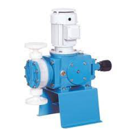
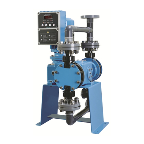
Cheonsei KEMPION PDS Series User manual

PDS Series
Pulseless Diaphragm Pumps
Instruction Manual
www.cheonsei.co.kr
METERING PUMPS


3
Thank you very much for purchasing Cheonsei PDS pumps.
Before beginning operation, please read this instruction manual carefully. Correct
handling, repair, & maintenance are described easily. Please use this pumps safely
to be guaranteed performance & long life of the pump after reading this instruction manual.
Please keep this instruction manual at the place where you can see it easily.
1. Notice for Safety ………………………………………………………………… 4
2. Conrmation of Product ………………………………………………………… 5
3. General …………………………………………………………………………… 5
4. Model Code ……………………………………………………………………… 6
5. Standard Liquid End Material …………………………………………………… 6
6. Specication ……………………………………………………………………… 7
7. Performance Curves ……………………………………………………………… 8
8. Operation Principle and Structure ……………………………………………… 8
9. Installation ………………………………………………………………………… 9
10. Operation ……………………………………………………………………… 12
11. Maintenance …………………………………………………………………… 13
12. Cause of Trouble and Troubleshooting …………………………………… 15
13. Replacement of Parts ………………………………………………………… 16
14. Consumable Parts and Spare Parts ………………………………………… 18
15. Warranty ……………………………………………………………………… 18
16. Repair Service ………………………………………………………………… 18
17. Accessories …………………………………………………………………… 19
18. Structure & Part Name of Check Valve ……………………………………… 19
Contents
Introduction

4
1-1 Introduction
•
To use the products safely, the signs are showed on the manual like below.
•
As it is a matter of safety, please be sure to keep the directions in manual.
•
Each symbol and its meaning are described as below. Regarding the BLDC M/C UNIT supplied
by us, always follow all directions (i.e., warning, caution etc.) described in the instruction manual
specially provided as well as warnings and cautions in this manual.
Warning
Person death or serious injury will be occurred, if warning is not kept by wrong handling.
Caution
Person injury or property damage will be occurred, if caution is not kept by wrong handling.
1-2 Cautions for Operating Condition
Caution
•Do not use this pump for other purposes except liquid injection. Otherwise it may cause trouble.
•
Do not use for kinds of liquid which cause damage to liquid end parts. Please keep the
followings,
otherwise it may cause trouble.
Ambient temperature: 0~40℃
Temperature of the handling liquid : 0~50℃ if Liquid End material is PC or FC
0~80℃ if Liquid End material is SS
Piping pressure : Below the max. discharge pressure indicated on the Specications.
※ Pressure over the allowable one may cause damage to the product, so install safety valves
(i.e relief valve) and strainers at pipes.
1-3 Cautions for Handling Condition
Warning
•Install this pump beyond the reach of children and/or unauthorized person
•
Turn off the power and stop the pump & other equipments when repairing or disassembling pumps.
If power is on during work, it may cause electric shock.
•
Please do not operate when the discharge and suction valve are closed. Also, do not close the valve
during operation. Pump and piping may be damaged
•
Be careful not to insert ngers or any foreign substances into rotating or reciprocating objects during
operating pump. If you touch it during operation, you may get injury.
•
Do not touch with wet hands. Electric shock may occur.
•
Use only designated parts. If undesignated parts are used to the pump, it may cause accident &
trouble.
•
Do not arbitrarily reconstruct the pump and BLDC M/C UNIT. If the pump is arbitrarily reconstructed, it
may cause accident & trouble, and we are not be liable for the problems.
1
Notice for Safety

5
Caution
•Do not use damaged pump. It may cause accident.
•
Do not install pump in the heavy moist or dusty place. It may cause electric shock and trouble.
•
Do not touch motor with bare hands during operation. High temperatures can cause burns.
•
Wear suitable protective clothing(gloves, mask, goggles, working clothes, & etc.) during
assemble and disassemble work when pumping hazardous liquids or uncertain liquids.
•
Do not use power other than that specied in the motor nameplate. Otherwise, it may cause
malfunction or re.
•
Pump should be properly grounded. If pump is not grounded, it may cause electric shock.
•
Work after releasing pressure from discharge piping and remove liquid from Liquid End Part
prior to repair or maintenance of pump.
•
Pump may be damaged when ambient temperature go down below freezing pont of liquid.
Be sure to remove the liquid in the pump and piping after operation stop. Provide adequate
protection against freezing the pump and piping during winter season.
•
Make proper protection in consideration of indeliberate leakage from damage of pump & Piping.
•
Dispose of waste pump in accordance with related national law.
2-1 Check Point When Unpacking
Please check following points immediately after receiving the pump.
If the defect is found from pump, please request it to local agent or Cheonsei.
Is specication correct as ordered?
Is there any missing parts?
Is there any visible damage caused by vibration or shock during transport?
Is there any loosened bolt or nut?
2-2 Standard Accessories
Instruction Manual ………………………………………………… 1 Copy
Mounting bolts (M10×40L Including Washers & Nuts) ………… 4 Set
These pumps are a pulseless diaphragm metering pump which pulse rate of discharge capacity is
reduced. Chemical is sucked and discharged by reciprocating diaphragm which is attached to Rod by
special cam after reducing the rotation of motor by Gear. In case of BLDC M/C UNIT installed, stable
capacity is maintained in low-speed, and feedback is quick.
2
Confirmation of Product
3
General

6
NO Code PC FC SS
Part Type
➊Head PVC PVDF STS316
➋Diaphragm PTFE
➌Check Ball CERAMIC STS316
➍Ball Guide PVC PVDF STS316
➎Ball Stopper PVC PVDF STS316
➏Joint PVC PVDF STS316
➐ O-ring?Packing FKM FEP(+SIL)
Notes) 1. In case of special materials other than the standard, please contact separately.
2. Above standard material can be revised for improvement without prior notice.
PDS
-
10
-
S S
-
F W S
-
0 1
➊➋➌-a ➌-b ➍➎➏➐➑
➊MODEL PDS (PULSELESS DIAPHRAGM METERING PUMP)
➋DIS. CAPACITY 5 : 5.5 L/min 10 : 10.5 L/min
➌LIQUID END MATERIAL a. Head(P : PVC, F : PVDF, S : STS316, X : Special)
b. Check Ball(C : CERAMIC, S : STS316, X : Special)
➍CONNECTION F : Flange, C : Clamp, X : Special
➎VALVE TYPE W : Standard, V : High Viscosity
➏POWER S : 3Phase/380~480V, A : 3Phase/1Phase/200~240V, X : Special
※ BLDC motor is standard. If requested, motor for inverter is available.
➐OPTION(LIQUID END) 1 : Diaphragm Damage Detection Device 0 : None
➑REMOTE CONTROL 1 : Inverter, 2 : BLDC M/C UNIT(Auto)
3 : BLDC M/C U NIT(Manual), 0 : None
4
Model Code
5
Standard Liquid End Material

7
PDS - 5 PDS - 10
Max. Discharge
Capacity
L/min (L/h)
5.5 (330) 10.5 (630)
Max. Discharge
Pressure
bar(PSI)
5 (72.5)
Pulse Rate(F/S) % ± 3.0
Stroke Length mm 8.5
Max. Stroke Number spm 96
Connection
(Discharge /
Suction)
FLANGE KS 10K 25A / KS 10K 25A KS 10K 25A / KS 10K 40A
CLA,MP 1.5S 25A / 1.5S 25A 1.5S 25A / 1.5S 32A
Temperature of the
Handling Liquid ℃ SS, FC : 0~80℃ / PC : 0~50℃ / Ambient temperature : 0~40℃
Max. Viscosity of the
Handling Liquid cp 20,000
Controller :
BLDC M/C UNIT
Driver
Power 200V: 1Phase/3Phase/AC200~240V , 400V:
3Phase/AC380~480V
Input
(operation)
Signal
REMOTE: 4~20mA, LOCAL: By the keypad ▲& ▼
Remote control (REMOTE RUN/STOP)
Output Signal ISOLATED 4~20mA/Operating & Over Current(Err)
Relay Contact Output
Effective Flow Control
Range of Discharge
Capacity
Effective Flow Control Range of Discharge
Capacity
Others RATIO (Setting range: 0~100% based on remote
input signal)
Power
0.25KW / FR63 0.55KW / FR71
8 Poles Brushless DC / Max. rpm : 1750 / Insulation Class : F
Painting Munsell No. 0.6PB 4.8/10.6 (However, motor follows the manufacture’s
Weight
kg 48 56
Notes) 1. Max. capacity is the value when Max. discharge pressure is applied(with room
temperature & pure water).
2. Suction connection is KS10K40A, 1.5S 32A for high viscosity type(FV, CV).
3. The weight is based on a standard motor and a ange connection(SS Type).
4. Specications above can be changed for improvement without prior notice.
5. Please refer the instruction manual enclosed separately for BLDC M/C UNIT operation.
6
Specification

8
The rotation of the Motor is reduced by the Worm Gear and the rotational motion is converted to
reciprocating motion by Eccentric Device(Eccentric Cam, Slider, Rod & etc.). This reciprocating movement
changes the volume inside the pump through the diaphragm connected to its Rod, causing the pump to do
its pumping action as results of the change of the volume inside the pump and the check ball installed at
the head of the pump. The Smoothy metering pump removes pulsation through the ow of uid having a
trapezoid discharge waveform produced by a high-precision constant-velocity cam which is continuously
discharged through the two liquid ends having a 180o phase difference.
8
Operation Principle and Structure
Gearbox
flange
Motor
Joint
Cover Attachment
Gearbox
Bed
Head
A B
Cam Guide shaft
Diaphragm(rear) Discharge
Suction Head
Check ball
Diaphragm(front)
Slider Diaphragm
rod
40
1800
600
1200
020
2400
3000
3600
4200
4800
5400
6000
10060 80
1 ba r
5 ba r
40
3600
1200
2400
020
4800
6000
7200
8400
9600
12000
10800
10060 80
1 bar
5 bar
7
Performance Curves
•Condition: Clean Water, Room Temperature, Suction Head - (1M) BLDC TYPE
●PDS-5 ●PDS-10
Notes) 1. Above performance curves were tested at our testing equipment under the xed condition(Clean Water,
Room Temperature, & 1m of Suction Head). Therefore, performance curves can be somewhat different in
accordance with condition of job site after installation.
2. Check the discharge capacity(drawing the performance curve) in test operation after installation because
discharge capacity can be changed according to piping condition and chemical’s characteristic.

9
9-1 Installation Place
If possible, install the pump lower than the minimum level of the tank.
Take sufcient space around the pump to facilitate maintenance or repair and also the motor and
wiring should be connected safely in consideration of ooding.
The pump should be installed at the place where is at surface and not affected by vibration of
other equipments.
Pump should be installed on the concrete foundation or on the pedestal can be sufficiently
supported. Also, check the level with a leveling instrument so that pump can be installed
horizontally.
9-2 Piping (Universal Precautions)
Decide the piping system which can sufciently satisfy suction & discharge condition.
Piping should be short and less bending as far as possible and be careful not to make the cavity
at which air stay.
Install piping support lest piping load fall on the pump. Especially, in case of liquid end material of
PVC, be careful about handling.
Flexible joints are recommended to use to pump Liquid End Part.
●Discharge waveforms of the pulseless metering pump
9
Installation
Discharge
Rate
One rotation
A+B A+B +
A B =A
B
0
A B The rate of discharge is kept
uniform by overlapping the
A and B section one anther.
Caution
•Do not install this pump at the place where ambient temperature is higher than 40℃ or lower
than
freezing point. If the pump is installed at the place, internals of pump may be damaged.
•
Do not install pump in place with heavy moisture and dust, or in place with rain, and wind.
It may cause electric shock and trouble.

10
B e c a r e f u l t h a t p u m p i s n o t t o b e
influenced with thermal stress of piping
when transferring hot liquid or cold liquid.
Don’t make U shaped bend in the piping
when transferring easily precipitable slurry.
Install a ushing pipe line for maintenance
and inspection when transferring viscous
liquid,
poisonous liquid, or coagulative liquid.
Choose the piping material that has
sufcient corrosion resistance to the liquid
and can endure the pressure applied in the
piping.
Connect piping after ushing the inside of
piping cleanly and remove the inspection
sticker for preventing entrance of foreign
substance on the discharge port.
Protect the piping with insulating material
or keeping warm device, if the liquid may
freeze inside of piping. In addition, Install
drain valve at the suction & discharge side
in order to drain the
liquid inside piping after operation stopped.
9-3 Suction Piping
Suction piping is made with drop method as far as possible. Also, the diameter of the suction
piping should be larger than or same with the suction diameter of the pump.
Carefully connect the joint of suction piping in order to prevent air inow into the piping.
Discharge rate of pump can be destabilized by air Inow into the piping.
Make piping length of suction side as short as possible. If it is too long, cavitation occurs and
regular discharge rate can‘t be assured.
Install a strainer on the suction piping because it make unstable performance that foreign
substances ows into pump head.
9-4 Discharge Pipe
Safety valve should be installed at a place near to discharge pipe of the pump and do not install
any other valves between the pump and the safety valve.
Use a discharge pipe of which internal pressure is higher than the set value of the safety valve.
Also, carefully t the joint of the discharge pipe.
If discharged at the pressure below than atmospheric pressure, keep the pipe end higher than the
water level of the tank or install the back pressure valve to prevent siphon phenomenon.
(The pulse rate could be increased after installing the back pressure valve, so consult an expert
before installing it.)
Install pressure gauge for daily inspection of the discharge pressure.
9-5 Electrical Wiring
Warning
•
Do not touch with wet hands. Electric shock may occur.
Safty Valve
Pressure
Pressure
Suction
Discharge
Drain Valve
Pump
Drain Valve
Y-Straner
TANK
Valve Relief Valve
Gauge
Valve

11
9-6 Diaphragm Damage Sensor
A detector sensing damage to the diaphragm is added to the PDS pump series, which is designed to
sense any damage to the diaphragm during pump operation and stop the pump to protect the pump
system. A sensor is mounted on the gear box flange and the front flange; when the diaphragm gets
damages, it senses uid leaked at its back and sends a signal. This system is easy to install.
The BLDC M/C UNIT or a separate inverter receives the detection signal and brings the pump to a stop.
The diaphragm sensor and the BLDC driver
are wired at the factory before the product is
shipped.
The lamp gets lit when the sensor detects any
damage to the diaphragm. The operator can
monitor damage to the diaphragm using the
trip of the BLDC driver terminal block.
When an induction motor is used, the operator
can monitor the condition of the diaphragm
using the relay of the detector. Do wiring to the
terminal block of the detector in reference to
the following instruction.
Input Power : DC24V 300mA
Relay Spec. : SPDT 2A DC30V
Cable Standard : AWG18~26
Cable Connector Standard : PF 3/4″
P(+), N(-) : Input Power
E : Ground
NC, COM, NO : Relay
Caution
•
After checking the power specification of the BLDC M/C UNIT before wiring, connect the pump to the
rated power. If not, it may cause trouble and fire.
•
Pump should be properly grounded in order to prevent electric shock.
•
Entrust the wiring to electrical engineer.
•
Install regulated Magnet Switch and Thermal Relay for the adjustment and maintenance of the pump.
•
Use standardized parts in wiring and fully pay attention to safety in accordance with the technical
standard & wiring regulation of the electrical equipment.
•
Reverse rotation of the motor causes trouble, so wire the motor’s power so that the motor’s
rotation direction is clockwise.(This is only for Inverter and general motor.)
Front flange
Sensor Cable
Terminal
box
BLDC M/C
Unit
Gearbox
flange

12
Caution
•
Do not use the controller (BLDC M/C UNIT) below 10%.
Warning
•
Do not operate when suction valve and discharge valve are closed or do not close suction
valve and discharge valve during operation. Pump and piping may be damaged with excessive
pressure rising and liquid may spout when operation under valve closing.
10-1 Preparation
When operating pump for the rst time after installation, please check the following conditions.
Check if there is oil leakage caused by any damaged parts or loosened bolt.
Check the oil gauge to see if the driving part of pump is lled with the oil of regulated amount.
(The normal position of the oil level is the middle red point of the gauge.)
Check if all of accessories, liquid to be transferred, and power supply necessary for pump operation are ready.
10-2 Operation
Open the suction and discharge valves.
Check the rated power and turn on the pump. Check if the motor fan rotates clockwise.
(This is only for inverter or general motor)
Open the discharge side up to the atmospheric pressure, and increase the discharge amount slowly
up to 50%. Connect to the ange of the discharge side, and then operate test run for 30minutes.
Caution) When the ambient temperature is low, overload may occur temporarily due to low
temperature of lubricant. Wait until the lubricant temperature increases with no load.
If there is no error found during test run, set the discharge capacity to 100% and increase the
pressure of the discharge side up to the setting one. Check if the BLDC controller works properly
and if every part works properly.
10-3 Control of discharge amount
The discharge amount can be controlled by the controller (BLDC M/C UNIT).
The controller can operate within 10 ~ 100%, but its effective ow rate-controllable range is
20 ~ 100%. (Within 20 ~ 100%, the discharge amount is stable)
10-4 Restart of pump
In case of stop pump operation for short period(less than 1 week), run the pump at a desired stroke
length & prescribed discharge pressure after air bleed operation.
In case of stop pump operation for a long period(more than 1 week), the pump should be run at
atmospheric pressure of discharge side for several minutes before going into normal operation.
Do not start regular operation before above warming up.(Set the controller to 50%)
10
Operation
Caution
•
Some water may be remained in the liquid end part of pump after nal performance test.
In case of use for some liquids reacting radically to water, remove water in the pump and dry
the pump necessarily.

13
Warning
•Turn off the power and stop the pump & other equipments when repairing or disassembling
pump,
otherwise it may cause electric shock.
•
Be careful of big accidents caused by inserting ngers or cloth in rotator.
Caution
•Wear suitable protective clothing during assembly and disassembly work
•
Work after releasing pressure from discharge piping and remove liquid from Liquid End Part
prior to repair or maintenance of pump.
It is concern that pump is damaged by freezing during winter season. Without regard to stop perioed of
operation, drain the liquids in the piping and pump by operating dry run after opening the drain valve
on the suction piping.
In case of stop pump operation for a long period(more than 1 week), the pump should be run at
atmospheric pressure of discharge side for several minutes before going into normal operation.
… Do not start regular operation before above warming up.(Set the controller to 50%)
It is concern that pump is damaged by freezing during winter season. Without regard to stop perioed of
operation, drain the liquids in the piping and pump by operating dry run after opening the drain valve
on the suction piping.
10-5 Conrmation of discharge amount
If pump has no problem, check the discharge volume under actual running condition with measuring
device such as mass cylinder.
If discharge volume had no uctuation after repeated measurements, the pump is judged to be running
normally.
When the discharge amount increases/decreases by changing the motor speed, measure the
discharge amount one minute or more after the change.
Note) If you request the test report, we submit the test report which has been performed at normal
temperature and with clean water. The result may vary depending on on-site pipes and
transferred liquid.
10-6 Pulse rate increase
The pulse of the metering pump largely depends on pipes and transferred liquid. (Since the factory test
condition is not same as your on-site condition, the result may be different.)
Besides, if the pump operates after a long stop, its metering performance and pulse rate may change due
to adherence of transferred liquid to the check valve etc., so, always clean the inside of the wet side to
keep it for a long stop duration. The increase of the pulse rate after the warranty may result from life time
of parts, so please refer to “14. Consumable Parts”. For other questions, please contact us.
11
Maintenance & Inspection
11-1 Inspection before operation
Check the level of liquid tank and, if it is insufcient, supplement the liquid.
Check if the suction & discharge valve are opened.
Check if piping is safe and undamaged.
Check electrical wiring if there are no electrical short & disconnection.

14
11-2 Inspection during operation (Daily inspection)
Check the level of liquid tank and, if it is insufcient, supplement the liquid. Specially, be careful in
the process which handle the chemical solution or required Air-Free circumstance.
Check if liquid or air is leaked out the Joint or other parts. If necessary, fasten it again.
If leakage doesn’t stop, check O-ring and/or Packing of each parts and replace the damaged
O-ring and/or Packing with new one.
Check if noise sounds from the motor or pump.
Check if the oil in the driving part is sufcient or leaky. If insufcient, rell the oil up to regulated
level of the oil level gauge.
Check if there is no problem in the setting discharge rate & discharge pressure.
Check if the pressure gauge is normal.
If there is a standby pump, operate it periodically. Maintain it so that it can work whenever.
11-3 Long-term stop
Wash inside Pump Head of suction side and ush water or cleansing solution through Pump Head
for about 30 minutes.
Put the cover on the pump to protect the pump from dust and/or corrosion.
Check foreign substances lay on the Check Valve before restarting the pump.
11-4 Other Maintenance
When diluted liquid is used at freezing place in the winter, install heat tracing and humidier to
prevent the pump from freezing because it causes the damage of the pump & other devices with
freezing on the liquid end part of pump and inside piping.
Clean the inside of tank and joint every 3 months at least.
11-5 Supplement of oil
Change of oil in the driving part
①Changing interval
Change oil after 500 hours when initial operation after buying it, and thereafter, change oil
every 4,000 hours of continuous operation. However, when emulsication or deterioration of
the oil occurs, change the oil immediately.
②Changing method
•Turn the dial to 0%, loosen the (square)
plug with spanner, and drain the used oil.
Next, clean the inside with ushing oil.
•
After fastening the plug, refill new oil
slowly through the oil inlet(Oil Cap) up to
the regulated level(Red points) of the oil
level cap
MODEL PDS-5,10
Suitable oil amount 950 mL
③ Recommended oil
•Shell’s Omala #220 (※)
•Mobile’s Gear oil #630
•Other gear oil with the viscosity grade of
ISO VG220, SAE90
Note) (※) means the oil used by us.
Oil cap
Oil Level
cap
Drain
Plug

15
Problem Cause Action
Pump does
not work
The circuit breaker opens or the fuse is burnt
Look into the cause and take action
Cables are broken Connect or replace
Wrong wiring Check the wiring diagram
Low voltage Investigate and take action
Poor insulation Replace
The bearing becomes damaged Check and replace
The reduction gear gets damaged Check and replace
Pump work,
but does
not discharge
uid
The supply tank is empty. Rell uid
Cavitation occurs in the uid Check the NPSH and take action
Air gets in at the suction-side pipe Inspect and repair piping
The suction pipe gets clogged
Wash piping and check the condition of the uid
The ball seat gets blocked by foreign matter
Wash & check and then install the strainer
The safety valve leaks
Re-adjust the preset pressure. Inspect and repair
Pump produces
insufcient
amount of
discharge
The motor rotates very slowly
Check the wiring for voltage and frequency
The amount of discharge was not calibrated
correctly
Check the measurement method and measuring
instruments
Insufcient suction pressure
Increase the water level of the supply tank and
enlarge the pipe’s diameter
Insufcient discharge pressure Install a back pressure valve
The suction pipe gets clogged Clean the piping and check if the fluid flows
properly
Air comes into the suction pipe Inspect and repair the piping
The ball seat and/or check ball become dirty
or damaged Clean or replace
The piping or pump leaks at joints Inspect and repair
The O-ring of the valve gets damaged or
defective Replace
The constant velocity cam gets worn Replace
The diaphragm becomes obsolescent or
damaged Replace
Cavitation occurs in the uid Examine the NPSH and take action
Lubicant leaks The oil seal gets damaged Replace
The lubricant gets contaminated Check for causes and replace
Fluid leaks a lot
The pressure gauge has broken down Replace
The diaphragm gets damaged Replace
The valve’s O-ring gets impaired and in poor
condition Replace
There is much
noise and
excessive
heat
The atmospheric temperature is high Improve the installation condition
The suction pipe is clogged Wash the pipes
The bearing is damaged Check and replace
The reduction gear is damaged Check and replace
Cavitation occurs in the uid Examine the NPSH and take action
Lubricant is insufcient or overowing Drain or rell the lubricant to the specied level
The constant velocity cam gets worn Check and replace
The lubricant used is of different specication Replace it with a specied lubricant
The motor gets overloaded Inspect and adjust the discharge pipe system
The power supplied is improper Check and repair
The drive does not work smoothly Check if it has any driving parts worn out or
corroded.
Notes 1. Conduct inspections regularly to keep the pulse rate stable.
2. Refer to the User Manual for any problems relating to the BLDC M/C unit, and contact us if you want
to have more information.
12
Cause & Action of Problem

16
13-1 Replacement of Ball Stopper,
Ball Guide, and Check Ball
Disassembly
①Unfasten the pipes of the suction and discharge
sides.
②Unfasten cap nut of suction and discharge sides,
and take out each part. Be careful of any liquid
which remains inside the pump may come out.
③
Inspect the each part of Check Valve, and clean
or replace.
Assembly
①Refer to 18. Structure and Name of Check
Valvefor assembly.
② Fasten tightly after connecting to companion
piping.
13-2 Replacement of Diaphragm
Disassembly
①Unfasten the pipes at the suction-side
and discharge-side joints.
②Disassemble the joints in reference to
13-1.
③Unscrew the wrench bolts and
separate the front cover.
④Loosen the hexagon nut holding
the guide bar using a spanner and
disconnect the bar.
Caution
•
Assemble while paying attention to the direction of the value (top: ball stopper). If the order is
reversed, the uid ows reversely, when the pump may get damaged.
Warning
•Wear the protective equipment because any liquid which remains inside the pump may come out
during
disassembly and cause fatal injury to human body.
※Refer to 18. Structure and Name of Check Valvefor assembly and disassembly.
Valve Adapter
Check Valve
Joint
Joint Cover
Cap Nut
Bolt
Cover Nut
Guide
bar
13
Replacement of Parts

17
⑤
Unscrew the head fixing bolt using a spanner to separate each part such as front flange,
sub-ring, and head.
⑥
Unfasten the diaphragm rod with a spanner and then disassemble the front diaphragm.
⑦
Rotate the motor slowly and hold the outer part of the diaphragm when the stroke length of the
back diaphragm reaches 100%. At this time, rotate it counter-clockwise to disassemble the
diaphragm.
⑧
When the diaphragm displays any sign of abrasion or impairment, replace it with a new one.
Assembly
①Assemble it in the reverse order of disassembly.
② When the pump’s head bolts are tightened, be sure to give the head xing bolts uniform force
(torque) in the diagonal direction. ※ Recommended torque: 9.8N?m (100kgf·cm)
Bolt
Front
flange
Backup
Diaphragm
Diaphragm
rod
Sub Ring
Diaphragm(front)
Head
Diaphragm(rear)
Sub Ring
Backup
Diaphragm
Diaphragm
rod
Gearbox
flange

18
Warning
•If the pump is reconstructed arbitrarily or the undesignated parts are used into the pump, Cheonsei
will not warrant and Cheonsei is not responsible for any expense caused by accident or trouble.
14-1 Consumable part
Part Name Q’ty Replacement
intervalCheck valve 4 1 year
Diaphragm 2 4,000 hours
O-ring (liquid end) 8 1 year
Oil Seal 3 1 year
Reduction gear 1 1 year
Velocity cam 1 1 year
14-2 Spare Part
•Spare part(s) for 3 years : bearing / Spare part(s) for 3 years or longer: motor
Warranty period is one year from purchase date.
During warranty period, repair or change of pump is free of charge if trouble or damage of pump due
to design or manufacturing of Cheonsei. (※ Consumable parts are excluded.)
Repair or change product due to following reasons will be charged regardless the warranty period.
①Trouble or damage of pump expired warranty period.
②Trouble of using by careless handling.
③Trouble or damage due to using non-designated part & reconstructing the pump arbitrarily.
④ Trouble by re or natural disaster
Notes) 1. The each quantity is per a pump.
2. The replacement interval is the
estimate, and it is not guaranteed.
It may vary depending on on-site
condition.
Caution
•When the pump is sent to factory for repair service, clean out inside of pump.
•
If the pump has been used for harmful & fatal liquid to health, please consult with before sending it.
Contact to Cheonsei or local distributor as shown on back of the manual if you have any problem or questions.
If you want to repair, please inform the following.
①Model Name & manufacture number written in name plate
②Used period, using condition, state, and transfer liquid
If warranty period is over, it may charge according to repair part. Please contact with sales agent for more
information.
Minimum retention period of parts for repair is 5 years from the date of production.
14
Consumable Parts and Spare Parts
15
Warranty
16
Repair Service

19
Back Pressure Valve
According to the conditions of the piping, the discharge rate may be excessive or the pumping
liquid may be continuously leaked in spite of stopping the pump which is caused by overfeed or
siphon phenomena. The back pressure valve is for preventing such things.
Safety Valve(Relief Valve)
When the discharge pressure increases to more than a setting point due to choking the valve with
debris or closing the valve, the safety valve will open automatically to relieve the pressure.
Relief valve prevents pump and piping from damages.
18-1 Check Valve
Model : PDS-5,10-P, F, S
17
Accesories
18
Structure & Part Name of Check Valve
No. Part Name Q’ty
W1 Head 1
W2 Ball Guide 4
W3 Check Ball 4
W4 Spring 4
W5 Ball Stopper 4
W6 O-ring 8(10)
W7 Joint 2
W8 Joint Cover 2
W9 Washer(Flat) 8
W10 Washer(Spring) 8
W11 Cap Nut 8
W12 Valve Adaptor 2
W4 is only for high viscosity type.
W12 is only for PDS-10 type.
W11
W9
W8
W7
W6
W5
W3
W6
W12
W10
W4
W2
W1
W4

CSME-I-01 2019. 10. 21.
40, ANSANTECOM-GIL, SANGNOK-GU,
ANSAN-SI, GYEONGGI-DO, KOREA
Phone : +82-31-508-1003
Fax : +82-31-419-3223
E-mail : cheonsei@cheonsei.co.kr
Homepage : http://www.cheonsei.co.kr
This manual suits for next models
2
Table of contents
Other Cheonsei Water Pump manuals
Popular Water Pump manuals by other brands
BSVILLAGE
BSVILLAGE SF 4000 instructions

OSIP
OSIP RIVA 80 instructions

Xylem
Xylem GOULDS AC8743 instruction manual

ProMinent
ProMinent Hydro/ 2 operating instructions
GORMAN-RUPP
GORMAN-RUPP JS Series Installation and operation manual
Blue-White industries
Blue-White industries FLEXFLO M1 Series operating manual
Smiths Medical
Smiths Medical CADD-Prizm VIP 6100 Quick reference card
SELWOOD
SELWOOD SPATE PD75 instruction manual
Tecnosystemi
Tecnosystemi smart clima 12170027 Manual for installation

Oase
Oase AquaMax Eco Premium 4000 operating instructions

Grundfos
Grundfos GiM CIU Installation and operating instructions
ProMinent
ProMinent Sigma 2 S2Cb operating instructions
