Cheonsei KEMPION SP-A Series User manual

Thank you very much for purchasing CHEONSEI SP-A Series.
Before beginning operation, please read this instruction manual carefully. Correct
handling, repair, & maintenance are described easily.
Please use this pumps safely to be guaranteed performance & long life of the
pump after reading this instruction manual.
Please keep this instruction manual at the place where you can find it easily.
1. Notice for Safety 4
2. Confirmation of Product 5
3. General 6
4. Model Code 6
5. Specifications 7
6. Standard Liquid End Materials 7
7. Performance Curves 8
8. Principle of Operation & Structure 10
9. Installation 13
10. Operation 19
11. Repair and Maintenance 20
12. Cause of Trouble and Troubleshooting 21
13. Replacement of Parts 22
14. Consumable Parts and Spare Parts 23
15. Warranty 24
16. Repair Service 24
17. Structure and Name of Each Parts 25

To use the products safely, the signs are showed on the manual as below.
As it is a matter of safety, please be sure to keep the directions in manual.
The sign and indications are as follows.
Person death or serious injury will be occurred, if warning is not kept by wrong handling.
Person injury or property damage will be occurred, if cautions is not kept by wrong handling.
Do not use this pump for other purposes except liquid injection.
Otherwise it may cause trouble.
Please keep the followings, otherwise it may cause trouble.
Ambient temperature : 0~40
Temperature of the handling liquid : Head material of PP & PVDF 0~50
Piping pressure : Below the max. discharge pressure indicated on the Specifications.
Do not use this pump to transfer the liquids containing slurry.
Install this pump beyond the reach of children and/or unauthorized person.
Turn off the power and stop the pump & other equipments when repairing or disassembling pumps.
If power is on during work, it may cause electric shock.
Do not operate when the discharge valve is closed or do not close the valve during operation.
Pump and piping may be damaged with excessive pressure rising and liquid may spout when operation
under valve closing.
Do not touch with wetted hand. Electric shock may be occurred.
Use only designated parts. If undesignated parts are used to the pump, it may cause accident & trouble.
Do not arbitrarily reconstruct the pump. If the pump is arbitrarily reconstructed, it may cause accident &
trouble.
Do not use damaged pump. It may cause accident.
Do not install pump in the heavy moist or dusty place. It may cause electric shock and trouble.
Wear suitable protective clothing(gloves, mask, goggles, working clothes, & etc.) during
assemble and disassemble work when pumping hazardous liquids or uncertain liquids.
Do not use power other than that specified in the motor nameplate. Otherwise, it may cause
malfunction or fire.

Please check following points immediately after receiving the pump.
If the defect is found from pump, please request it to local agent or CHEONSEI.
Is specification correct as ordered?
Is there any missing parts?
Is there any visible damage caused by vibration or shock during transport?
Is there any loosened bolt or nut?
Pump should be properly grounded. If pump is not grounded, it may cause electric shock.
Work after releasing pressure from discharge piping and remove liquid from Liquid End Part prior to
repair or maintenance of pump.
Pump may be damaged when ambient temperature go down below freezing point of liquid.
Be sure to remove the liquid in the pump and piping after operation stop.
Make proper protection in consideration of indeliberate leakage from damage of pump & Piping.
Dispose of waste pump in accordance with related national law.
Anti-siphon Check Valve 1 Set Strainer Foot Valve 1 Set
Mounting Bolt & Nut 2 Sets
Discharge Hose 2m
Suction Hose 1m
Air Vent Hose 1m
----
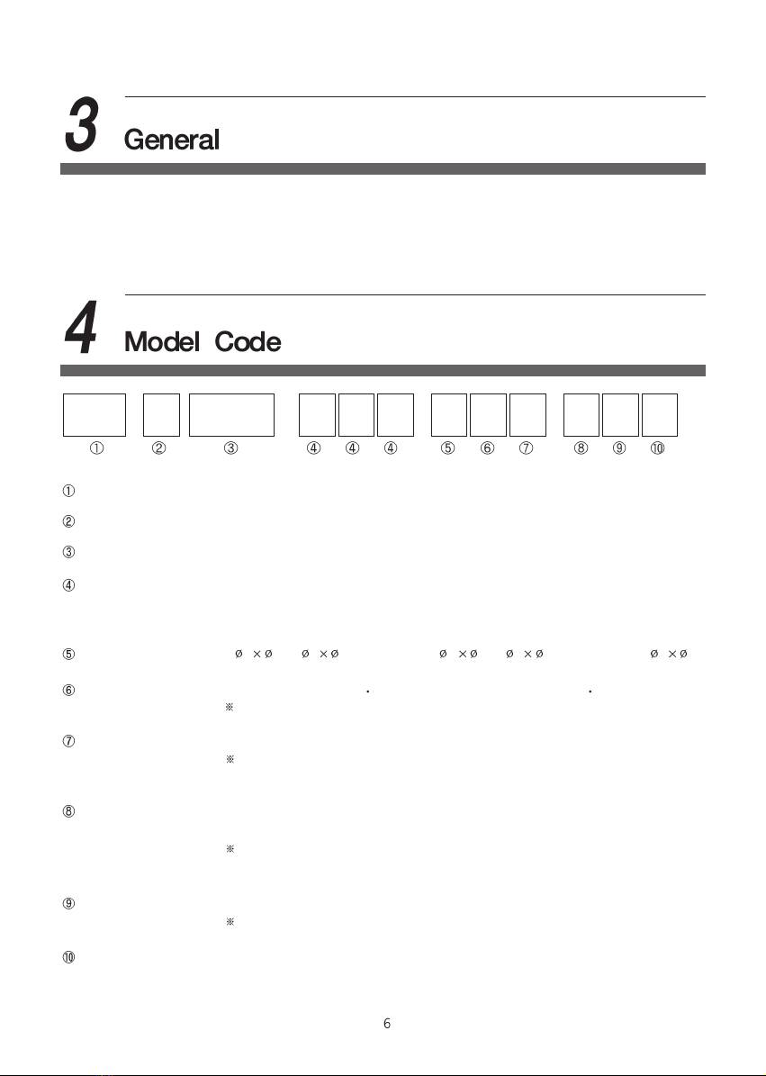
-a -b -c
011S
W
1CFP20ASP
Series Name SP: SP Series
Control Panel Type A: Automatic or Advanced
Nominal Capacity 20 : 20 mL/min
Liquid End Material (a) Head P:PP F:PVDF
(b) Ball Seat F:FKM E:EPDM V:FKM(ETP)
(c) Check Ball C:CERAMIC S:SS316
Hose Standard
1: 46 2: 49(Braided PVC) 3: 68 4: 611(Braided PVC) 5: 58
Valve Structure W:Standard(0~100mPa s) V:High Viscosity(100~1000mPa s)
In case of high viscosity, spring is installed in the valve.
General Specification S:Standard B:Boiler F:Relief Valve G:Boiler + Relief Valve
In case of Boiler type, discharge hose is nylon and the body of Anti-siphon
Check Valve is PPS.
Control Specification 1:Manual 2:Manual +Add. Func. 3:PULSE(1:1) 4:PULSE(1:1)+Add. Func.
5:4~20mA 6:4~20mA+Add. Func. 7:PULSE(DIV/MUL)+4~20mA+Add. Func.
Additional Function is Input of Level Switch, Output of Alarm, & Remote
RUN/STOP.
Power Supply 1:AC220V(198~242V) 2:AC240V(216~264V) 3:AC115V(104~127V)
Common:1 Phase 50/60Hz
Power Cord 0:2m of Power Cord without Plug 1:2m of Power Cord & Plug
Solenoid Metering Pump SP-A Series is reciprocating diaphragm metering pump which have a solid &
compact structure and liquid end part of strong chemical resistance.
It can be used for injection of Boiler Chemical, Chlorine Disinfectants, & Food Additives, and used for dosing
chemicals in various industrial fields including physico-chemical fields, semiconductor device, water
treatment, waste water treatment filed, & etc.
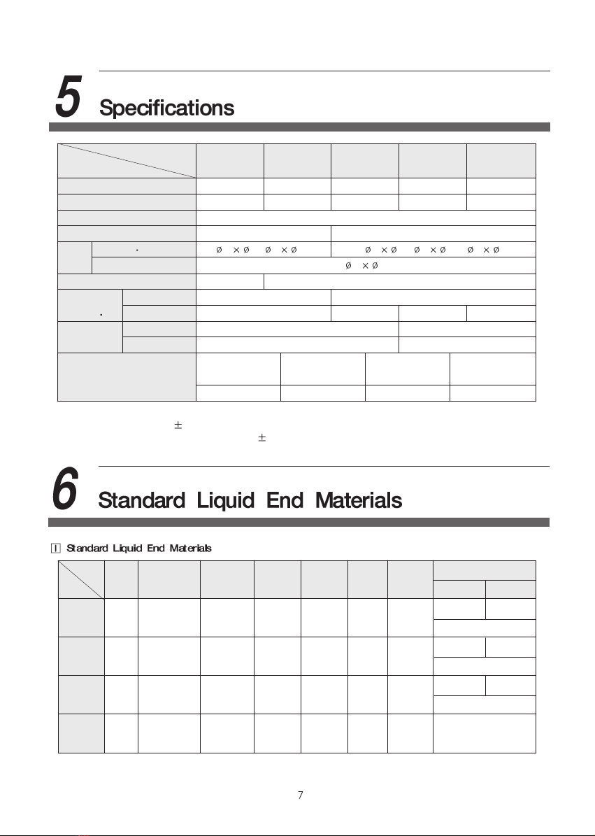
Model
Spec. SP-A20 SP-A40 SP-A60 SP-A100 SP-A200
Max. Capacity (mL/min) 17 35 60 110 200
Max. Discharge Pressure (bar)
16 12 8 5 3
Stroke Number (SPM) 150
Stroke Length (mm) 1.0 (40~100%) 1.25 (30~100%)
Hose Suction Discharge 46, 4 9 6 8, 611, 5 8
Air Vent 4 6
Self-priming (m) 1.5 2
Viscosity Limit
Standard 50 100
(mPa s) High Viscosity 500 1000 800 500
Weight (kg) PP Material 2.4 2.5
PVDF Material 2.5 2.6
Average Power Rated Current(A) Protection Class Insulation Class
Electrical Data Consumption(W)
17 0.5/0.8(115V) IP65 F
Note) 1. Max. capacity is the volume at max. discharge pressure.
2. Repeatability is 2%F.S.(Full Scale) and noise is within 70dB.
3. Setting pressure of Relief Valve is 10% of max. discharge pressure.
4. Specification can be changed for improvement without prior notice.
Note) In case of Boiler type, discharge hose is nylon.
Head Diaphragm
Check Ball
Ball Seat
Ball Guide
Joint O-ring
PFC PP PTFE
CERAMIC
FKM PP PP FKM
PFS PP PTFE SS316 FKM PP PP FKM
PEC PP PTFE
CERAMIC
EPDM PP PP EPDM
FVC PVDF PTFE
CERAMIC
FKM(ETP)
PVDF PVDF
FKM(ETP)
PTFE
Part
Type
Hose
Discharge
Suction
PE PVC
Braided PVC
PE PVC
Braided PVC
PE PVC
Braided PVC

Part Body Joint Check Ball Ball Seat Ball Guide O-ring
Type
PFC,PFS PP PP CERAMIC FKM PP FKM
PEC PP PP CERAMIC EPDM PP EPDM
FVC PVDF PVDF CERAMIC FKM(ETP) PVDF FKM(ETP)
Part Body Joint Plug Head Spring O-ring
Type
PFC,PFS PP PP FKM HC-276 FKM
PEC PP PP EPDM HC-276 EPDM
FVC PVDF PVDF FKM(ETP) HC-276 FKM(ETP)
Boiler PPS PPS EPDM HC-276 EPDM
Condition : Clean water, Room temperature, Suction head - 1m
Stroke Length(%)
Capacity Rate(mL/min)
020 40
25
60 80 100
5
10
15
20
Correction Factor
Pressure (bar)
0.8
1.0
1.2
1.4
1.6
1.8
161412108642
0
150spm
120spm
90spm
60spm
30spm
020 40
50
60 80 10
0
20
30
40
0.8
1.0
1.2
1.4
1.6
1
2
10.57.5630
150spm
120spm
90spm
60spm
30spm
10
94.51.5
45
35
25
15
5
Stroke Length(%)
Capacity Rate(mL/min)Correction Factor
Pressure (bar)

Note) 1. Above performance curves were tested
at our testing equipment under the
fixed condition(Clean water, Room
temperature, Suction head - 1m).
Therefore, performance curves can be
somewhat different in accordance with
condition of job site.
2. Way to understand performance curves
Ex.) In case of SP-A200,
Capacity Rate is 150mL/min at 80% of
Stroke Length & 120SPM of Stroke
Number. If discharge pressure is 1bar,
correction factor will be 1.1 and
expected capacity rate will be 165mL/min
(1.1 150mL/min = 165mL/min)
3. Capacity rate can be changed according to
piping condition of suction & discharge. For
effective use, measure the discharge
rate(make out performance curve) when trial
operation, after installation.
4. if test of capacity rate is regularly operated,
operator can know exchange cycle for the
consumable parts in Liquid End part.
Stroke Length(%)
Capacity Rate(mL/min)Correction Factor
Pressure (bar)
Stroke Length(%)
Capacity Rate(mL/min)Correction Factor
Pressure (bar)
020 40 60 80 10
0
0.8
0.9
1.0
1.1
0
150spm
120spm
90spm
60spm
30spm
3
250
1.51
1.2
225
200
175
150
125
100
75
50
25
2 2.5
Stroke Length(%)
Capacity Rate(mL/min)Correction Factor
Pressure (bar)

If electric power is supplied to the Solenoid Coil, magnetic field is generated in the Solenoid and Plunger
moves forward by magnetic force, and, if electric power is shout down, magnetic field disappears in the
Solenoid and Plunger moves backward by spring force.
Reciprocating motion of Solenoid Plunger is transferred to the Diaphragm connected with the end of
Slider Shaft and Diaphragm can be reciprocated. Volumetric change occurs in the pump head by this
reciprocating motor of Diaphragm.
When diaphragm moves backward, minus(-) pressure is generated in pump head. At this time, check ball
of discharge side is closed in order to prevent flowing backward of liquid from piping of discharge side to
pump head. On the contrary, check ball of suction side is opened so that liquid can be flowed into the
pump head.
When diaphragm moves forward, plus(+) pressure is generated in pump head. At this time check ball of
suction side is closed and check ball of discharge side is opened so that liquid can be discharged.
Capacity rate can be accurately controlled by adjustment of stroke length or stroke number.
The pump consists of Liquid End Part, Driving Part, Control Part as follows.
Liquid End Part Driving Part Control Part
1 Head 9 Pump Housing 13 Stroke Shaft
2 Diaphragm 10 Solenoid Coil 14 Circuit Board
3
Check Valve of suction side
11 Solenoid Plunger 15 Control Panel
4
Check Valve of discharge side
12 Spring 16
Control Knob for Stroke Length
5 Joint 17
Control Knob for Stroke Number
6 Air Vent 18 Cable Socket
7 Hose Nut
8 Support Ring
9
4
2
1
3
7
5
7
6
12 11
1
6
1
7
1
8
810 13 14 15
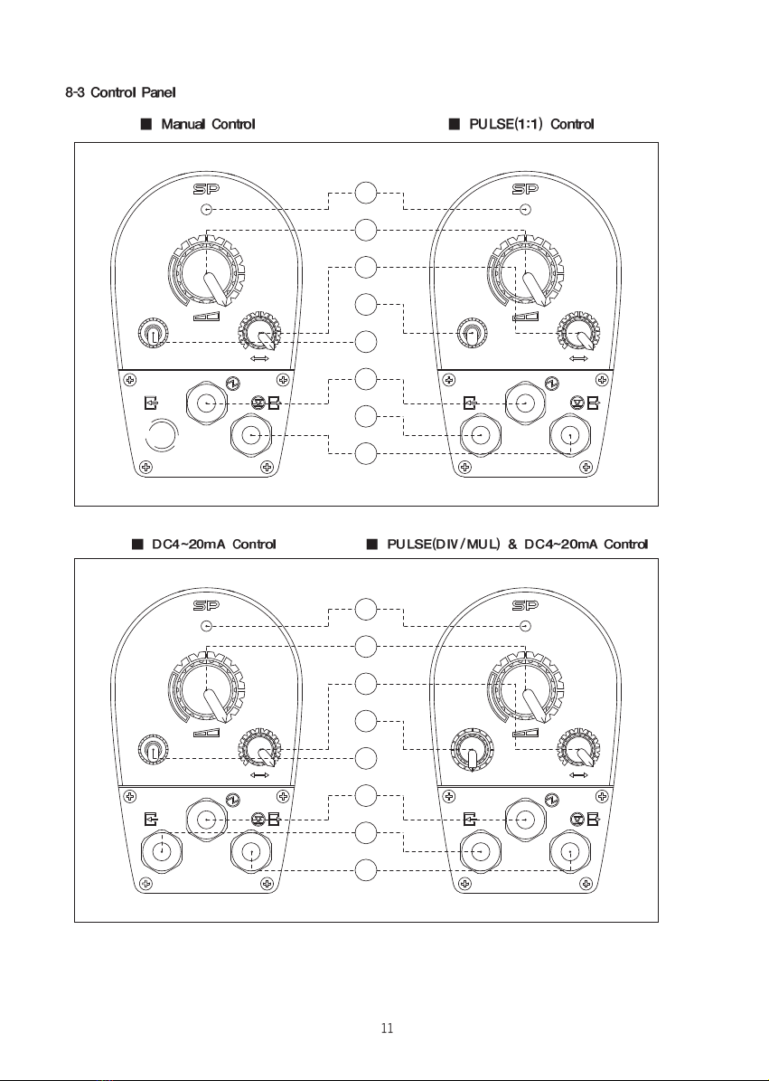
1: Status Lamp(LED) 2: Control Knob for Stroke Length 3: Control Knob for Stroke Number
4: Toggle Switch of 2 Stages 5: Toggle Switch of 3 Stages 6: Rotary Switch
7: Cable Socket for Power 8: Cable Socket for Input Signal 9: Cable Socket for Level Switch &
Output Signal
70
30
0
10
20 80
100
90
Solenoid metering Pumps
50
0
40
30
80
90
40
100
50 60
70
60
STOP
RUN
100
10
20
0
90
0
100
60
40 50
30
80
70
30
40 60
50
70
90
80
Solenoid metering Pumps
MANU
STOP
PULSE
1
2
3
4
7
9
8
5
Solenoid metering Pumps
70
30
40 50 60
80
90
100
0
1
STOP
/4
MANU
/64
/8
/32
/16
/2 X4
4~20mA
X8
X16
X32
X64
X2 30
0
10
20 80
100
70
90
50
40 60
MANU
STOP
0
90
10 0
100
30 40
20
100
70
80
50 60
Solenoid metering Pumps
30
40 50
70
80
90
60
4~20mA
9
8
7
5
6
3
2
1

Status Lamp(LED)
Stand by : Green Lamp is lighted
Operation : Green Lamp is flickered
Faulty Input Signal of DC 4~20mA : Yellow Lamp is lighted and Pump is stopped
Low level of Tank : Red Lamp is lighted and Pump is stopped
Operation by manual control according to Stroke Length and Stroke Number
Operation by automatic control according to external Input Signal
Proportionally Automatic control of Stroke Number according to Analog Input Signal(DC4~20mA)
PULSE : 1/2, 1/4, 1/8, 1/16, 1/32, 1/64 Division selection
1:1 selection
12, 1 4, 1 8, 1 16, 1 32, 1 64 Multiplication selection
Pump perform the calculated stroke number(SPM) according to the selection
Ex.1) When Rotary Switch is located at "1/4"
PULSE
PUMP STROKE
Ex.2) When Toggle Switch of 3 Stages is located at "PULSE" or Rotary Switch is located at "1"
PULSE
PUMP STROKE
Ex.3) When Rotary switch is located at "x4"
PULSE
PUMP STROKE
Note) Even if a lot of PULSE is inputted, pump's Stroke Number can't exceed 150SPM.
When Tank is LOW Level according to Input Signal of Level Switch or Analog Input Signal is ERROR,
Pump is stopped and Alarm Signal is outputted.
Pump can be remotely stopped or operated during Manual operation or Automatic operation by Input
Signal.
42
0
16.813.610.47.2
0
20
40
60
80
100
Stroke Number(%)
Analog Signal(mA)
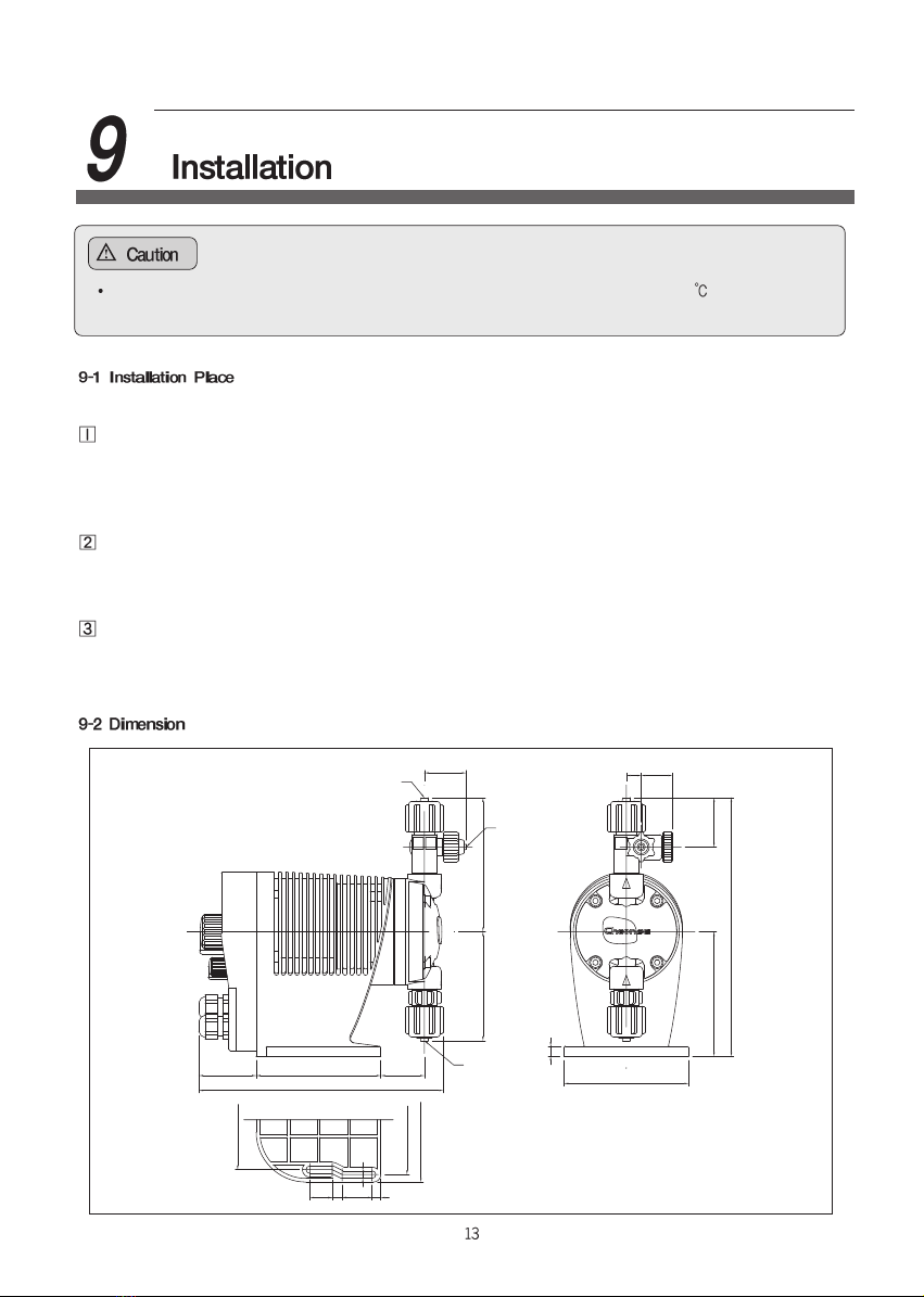
Please take into consideration of those conditions listed below.
Place where is out of the direct rays of light, rain, & wind.
Temperature rise of metal part, Heat deterioration of plastic part by direct rays of light and Damage &
rust by sand, dust and rain may occur.
If the pump should be installed at outdoor, the pump should be protected by roof or cover in order to
prolong the life time.
Place where is well ventilated in summer and not frozen in winter.
If pump is used in the closed room where is high temperature & humidity, solenoid will be overheated
and rust of metal part will be accelerated.
If pump is used for the liquid which may freeze in winter, install warming or heating device.
Take sufficient space around the pump to facilitate maintenance or repair.
Several tools are used for disassembly of pump, therefore, fully consider enough space for using tools
and work space when installing pump.
Do not install pump at the place where ambient temperature is higher than 40 or lower than
freezing point. If the pump is installed at the place, internals of the pump may be damaged.
12
100
100
8
E
C10046 D
B A
39.5
33.5
25
F
F
G
100
88
80
7
24
8
18
6

Pulsation which is the characteristic of metering pump occurs since the pump is reciprocating type.
Can reduce pulsation by using Air Chamber.
Note) Possible piping length is changed according to Liquid Viscosity or piping diameter.
When changing piping diameter, be fully careful.
When bending the hose, be careful not to be folded.
Before inserting Hose to Hose Adaptor, insert Hose
Nut & Clamp Ring, then be careful that Hose is not
twisted, and connect Joint & Hose Nut.
Hose is vibrated because reciprocating metering
pump makes pulsation.
Support Hose in order not to be vibrated.
(It is enough to support hose with string)
Install Hose in consideration of temperature condition.
Specially, keep out of the direct rays of light in summer,
consider freeze protection in winter.
(Roof, cover, winterization, & etc.)
When re-connecting Hose after maintenance,
re-connect after cut the end of Hose about min. 10mm.
Anti-siphon Check Valve
In case that injection port is open to atmosphere and its location is lower than liquid level in the tank.
Siphon Phenomenon: although pump is stopped, liquid may continuously flow because location of
discharge port is lower than liquid level in suction tank
If there is constant pressure at injection port, it may be used as Check Valve.
When injecting to suction piping of centrifugal pump
When flow is much larger than rated capacity
(In spite of upward piping, if piping length is too long, Overfeeding can be generated.)
Overfeeding : Overfeeding stands for the excessive discharge flow due to abnormal function of the
Check Valve caused by pulsation of the liquid in piping.
Check carefully differential pressure if the differential pressure between suction side and
discharge side is lower than 0.5~1 bar and discharge piping is too long.
Model SP-A20 SP-A40 SP-A60 SP-A100 SP-A200
Dimension
A 96.5 99 101 102.5 107.5
B 76.5 79 81 82.5 87.5
C 33.5 33.5 33.5 35 35
D 194.5 194.5 194.5 196 196
E 196.5 199 201 202.5 207.5
F 4 6, 4 9 6 8, 611, 58
G 46
Hose Nut
Hose
Clamp Ring
Hose Adaptor
O-ring
Joint
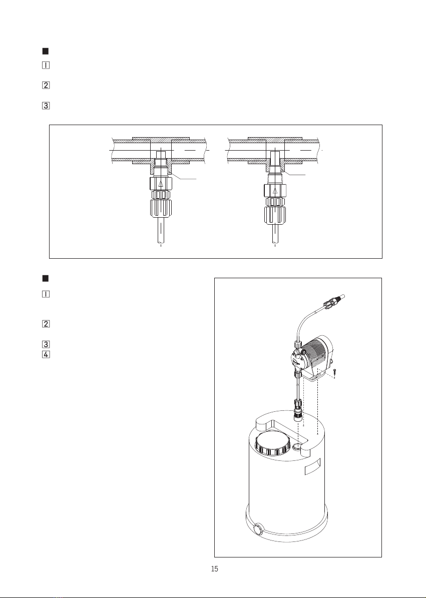
Mounting of Anti-siphon Check Valve
Install Rc3/8 or Rc1/2 of Female Thread at the injection point.
Fits both sizes because Anti-siphon Check Valve has both R3/8 and R1/2 of Male Thread.
Anti-siphon Check Valve is fragile against impacts since it is made by plastics such as PP, PVDF, &
PPS, therefore, install it in a place sheltered from impacts and free from obstacles.
Cut off the end of the injection nozzle properly. It is suitable that the end of injection nozzle is
positioned in the middle of water pipe.
Installation on Liquid Tank
Fix the pump to the bracket on the tank, by
using the Mounting Bolts supplied as
standard accessories.
Pass the Hose Nut into the suction side
hose and connect it to the Strainer Foot Valve.
Place the Strainer Foot Valve into the tank.
Pass the Hose Nut into the discharge side
hose and connect it to discharge side Joint of
pump.
Drive the Anti-siphon Check Valve into the
injection point and connect the hose.
R
R1/2 R3/8
Solenoid Metering Pump
Anti-siphon Check Valve
Mounting Bolt
Strainer Foot Valve
Liquid Tank
Do not touch with wetted hand. Electric shock may be occurred.
Before wiring, check voltage, phase, & frequency and connect the pump with correct power.
It may cause trouble and fire, if connecting with incorrect power.
Pump should be properly grounded in order to prevent electric shock.
Entrust the wiring to electrical engineer.
Install regulated Magnet Switch and Thermal Relay for the adjustment and maintenance of the pump.
Use standardized parts in wiring and fully pay attention to safety in accordance with the technical
standard & wiring regulation of the electrical equipment.
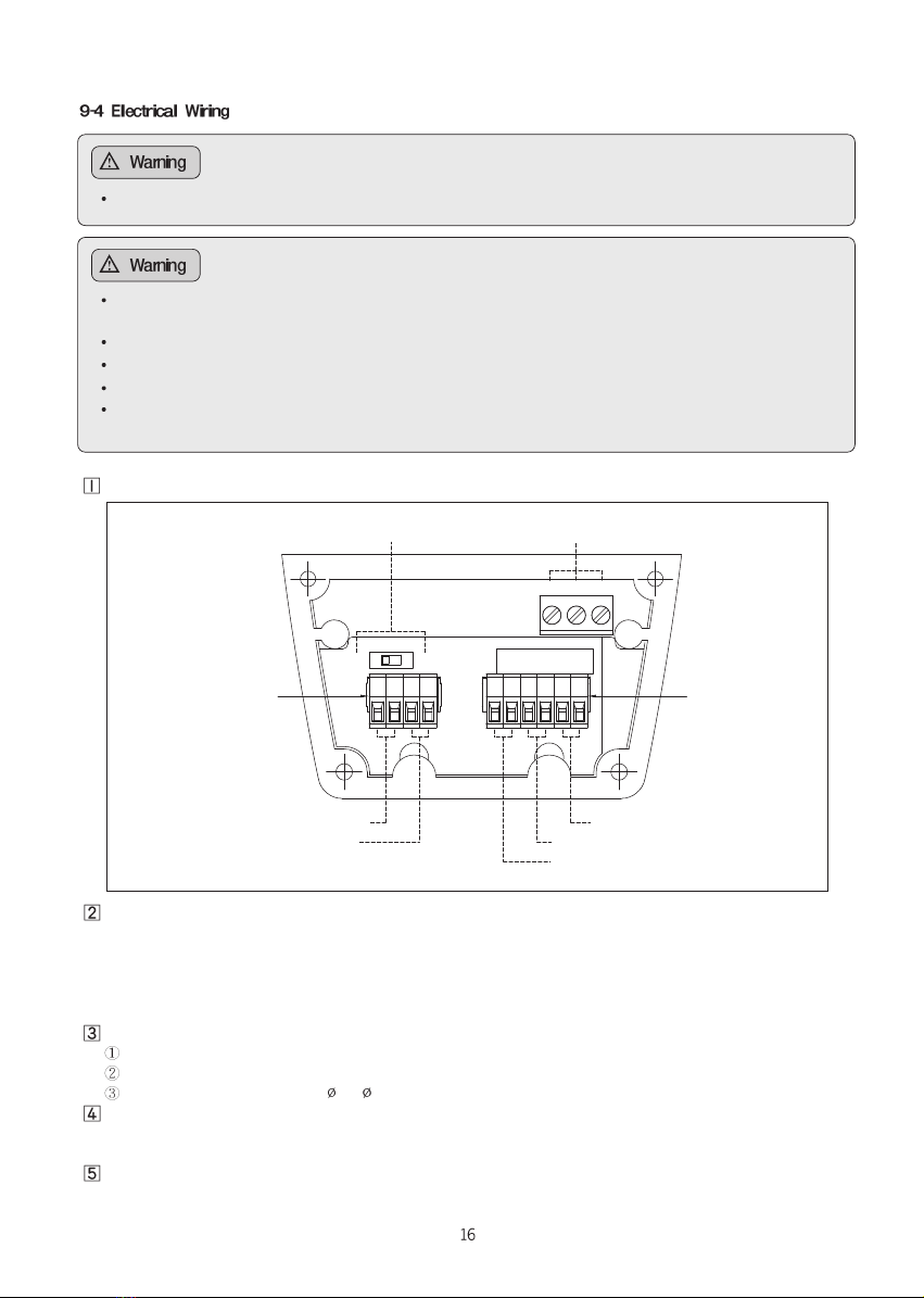
Disassemble Terminal Cover after loosening tapping screw from Control Panel by (+) screwdriver.
Connector inserted to Terminal Block
Separate the Terminal Connector connected to Terminal Block by Long Nose Plier and after passing the
wire into the Cable Socket and inserting the wire to the Terminal Connector.
Fix it by (-) screwdriver.
Terminal Block for external contacts such as Level Switch is connected with jumper wire.
Before wiring, remove it.
Allowable wire standard for Terminal Block & Cable Socket is as follows.
Terminal Block for Flow Control & Additional Function : AWG16~30
Terminal Block for Power : AWG18~26
Cable Socket: External dia. 4~ 8
Put the Terminal Connector connected with wire into the Socket of Terminal Block and assemble the
Terminal Cover.
Tighten the Cable Socket so that wire don't be fall out, after adjusting wire length.
Power wires are 3 wires including ground. be careful not to confuse since Green & Yellow color are
used for ground wire.
DI1 DI2
A+A-P+P- L1 L2 R1 R2 A1 A2
AC-L AC-N F.G
Power Cable
Alarm Output4~20mA Input
RUN/STOP Input
PULSE Input
Level Switch Input
Selection Switch for PULSE
Terminal Block
Function for Flow Control Terminal Block
Additional Function
Terminal Cover
Power Terminal Block
Terminal Connector
Terminal Socket
Cable Socket
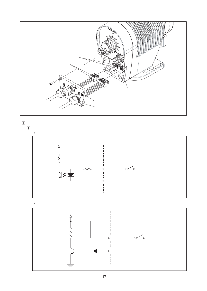
Diagram of Electric Circuit (Example)
PULSE Input Signal: Min. PULSE Duration Time is 4ms
DI1 Selection: VOLTAGE WITH OPEN CONTACT
DI2 Selection: NO VOLTAGE WITH OPEN CONTACT
PUMP USER
R
P+
PULSE
VDC
NPN
D
P -
PUMP USER
OPTO-COUPLER
R
R
P+
PULSE
DC12~24V
VDC
1
2
34
P -
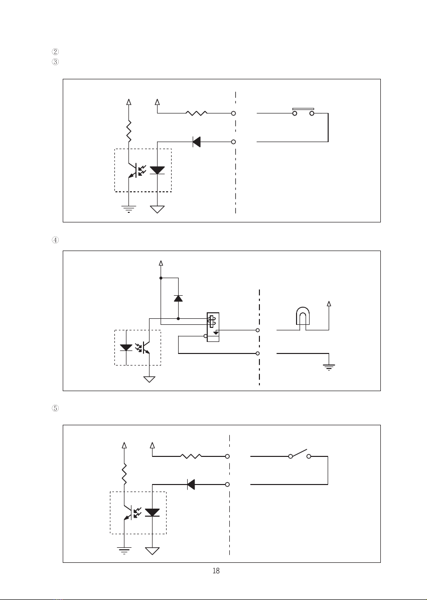
DC4~20mA Input Signal
LEVEL SWITCH Input Signal : NO VOLTAGE WITH OPEN CONTACT
OPEN : LOW LEVEL CLOSE: NORMAL LEVEL
ALARM Output: DRY CONTACT (SPST) Contact Capacity: 3A 250VAC (5A 30VDC)
REMOTE RUN/STOP Input Signal : NO VOLTAGE WITH OPEN CONTACT
OPEN : PUMP STOP CLOSE: PUMP RUN
PUMP USER
34
12
OPTO-COUPLER
+12VVDC
D9
R
R
LEVEL SWITCH
L1
L2
USERP
34
12
3
4
1
2
OPTO-COUPLER
+12V
D
ALAM LAMP
POWER
A1
A2
RELAY SPST(NO)
UMP
PUMP USER
34
12
OPTO-COUPLER
+12VVDC
D9
R1
RUN SWITCH
R2
R

Do not operate when the discharge valve is closed or do not close the valve during operation.
Pump and piping may be damaged with excessive pressure rising and liquid may spout when operation
under valve closing.
Do not turn the Control Knob of Stroke Length & Stroke Number below 0% or over 100%.
When discharge valve of pump is clogged with foreign substance, pressure is raised and liquid is
spouted and it cause damage of piping.
Wear suitable protective clothing(gloves, mask, goggles, working clothes, & etc.) when pumping
hazardous liquids.
Some water may be remained in the pump after final performance test.
In case of use for some liquids reacted to water, remove water in the pump and dry the pump necessarily.
Check if suction side and discharge side hose is tightly connected, and Hose of Air Vent is connected with
Liquid Tank or other container.
Set each Control Knob to 100% and operate the pump after turning the Air Vent Cock counterclockwise
about 1~ 1 revolutions.
Confirm that liquid is flowed through Air Vent and start normal operation after closing the Air Vent Cock by
turning it clockwise.
In case of the pump attaching Relief Valve, if the Knob of Relief Valve is clockwise turned about 90°, Air
Vent Valve is opened. On the other hand, if the Knob of Relief Valve is clockwise turned about 90° again,
Air Vent Valve is automatically closed by spring force.
Since capacity Rate is controlled by both the Control Knob of Stroke Length and the Control Knob of Stroke
Number, fine control of capacity rate is possible.
Tan k
Discharge Piping
Relief Valve
Air Vent Cock
Knob(Relief)

Turn off the power and stop pump & other equipments before repair & maintenance, otherwise it may
cause electric shock.
Wear suitable protective clothing during assemble and disassemble work.
Work after releasing pressure from discharge piping and remove liquid from Liquid End Part prior to
repair or maintenance of pump..
Check the level of liquid tank and, if it is insufficient, supplement the liquid.
Check if the valves on the suction & discharge piping are opened.
Check if piping is loosened or damaged.
Check electrical wiring if there are no electrical short & disconnection.
Check the level of liquid tank and, if it is insufficient, supplement the liquid. Specially, be areful for the
process or chemical influenced by Air.
Check if liquid is leaked out the Joint or other parts. If necessary, fasten it again.
If leakage doesn’t stop, check O-ring and/or Packing of each parts and replace the damaged O-ring
and/or Packing with new one.
Check if noise sounds from the pump.
Check if the needle of pressure gauge is located at normal range.
Wash inside Pump Head by drawing & discharging clean water for 30 minutes.
Put the cover on the pump to protect it from dust and/or corrosion.
Set the Control Knob of Stroke Length at 100% in order to prevent the deformation of diaphragm.
Check foreign substances lay on the Check Ball and/or Ball Seat before restarting the pump.
When diluted liquid or high viscosity liquid is used at freezing place in the winter, install HEAT TRACING
to prevent the pump from freezing because it causes the damage of the pump & other devices with
freezing on the liquid end part of pump and inside piping.
Clean the inside of Tank and Joint every 3 months at least.
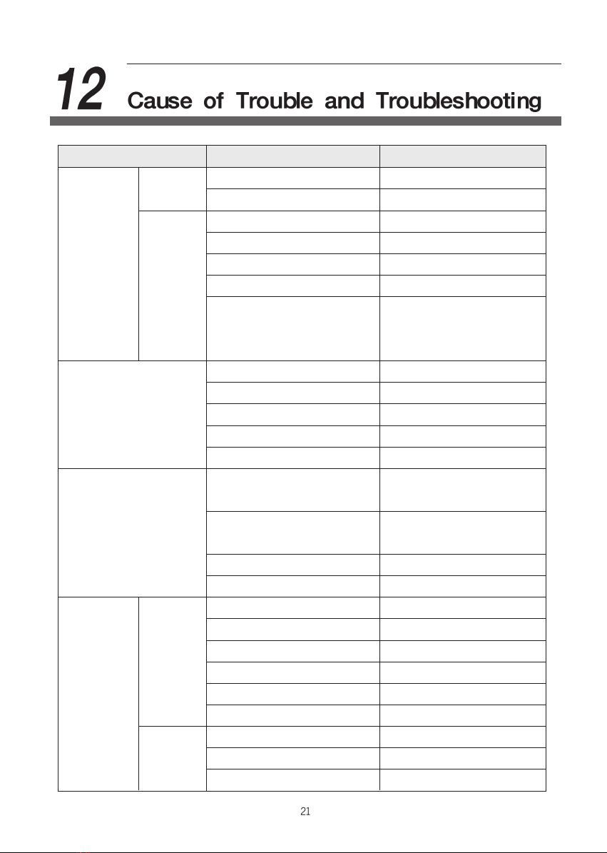
Trouble Cause Troubleshooting
Leaks from joint or sealing part Check o-ring & tighten
Empty tank Fill up and expel air
Strainer is clogged Clean strainer & tank
Pump head is filled with gas Purge the gas by air vent cock
Assembly direction of valve is wrong Re-assemble the valve
Ball Seat is worn out Replace
Set stroke length at 100% and
Short stroke length control discharge capacity by
stroke number
Check ball & ball seat are damaged Replace
Spring is broken Replace
Diaphragm is aged or broken Replace
Setting of knob is wrong Readjust
Liquid being treated is changed Recheck the pump specifications
Pressure is increased by foreign Disassemble and clean
substance or clogging
Hose or diaphragm broken due Replace
to fatigue
Head and joint are loosened Tighten
There is no o-ring Insert o-ring
Wrong voltage Check voltage & correct
Wrong wiring Check the wiring & correct
Disconnection of cable Modify or replace
Switch is cut off Turn on switch
Fuse is burnt out Check the cause and replace fuse
Defective magnetic switch Replace
Unsuitable voltage Connect suitable voltage
Spring is broken Replace
Defective solenoid Check the resistance & insulation
Pump is
running but
liquid is not
discharged.
Air is drawn
Suction is
not
sufficient.
Insufficient discharge rate
Leakage of liquid
Pump dose
not run
Status
Lamp(LED)
is off
Solenoid
does not run
Other Cheonsei Water Pump manuals


Popular Water Pump manuals by other brands

Xylem
Xylem GOULDS NPO instruction manual

Teral
Teral LPWE-GS instruction manual

Grundfos
Grundfos Hydro Multi-B instructions

Zwilling
Zwilling Fresh & Save Vacuum Storage System operating instructions

T.I.P.
T.I.P. GP 4500 INOX operating instructions

Markes International
Markes International ACTI-VOC Operator's manual


