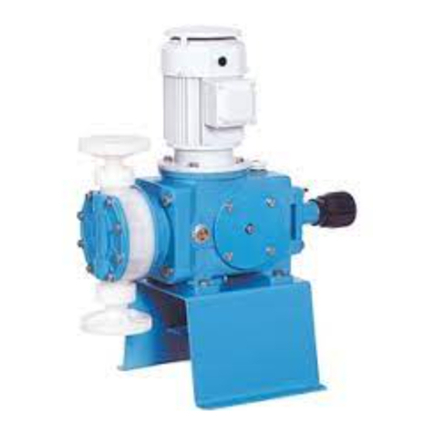
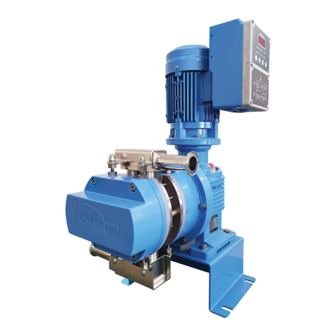
Cheonsei Kempion PKD Series User manual

PKD TYPE
Pulseless Diaphragm Pump
Instruction Manual
www.cheonsei.co.kr
ISO 9001
METERING PUMPS

2
Thank you for purchasing our PKD pump.
Read this manual before using the product. Handling and maintenance are
explained in easy way. Read through this manual and use the product safely to
assure pump performance and long service life. Please keep this instruction
manual at the place where you can see it easily.
1. Cautions for safety …………………………………………………………………3
2. Product confirmation 4
3. Overview ……………………………………………………………………………4
4. Model Code …………………………………………………………………………5
5. Material of standard wet side ………………………………………………………6
6. Specification & capacity table………………………………………………………6
7. Performance curve …………………………………………………………………7
8. Operation principle and structure …………………………………………………8
9. Installation ………………………………………………………………………… 10
10. Operation ………………………………………………………………………… 12
11. Maintenance & inspection ……………………………………………………… 14
12. Cause and measure of trouble………………………………………………… 16
13. Replacement of Parts ………………………………………………………… 17
14. Consumable Parts and Spare Parts ………………………………………… 20
15. Warranty ………………………………………………………………………… 21
16. Repair service …………………………………………………………………… 21
17. Accessories ……………………………………………………………………… 21
18.
Structure and Name of Each Parts
………………………………………… 22
CONTENTS

3
1-1
Instruction
•Instruction
Manual is described as below to use the product safely.
•
Always follow the manual because it is very important for safety.
•
Each symbol and its meaning are described as below.
Regarding the BLDC M/C UNIT supplied by us, always follow all directions (i.e., warning, caution
etc.) described in the
instruction
manual specially provided as well as warnings and cautions in this
manual.
Warning
Death or serious injury may occur if handling the product in a wrong way without following a warning.
Caution
Injury or property damage may occur if handling the product in a wrong way without following a caution.
1-2 Caution for operation conditions
Caution
•Do not use this pump except for injecting liquid. It may cause an accident.
•Follow below condition; otherwise, it may cause trouble:
Ambient temperature: 0 ~ 40℃
Pipe pressure: Less than the maximum discharge pressure indicated in the specification/ capacity chart
※ Pressure over the allowable one may cause damage to the product, so install safety valves(i.e relief
valve) and strainers at pipes.
1-3
Caution for handling
Warning
•Install this pump beyond the reach of children and/or unauthorized person
•Turn off the power and stop the pump & other equipments when repairing or disassembling
pumps. If power is on during work, it may cause electric shock
•Please do not operate when the discharge valve is closed or do not close the valve
during operation. Pump and Piping may be damaged with excessive pressure rising and
liquid may spout when operation under valve closing.
• Be careful not to insert ngers or any foreign substances into rotating or reciprocating objects
during operating pump. If you touch it during operation, you may get injury.
•Do not touch with wet hands. Electric shock may occur.
•Use only designated parts. If undesignated parts are used to the pump, it may cause
accident & trouble.
•Do not arbitrarily reconstruct the pump. If the pump is arbitrarily reconstructed, it may
cause accident & trouble.
1
Cautions for safety

4
2-1 Checklist after unpacking
Please check following points immediately after receiving the pump.
If the defect is found from pump, please request it to local agent or CHEONSEI.
Are the products the same as you ordered?
Is there any missing parts ?
Is there any visible damage caused by vibration or shock during transport?
Is there any loosened bolt or nut?
2-2 Standard Accessories
Instruction manual …………………………………………… 1 copy
Installation bolts ……………………………………………… 4 sets
PKD series are a pulseless diaphragm metering pump which pulse rate of discharge capacity is reduced.
Chemical is sucked and discharged by reciprocating diaphragm which is attached to Slider Shaft by
Constant Velocity Cam after reducing the rotation of motor by Worm Gear. PKD series have double head. In
case of BLDC M/C UNIT installed, stable capacity is maintained in low-speed, and feedback is quick.
Caution
• Do not use damaged pump. It may cause accident.
• Do not install pump in the heavy moist or dusty place. It may cause electric shock and trouble.
• Do not touch motor with bare hands during operation. High temperatures can cause burns.
•Wear suitable protective clothing(gloves, mask, goggles, working clothes, & etc.) during
assemble and disassemble work when pumping hazardous liquids or uncertain liquids.
• Do not use power other than that specied in the motor nameplate. Otherwise, it may cause
malfunction or re.
•Pump should be properly grounded. If pump is not grounded, it may cause electric shock.
•Work after releasing pressure from discharge piping and remove liquid from Liquid End Part
prior to repair or maintenance of pump.
•Pump may be damaged when ambient temperature go down below freezing pont of liquid. Be
sure to remove the liquid in the pump and piping after operation stop.
•Make proper protection in consideration of indeliberate leakage from damage of
pump & Piping.
•Dispose of waste pump in accordance with related national law.
1-4
Noise
- Maximum measured A-weighted emission sound Pressure level(LpA) : 72.0dB(A)
2
Product Comfirmation
3
Overview

5
P
K D
-
2 1 2
-
S T S
-
F W S
-
1 2
-a
-b
-c
-a
-b
-c
ⒶBrandname PULSELESS MERTRING KEMPION
Ⓑ
Type of wet side (classification by pump structure)
D : Diaphragm type(P : Plunger type)
Ⓒ
Discharge amount
ⒹLiquidEnd
Material
a :
Material code of head
P : PVC F : TEFLON S : STS304 6 : STS316
b :
Diaphragm material code
T : PTFE E : EPDM
c :
Check ball material code
C : CERAMIC S : STS304 6 : STS316
Ⓔ
Connection type
F :
Flange connection
X :
Special
Ⓕ
Viscosity limit
W: Standard
X : High viscosity
Ⓖ
Power Supply
S : 3-phrase, 380~ 480V
A : 3-phrase, single phrase 200 ~ 230V
(1.5KW-grade available only for 3-phrase)
(2.0KW-grade available only for 3-phrase 380~480V)
X : Special order
Ⓗ
Junction pipe
1 : Attached 2 : Attached + Relife Valve
0 : Not attached
Ⓘ
Remote Control Method
1 : Inverter
2 : BLDC M/C Unit(Auto)
3 : BLDC M/C Unit(Manual)
0 : Not attached
4
Model Code

6
Specification PKD Series
-500 -121 -241 -521 -102 -212 -412 -702 -143 -113 -203 -243 -333 -423 -613 -813
Max. discharge amount(mL/min)
50 120 240 520
1040 2100 4100 7000
14900 11200 20700 24000 33000 42000 61000 81000
Max. discharge pressure(bar)
10 8537575333
Pulse rate(%) F/S
Stroke length(mm)
3 4 6 10 15 12.5 17.5 15 20
Max. stroke number(spm)
58 116 58 116 58 116 58 116 87
Transfer-available temperature(℃)
STS, 6T6, : 0~80℃ / PTC : 0~50℃ / Ambient temperature : 0~40℃
Connection(FLANGE)
KS 10K 15A KS 10K 25A KS 10K 40A
KS 10K 50A
Motor(BLDC)
0.55kw / FR71 0.75kw / FR80 1.5kw / FR90
2.0kw
Note) 1. Maximum discharge amount means the discharged amount under the discharge-allowed pressure, in the standard
state (room temperature, clean water).
2. The effective flow rate-controllable range is 20~100%. (Operation available within 10 ~ 100%)
3. To order special motor, such as explosion-proof motor, other than the standard motor specification, please contact
us separately.
4. The weight means that of STS wet side including the standard motor.
5. In case of PTC or FTC wet side, the temperature of liquid to be handled is 0~50℃; in case of STS or 6T6, it is 0~80℃.
6. The liquid where slurry or solids is mixed is not acceptable for pulseless and/or metering injection.
7. The self-priming is 1M, and the ambient temperature is 0~40℃.
8. For painting, Munsell No. 0.6PB 4.8/10.6 or similar colored corrosion painting is used. (The special motor has the
standard color specified by its manufacturer)
9. The pump specification and capacity may change without notice, for improvement.
5
Material of standard wet side
6
Specification & capacity table
PTC FTC STS(6T6)
Part name Type 500~102 212~813 500~203 243~813 500~102 212~203 243~813
①Head PP PVC PVDF
PVDF(PTFE)
SSC13(SSC14)
②Diaphragm PTFE(EPDM) PTFE PTFE
③Check ball CERAMIC(STS304) CERAMIC STS304(STS316)
④Ball guide PP PVC PVDF
PVDF(PTFE)
PVDF SSC13(SSC14)
⑤Ball seat
FKM(EPDM)
PVC PTFE(PVDF) PTFE
STS304(SSC14)
⑥Joint PP PVC PVDF STS304(STS316)
⑦O-ring·packing
FKM(EPDM)
FKM PTFE PTFE
⑧Junction pipe PVC PVDF STS304(STS316)
Note) If you want other than the above standard material, please contact us for special order. (* means
customized product)
Material code

7
● PKD-102 ● PKD-212
● PKD-412
● PKD-521
● PKD-113 ● PKD-203 ● PKD-243
● PKD-500 ● PKD-121 ● PKD-241
● PKD-702 ● PKD-143
Condition: Room temperature, clean water, suction - (1M)
7
Performance curve

8
8-1 Operation principle
Fig. A General metering pump(Single Head)
Diaphragm
Check Ball Slider
Sinusoidal wave by a eccentric cam
Instantaneous
Discharge
1 Rotation
Capacity
A discharge
A Suction
Eccentric cam
Fig. A General metering pump Sinusoidal wave by a eccentric cam
● PKD-613
60
50
020 40 60 80 100
10
20
30
40
3 bar
1 bar
70
● PKD-813
● PKD-333 ● PKD-423
8
Operation principle and structure
Note)
Above performance curves were tested at our testing
equipment under the fixed condition(Clean Water, Room
Temperature, & 1m of Suction Head).
Therefore, performance curves can be somewhat different in
accordance with condition of job site after installation.

9
<Figure A> shows the pulse wave by a eccentric cam for a general metering pump. The pulse of metering
pumps generates when the eccentric cam is used to convert the power of the motor into reciprocating
motions. This eccentric cam is a circular object with the eccentric amount of e, so the reciprocating velocity of
the diaphragm has sinusoidal wave. This is why the discharge flow rate has pulses.
Fig. B Pulseless metering pump(Single head)
Diaphragm
Check Ball
Slider
Niddle bearing
Velocity cam
Constant velocity wave by a constant velocity cam
1 Rotation
Capacity
discharge
Suction
Instantaneous
Discharge
Fig. B Pulseless metering pump constant velocity wave by a constant velocity cam
<Figure B> shows the pulse wave of a constant velocity cam, having a constant velocity section in the flow
rate. Because the constant velocity cam operates the diaphragm in a constant velocity, the discharge flow
rate is constant, too. The constant flow rate in this section is the pulseless flow rate. However, the
reciprocating metering pump always has a suction section if it has a discharge one, so in order to obtain
constant pulseless flow rate, two wet sides should be used to have constant discharge.
Fig. C Pulseless metering pump(Double head)
Implementation of pulseless line by using
a constant velocity cam and two wet sides
1 Rotation
Capacity
Discharge is constantly
kept because an interial
A and an interial B are
piled up.
A discharge B discharge
A
Suction
B
Suction
Instantaneous Discharge
Fig. C Pulseless metering pump implementation of pulseless line by using a constant
velocity cam and two wet sides

10
9-1 Installation Place
Keep the pump out of the direct rays of the sun, rain and/or wind.
Install the pump at a well ventilated place in summer and at a place where the transferred liquid is not
frozen in winter.
If possible, install the pump at a place which is lower than the minimum surface of liquid in the tank.
For easy maintenance and repair, secure enough surrounding space. Install the pump with
consideration of safety of motor and electric wiring in case of flooding.
Caution
• Do not install the pump at the place of which ambient temperature is higher than 40℃or lower than
the freezing point. The inside of the pump may be damaged.
• For stable operation, do not install it at a dusty and damp place.
•Do not apply external force to junction pipes of the pump. The pump may be deformed or damaged.
8-2
Inside structure
Motor
Velocity cam
Diaphragm
Check ball
Junction pipe
Slider
Niddle bearing
Worm shaft
9
Installation

11
The floor should be even, and the installation place should be free from vibration caused by other
machines.
Install the pump with props which can support the pump fully, while referring to the foundation drawing.
Use the level instrument so that the pump can be attached horizontally.
Pay attention not to have water or used liquid invade the BLDC motor during cleaning the pump. If
water invades, an electrical accident may occur due to fire or electric shock.
9-2 To Move the Pump
To move the pump, grab the wet side head and
bed firmly. Be careful for the junction pipe not to
have external force.
※Never grab the junction pipe by hand to move it.
(Especially, in case of PVC or PVDF material, the
junction pipe may be damaged.)
9-3 Pipe(General caution)
Decide the piping system which can
sufficiently satisfy suction & discharge
condition.
Piping should be short and less bending as
far as possible and be careful not to make
the cavity at which air stay.
Install piping support lest piping load fall on
the pump. Especially, in case of liquid end
material of PVC, be careful about handling.
Be careful that pump is not to be inuenced
with thermal stress of piping when
transferring hot liquid or cold liquid.
Don’t make U shaped bend in the piping
when transferring easily precipitable slurry.
Install a ushing pipe line for maintenance
and inspection when transferring viscous
liquid, poisonous liquid, or coagulative
liquid.
Choose the piping material that has
sufcient corrosion resistance to the liquid
and can endure the pressure applied in the
piping.
Connect piping after ushing the inside of
piping cleanly and remove the inspection
sticker for preventing entrance of foreign
substance on the discharge port.
Protect the piping with insulating material
or keeping warm device, if the liquid may
freeze inside of piping. In addition, Install
drain valve at the suction & discharge side
in order to drain the liquid inside piping
after operation stopped.

12
9-6 Electrical wirning
9-4 Suction Pipe
Suction piping is made with drop method as far as possible. Also, the diameter of the suction
piping should be larger than or same with the suction diameter of the pump.
Carefully connect the joint of suction piping in order to prevent air inow into the piping.
Discharge rate of pump can be destabilized by air Inow into the piping.
Make piping length of suction side as short as possible. If it is too long, cavitation occurs and
regular discharge rate can‘t be assured.
Install a strainer on the suction piping because it make unstable performance that foreign
substances ows into pump head.
9-5 Discharge Pipe
Use a discharge pipe of which internal pressure is higher than the set value of the safety valve.
If discharged at the pressure less than the atmospheric pressure, keep the pipe end higher than the
level of the tank, or install the back pressure valve to prevent siphon phenomenon.
(Please get consulation before installation of back pressure valve because pulse rate can be slightly
increased.)
Warning
•Do not touch the product with wet hands. You may get an electric shock.
Caution
•Before wiring, check voltage, phase, & frequency of BLDC M/C UNIT and connect the pump with
correct power. It may cause trouble and re, if connecting with incorrect power.
•Pump should be properly grounded in order to prevent electric shock.
•Entrust the wiring to electrical engineer.
•Install regulated Magnet Switch and Thermal Relay for the adjustment and maintenance of the pump.
•Use standardized parts in wiring and fully pay attention to safety in accordance with the technical
standard & wiring regulation of the electrical equipment.
10-1 Driving preparation
Caution
• When foreign substances are held in the discharge pipe of the pump, the pipe may be damaged due
to pressure increase and people can be hurt due to liquid burst-out, so always be careful for foreign
substances not to come into the pipe.
• To handle hazardous liquid, always wear the protective equipment (i.e., protective gloves, mask,
protective glasses, liquid-resistance working clothes etc.).
•
Some water may be remained in the liquid end part of pump after nal performance test. In case
of use for some liquids reacting radically to water, remove water in the pump and dry the pump
necessarily.
10
Operation

13
10-1 Driving preparation
Check if there is oil leakage caused
by any damaged parts or loosened
bolt. Excessive leakage of working
oil may affect the discharge volume.
Check the oil gauge to see if the
driving part of pump is lled with the
oil of regulated amount.
The normal position of the oil level is
the middle red point of the gauge.
Remove the black pin of the oil
cap. This is attached to prevent oil
leakage during delivery.
Check if all of accessories, liquid to
be transferred, and power supply
necessary for pump operation are
ready.
10-2 Driving
Open the suction and discharge valves.
Check the rated power and turn on the pump. Check if the motor fan rotates clockwise. (When the inverter
or general motor is used)
Open the discharge side up to the atmospheric pressure, and increase the discharge amount slowly up to
50%. Check if the transferred liquid reaches the junction pipe. Connect to the flange of the discharge side.
And than, operate test run for 30minutes.
Caution) When the ambient temperature is low, overload may occur temporarily due to low temperature of
lubricant. Wait until the lubricant temperature increases with no load.
If there is no error found during test run, increase the pressure of the discharge side up to the setting one.
Check if the BLDC controller works properly or if every part works properly.
10-3
Control of discharge amount
The discharge amount can be controlled by the controller (BLDC M/C UNIT).
The controller can operate within 10 ~ 100%, but its effective flow rate-controllable range is 20 ~ 100%.
(Within 20 ~ 100%, the discharge amount is stable)
10-4 Restart of pump
In case of stop pump operation for short period(less than 1 week), run the pump at a desired stroke length &
prescribed discharge pressure after air bleed operation.
In case of stop pump operation for a long period(more than 1 week), the pump should be run at atmospheric
pressure of discharge side for several minutes before going into normal operation. Do not start regular
operation before above warming up.(Set the controller to 50%)
It is concern that pump is damaged by freezing during winter season. Without regard to stop perioed of
operation, drain the liquids in the piping and pump by operating dry run after opening the drain valve on the
suction piping.
Warning
•Do not use the controller (BLDC M/C UNIT) below 10%.
PKD-521,102
BLDC M/C UNIT
Oil level cap
Oil cap
Junction pipe(Top)
Head
OIL
Junction pipe(Bottom)

14
11-1 Inspection before operation
Check the level of liquid tank and, if it is insufcient, supplement the liquid.
Check if the suction & discharge valve are opened.
Check if piping is safe and undamaged.
Check electrical wiring if there are no electrical short & disconnection.
Caution
•
Wear suitable protective clothing during assembly and disassembly work.
•Work after releasing pressure from discharge piping and remove liquid from Liquid End Part
prior to repair or maintenance of pump.
10-5
Confirmation of discharge amount
If pump has no problem, check the discharge volume under actual running condition with
measuring device such as mass cylinder.
If discharge volume had no uctuation after repeated measurements, the pump is judged to be
running normally.
When the discharge amount increases/decreases by changing the motor speed, measure the discharge
amount one minute or more after the change.
Note) If you request the test report, we submit the test report which has been performed at normal temperature
and with clean water. The result may vary depending on on-site pipes and transferred liquid.
10-6
Pulse rate increase
The pulse of the metering pump largely depends on pipes and transferred liquid.
(Since the factory test condition is not same as your on-site condition, the result may be different.)
Besides, if the pump operates after a long stop, its metering performance and pulse rate may change due to
adherence of transferred liquid to the check valve etc., so, always clean the inside of the wet side to keep it for a
long stop duration. The increase of the pulse rate after the warranty may result from life time of parts, so please
refer to“14. Consumable Parts”. For other questions, please contact us.
Warning
• Do not operate when suction valve and discharge valve are closed or do not close suction
valve
and discharge valve during operation.
•
Pump and piping may be damaged with excessive pressure rising and liquid may spout when
operation under valve closing.
Warning
•Turn off the power and stop the pump & other equipments when repairing or disassembling
pump, otherwise it may cause electric shock.
•Be careful of big accidents caused by inserting ngers or cloth in rotator.
11
Maintenance & Inspection

15
11-2 Inspection during operation (Daily inspection)
Check the level of liquid tank and, if it is insufcient, supplement the liquid. Specially, be careful in
the process which handle the chemical solution or required Air-Free circumstance.
Check if liquid or air is leaked out the Joint or other parts. If necessary, fasten it again. If
leakage doesn’t stop, check O-ring and/or Packing of each parts and replace the damaged O-ring
and/or Packing with new one.
Check if noise sounds from the motor or pump.
Check if the oil in the driving part is sufcient or leaky. If insufcient, rell the oil up to regulated
level of the oil level gauge.
Check if there is no problem in the setting discharge rate & discharge pressure.
Check if the pressure gauge is normal.
11-3 Long-term stop
Wash inside Pump Head of suction side and ush water or cleansing solution through Pump
Head for about 30 minutes.
Put the cover on the pump to protect the pump from dust and/or corrosion.
Check foreign substances lay on the Check Ball and Ball Seat before restarting the pump.
11-4
Supplement of oil
Change of oil in the driving part
Changing interval
Change oil after 500 hours when initial operation after buying it, and thereafter, change oil every
4,000 hours of continuous operation. However, when emulsication or deterioration of the oil
occurs, change the oil immediately.
Changing method
Turn the dial to 0%, loosen the (square) plug with spanner, and drain the used oil.
Next, clean the inside with ushing oil.
After fastening the plug, refill new oil slowly through the oil inlet(Oil Cap) up to the regulated
level(Red points) of the oil level cap
③ Recommended quantity
MODEL PKD-521,102 PKD-212~143 PKD-113, 203 PKD-243~813
Suitable oil amount 1,350mL 1700mL 2800mL 7000mL
④ Recommended oil
•
Shell's Omala oil #220 (※)
•
Mobile's Gear oil #630
•
Other gear oil with the viscosity grade of ISO VG220, SAE90
Note) (※) means the oil used by us.
PKD- 500,121,241,521,102
Oil cap
Oil level cap
OIL
Drain plug
PKD-212,412,702,143
Drain bolt
Oil level cap
Oil cap
Caution
•Always wear the protective equipment so that the skin and eyes are free from being touched by oil.
•Keep oil far away from flame or high-temperature object. Keep oil in the well-ventilated area.

16
Motor does not rotate
Low motor revolution speed
Insufficient discharge amount
Excessive discharge amount
Unstable discharge amount
Excessive motor current
No liquid coming-out
No discharge pressure increase
Too much leakage
Too many vibrations and too noisy
No suction
Too high temperature of a reducer unit
Pulse rate increases
Action to take
Causes
Troubles
Coupling rubber is damage
Insufficient lubricating oil in driving part
Oil seal is damaged
Packing or O-ring of valve is dameged
Diaphragm is damaged
Leakage from safety valve
Pressure gauge is dameged
Change of dosing liquid
Air flow in suction piping
Power is incorrect
Overload (Over discharge pressure)
Change of pump stroke number
Over-transferred by shortage of minimum
requirement differential pressure
Constant velocity cam is worn out
Strainer is clogged
Valve is clogged by foreign substance
Ball seat is worn out
Shortage of NPSH (Cavitation)
Low voltage
Fuse is shut off
Wrong wiring
Come OC or Err out on driver/ Motor hall device is damaged
Exchange
Check the oil amount, type, and pollution
Exchange
Exchange
Exchange
Re-adjust the setting pressure of the safety valve; check and repair it.
Exchange
Re-examine the pump specification
Check the pipe and remove the cause.
Examine it
Check the discharge pipe system and remove the cause of overload
Check the power, motor, inverter and reducer.
Check the minimum requrement differential pressure
Exchange
Disassemble and clean it
Exchange
Check the suction condition
Check the inout power
Exchange the fuse; refer to BLDC instruction Manual.
Check electrical wiring; refer to BLDC
instruction
Manual
Remove the cause of OC (Overload); refer to BLDC
instruction
Manual
※1) Regular inspection is needed to maintain stable pulse rate.
2) For BLDC M/C UNIT controller, refer to the Instruction Manual. For other questions, please contact us.
12
Cause and measure of trouble

17
Refer to “18. structure and name of each parts”for assembly/disassembly.
13-1
Replacement of Ball Seat, Ball Guide, Checkball
Disassembly
①Unfasten the pipes of the suction and discharge sides.
②Unfasten the junction pipes of the suction and discharge sides.
③Loosen the joint flange of the suction and discharge parts, and take out the valve (ball seat, ball
guide, check ball).
④Check the damage & sticking of foreign substances on the each parts and replace or wash if
necessary.
Assembly
①Assemble the valve while referring to “18. structure and name of each parts”.
②Assemble the joint flange of the suction and discharge parts, and tighten the valve.
③If the packing or O-ring part is damaged, leakage may continue even if tightened.
④Assemble the junction pipes of the suction and discharge sides.
⑤Assemble the pipes of the suction and discharge sides.
Warning
•
People may be hurt, so pay extra attention when you handle large and heavy parts.
•
Wear the protective equipment because any liquid which remains inside the pump may come out
during disassembly and cause fatal injury to human body.
Caution
• Be careful to assemble valve parts correctly according to sequence (top : ball guide,
middle : check
ball, bottom : ball seat). If the sequence is wrong, liquid flow backward and pump may be
damaged.
CHEONSEI CHEONSEI
PKD-521,102
CHEONSEI CHEONSEI
PKD-521,102
13-2
Replacement of Diaphragm
Disassembly
①Unfasten the pipes of the suction and discharge sides.
②Unfasten the junction pipes of the suction and discharge sides.
13
Replacement of Parts

18
Assembly
①After setting the dial of the pump to 100%, Assemble the diaphragm to the slider by turning it clockwise.
②Assemble another one in the same way.
③Tighten the bolts evenly and diagonally so that there is no gap between the head and the gear box
flange.
Type PKD-500~102
PKD-212,412,702,143, 113
203 243, 333,423 613, 813
Torque(Nm
㎏f·㎝)
2.9(30) 11.8(120) 9.8(100) 15.7(160) 17.6(180)
※ Assemble the joint flange of the discharge and suction sides in accordance with the reverse order
of disassembly. Connect the pipes of the discharge and suction sides.
13-3
Removal and assembly of the constant velocity cam (This section is provided for
user’s understanding)
The drive unit of our pulseless metering pump consists of several parts necessary for pulseless pump, such as
constant velocity cam, slider and worm gear. Especially, the pulse rate largely depends on the rotating and
assembly directions of the constant velocity cam. Therefore, to disassemble or assemble the drive unit, refer to the
directions in the Instruction Manual to keep the pump performance as well as safety.
Removal
To remove the drive unit, always disassemble the wet side first.
①Unfasten the pipes of the suction and discharge sides.
②Unfasten the junction pipes of the suction and discharge sides.
③Unfasten the pump head-fixing bolt with a wrench. (Disassemble the check valve only if needed)
④Unfasten the gear box flange and remove the slider from the gear box.
⑤Remove the motor from the gear box. Carefully take out the worm shaft.
⑥Disassemble the gear cover and remove the worm wheel shaft.
Disassemble other parts while referring to “18. structure and name of each parts”.
③Unfasten the pump head-fixing bolt with a wrench.
④After setting the dial of the pump to 100%, disassemble the diaphragm from the slider by turning it
counterclockwise. Disassemble another one in the same way.
⑤If the diaphragm is worn out or damaged, exchange it with a new one.
Caution
•
Chemical could be leaked when assembling the head by bolt. Therefore tighten the bolts evenly and
diagonally
PKD-521,102
Diaphragm
Diaphragm Seat
Diaphragm Bottom Dead Point100% Stroke Length
Diaphragm Top Dead Point
Slider
Gear Box Flange

19
The arrow showing the rotating direction and the number showing the stroke length are engraved at the
side of the constant velocity cam. Make sure that the arrow direction of the constant velocity cam is
same as the rotating direction of the worm wheel shaft. After assembling the drive unit, operate the
motor and compare with the diaphragm speed.(Normal if forward speed is faster than backward speed)
※ If the assembly direction (rotating direction) of the constant velocity cam is opposite, you cannot obtain the
pulse rate as desired; besides, the product may be damaged, so always pay attention to the direction.
Assembly
As the motor has rotating direction, the constant velocity cam has direction, too. Build the constant
velocity cam with consideration of the rotating direction of the worm wheel shaft as shown in below figure.
Gear cover
Bearing
Velocity cam
Worm wheel shaft
Rotion direction when driving
Velocity cam
Slider set
Gear box flange
Diaphragm
Gear box
Rotation direction
of motor
180。Phase difference
(180。Rotating accembly)
Rotation
direction
Rotation
direction
Stroke length
Stroke length
PKD-500, 121, 241, 521, 102
Gear cover
Bearing
Rotation direction when driving
(PKD-212,412,702,143)
Gear box flange
Diaphragm
Rotation direction
of motor
Gear box flange
Gear box
Slider set
Worm wheel
Velocity cam
Rotation
direction
Stroke length
6
Slider set
PKD-212, 412, 702, 143

20
Gear cover
Gear cover
Bearing
Worm wheel
Rotation direction
when driving Velocity cam
Slider set
Slider set
Gear box flange
Gear box flange
Diaphragm
Gear box
Rotation direction
of motor
Rotation
direction
Stroke length
PKD-113, 203, 243, 333, 423
14-1 Consumable part
Part Name Q'ty per 1 pump unit
PKD-500, 121, 241 PKD-521, 102 PKD-212~813 PKD-500~813
Check ball 8 4
4
1year
Ball guide 8 4
4
1year
Ball seat 8 4
4
1year
Diaphragm 2 4,000 hours
O-ringPacking 4 1year
Oil Seal 2 1year
Worm gear 1 1year
Velocity cam 2 1 1year
※
The changing interval is the estimate, and it is not guaranteed. It may vary depending on on-site condition.
14-2 Spare Part
Spare part(s) for 3 years: bearing
Spare part(s) for 3 years or longer: motor
14
Consumable Parts and Spare Parts
This manual suits for next models
16
Table of contents
Other Cheonsei Water Pump manuals
Popular Water Pump manuals by other brands
flamco
flamco Flamcomat Installation and operating instructions

Batavia
Batavia MAXX Series operating instructions

Ebsray
Ebsray RC SERIES Installation, operation & maintenance instructions

Weq
Weq CFW700 Series Applications manual

Zipper Mowers
Zipper Mowers ZI-DOP600 Operation manual

Pentair
Pentair JUNG PUMPEN U3K /2 instruction manual

Oase
Oase Filtral 2500 UVC operating instructions

GORMAN-RUPP
GORMAN-RUPP GHC Series Installation, operation and maintenance manual

Tetra
Tetra SP Series user guide

Enerpac
Enerpac PUD-1100E instruction sheet

Ingersoll-Rand
Ingersoll-Rand 66243-X Operator's manual

FLORABEST
FLORABEST FTS 1100 B2 translation of original operation manual