CHERNE HI-FLOW AIR-LOC LINE ACCEPTANCE User manual


Line Acceptance
Kit
2
TABLE OF CONTENTS
Introduction
Page 2
Warranty
Page 3
Safety
Page 4
Manhole Safety Procedures
Page 5
Packing List
Page 6
Individual Component
s
Page 7
Li
ne Acceptance Testing
Page 8
Ground Water
Pressure Calculation
Page 11
Trouble Shooting Guide
Page 12
-13
Time Charts
Page 14
Introduction
The Cherne Air
-
Loc Lin
e Acceptance
has been specifically designed for low pr
essure air testing of
sewer lines. Line acceptance testing is done on complete sections of pipe.
LIMITED WARRANTY

Line Acceptance
Kit
3
Manufacturer warrants all products manufactured by it will be free from defects in material and workmanship for one
(1) year following the date of manufacture. If any of the goods are found to be defective, such goods will, at
manufacturer's option be replaced or repaired at manufacturer's cost. The parties hereto expressly agree that buyer's sole
and exclusive remedy
against the manufacturer shall be for repair or replacement of defective goods as provided herein.
(The sole purpose of the stipulated exclusive remedy shall be to provide the buyer with free repair and replacement of
defective goods in the manner provid
ed herein. The exclusive remedy shall not be deemed to have failed of its essential
purpose so long as the manufacturer is willing and able to repair or replace defective goods in the prescribed manner.)
Goods which may be sold by manufacturer but are not manufactured by it are not warranted by manufacturer, but are
sold only with the warranties, if any, of the original manufacturers thereof. (This warranty does not cover labor or other
costs or expenses to remove or install any defective, repaired or re
placed goods.) Manufacturer's warranty does not
apply to any goods which have been subjected to misuse, mishandling, misapplication, neglect (including but not limited
to use of unauthorized parts or attachments), or adjustment or repair performed by anyo
ne other than manufacturer or
one of manufacturer's authorized agents.
Any claim by buyer with reference to the goods sold hereunder shall be deemed waived by the buyer unless submitted in
writing to manufacturer within the earlier of (1) thirty days (30)
days following the date buyer discovered or by
reasonable inspection should have discovered, any claimed breach of the foregoing warranty, or (2) thirteen (13) months
following the date of manufacture. Any cause of action for breach of the foregoing warr
anty shall be brought within one
year from the date the alleged breach was discovered or should have been discovered, whichever comes first.
LIMITATION OF LIABILITY.
Manufacturer's liability (whether under the theories of breach of contract or
warranty,
negligence, or strict liability) for its goods shall be limited to repairing or replacing parts found by the
manufacturer to be defective, or at manufacturer's option, to refunding the purchase price of such goods or parts thereof.
DISCLAIMER OF CONSEQUEN
TIAL DAMAGES.
In no event shall manufacturer be liable for consequential
damages arising out of or in connection with this agreement, including without limitation breach of any obligation
imposed on manufacturer hereunder or in connection herewith. Conse
quential damages for purposes hereof shall
include, without limitation (including death) to any person, or loss of or damage to property (including without
limitation property handled or processed by the use of goods). Buyer shall indemnify manufacturer a
gainst all liability,
cost or expense which may be sustained by manufacturer on account of any such loss, damage or injury.
DEFECTIVE PRODUCTS POLICY. To obtain performance under this warranty, any product suspected of having a
manufacturing defect in ma
terials or workmanship at manufacturers request must be returned to CHERNE
INDUSTRIES INCORPORATED, freight prepaid, for inspection. A returned goods authorization must be obtained
before shipping any product back to CHERNE. Call 1
-800-843-
7584 and ask f
or customer service.
CUSTOMER TRANSPORTATION REIMBURSEMENT.
Whenever CHERNE repairs or replaces a product at
CHERNE'S expense CHERNE will reimburse the distributor by credit memo, the surface freight amount it cost
CHERNE to return the warranty items.
T
he foregoing warranty is in lieu of all other warranties express or implied, including those of merchantability or fitness
for any purpose not expressly set forth herein. No affirmation of manufacturer, by words or action, other than as set
forth in this
language shall constitute a warranty.

Line Acceptance
Kit
4
SAFETY
1. Prior to using your Air
-
Loc testing equipment, the
PIPE PLUG SAFETY INSTRUCTION
AND DATA BOOKLET
should be read. Additional copies can be obtained from Cherne
Industries Incorporated
by requesting form 103
-586.
2. Always make sure that the TEST valve and the BALL valve on the Air
-
Loc control panel
are in their OFF position.
3. During testing,
do not
allow anyone in or near the danger zones (sewer line, manhole) unti
l
the test area has been vacated and the plugs are completely deflated.
4.
Do not
operate at an air inlet pressure greater than 120 PSIG ( 8.2 Bar ).
5.
Do not
deflate the plugs before the test area has been completely exhausted. Air pre
ssure
within the test area may cause the balls to blow out of the sewer causing damage, serious
bodily injury or death.
6
. Never
inflate a plug outside of pipe or inside of an unsupported (above ground) pipe; the
pipe may burst, resulting in
serious bodily injury or death.
7. Disconnect the air supply hose to the Air
-
Loc control panel and relieve all test pressure
before servicing.
8. Do not over inflate the plugs. Refer to the
PIPE PLUG
SAFETY INSTRUCTION AND
DATA
BOOKLET
for the proper inflat
ion and back pressure ratings.

Line Acceptance
Kit
5
MANHOLE SAFETY PROCEDURE
RECOMMENDED SAFETY PROCEDURE FOR ENTRANCE INTO MANHOLES OR CONFINED SPACES
WARNING:
THESE RECOMMEMDATIONS ARE TO
BE USED AS A GENERAL GUIDELINE ONLY:
ALTHOUGH CHERNE RECOMMENDS THESE FOLLOWING GUIDELINES, IT DOES NOT WARRANT,
REPRESENT OR ASSUME ANY RESPONSIBILITY THAT THESE RECOMMENDATIONS WILL FULFILL ALL
APPLICABLE FEDERAL, STATE OR LOCAL REQUIREMENTS. CHERNE AS
SUMES NO LIABILITY FOR
EITHER PERSONAL INJURY OR CONSEQUENTIAL DAMAGES THAT RESULT FROM THE RELIANCE ON
THESE RECOMMENDATIONS.
WARNING:
IT IS THE PRODUCT USER'S RESPONSIBILITY TO READ AND COMPLY WITH ALL
APPLICABLE REGULATIONS. REFER TO THE
CODE OF FED
ERAL REGULATIONS, "CFR" PART 1926
AND
ALL OTHER PERTINENT FEDERAL, STATE, AND LOCAL REGULATIONS.
ALWAYS OUTFIT YOURSELF WITH THE NECESSARY SAFETY EQUIPMENT FOR ENTRANCE INTO A
MANHOLE OR CONFINED SPACE. THIS MAY INCLUDE, BUT NOT BE LIMITED TO, THE FOLLOW
ING
ITEMS (REFER TO WARNING STATED IMMEDIATELY ABOVE):
Recommended equipment is as follows:
A. Safety Hat
G. Ear Protection
B. Safety Glasses
H. Hazardous Gas Detector and Oxygen Monitor
C. Respirator or self
-
contained Air Source
I. Manho
le or Confined Space Ventilation
D. Safety Harness, Ropes, and Winch System
J. Protective Clothing
E. Safety Shoes or Boots
K. Safety Ladders
F. Protective Gloves
L. Any Other Recommended or Required Equipment
ALWAYS ENSURE THAT ALL EQUIPMENT
MEETS OR EXCEEDS THE MINIMUM REQUIREMENTS OF ALL
APPLICABLE REGULATORY GUIDELINES. ALL EQUIPMENT SHOULD BE PROPERLY MAINTAINED, STORED,
CALIBRATED IF NECESSARY, AND INSPECTED PRIOR TO EACH USE, IN COMPLIANCE WITH APPLICABLE
REGULATIONS AND EQUIPMENT MANU
FACTURER RECOMMENDATIONS.
ALWAYS PROPERLY VENTILATE MANHOLE OR CONFINED SPACE BEFORE ENTERING AND MAINTAIN
VENTILATION WHILE IN MANHOLE OR CONFINED SPACE.
ALWAYS THOROUGHLY CHECK AT ALL LEVELS FOR HAZARDOUS GASES AND PROPER OXYGEN LEVELS
(20% MINIMUM).
CONTINUOUSLY MONITOR THESE LEVELS WHEN WORKERS ARE IN THE MANHOLE.
NEVER ENTER A MANHOLE OR CONFINED SPACE WITHOUT CO
-
WORKER ASSISTANCE. CO
-
WORKERS
MUST BE PROPERLY TRAINED IN SAFETY REQUIREMENTS FOR ACCESS TO MANHOLES OR CONFINED
SPACES.
IF YOU ENCOUNT
ER OR OBSERVE ANY CONDITIONS THAT ARE NOT EXPLAINED HERE OR NOT FULLY
UNDERSTOOD BY YOU, NOTIFY YOUR SUPERVISOR OR SAFETY DIRECTOR BEFORE PROCEEDING.
!!DANGER!!
ALWAYS CONSULT WITH PROPER STATE, LOCAL, AND FEDERAL AGENCIES TO INSURE THAT ALL
REQUIRED REGUL
ATIONS ARE BEING FULFILLED.
FAILURE TO COMPLY WITH PROPER SAFETY REGULATIONS MAY RESULT IN SERIOUS BODILY
INJURY OR DEATH!!

Line Acceptance
Kit
6
PACKING LIST
Inspect your kit for damage as soon as it is received. If damage is found, the delivering carrier must be n
otified
immediately to file a claim. If the carrier is not notified immediately, they are within their rights to refuse any
claims of damage. When unpacking, make sure all items are accounted for and that none are discarded with the
packaging.
ITEM
QT
Y
PART NUMBER
DESCRIPTION
1
1 304-708
A/L Control Panel
2
1 261-106
30 Foot Poly Lift/Inflation Line
3
1 273-968
Deluxe Tire Pump w/gauge
4
1 257-098 50 Foot Triple Hose Assembly (w/QD s)
5
1 103-586
Safety Instructions and Dat
a Booklet

Line Acceptance
Kit
7
INDIVIDUAL COMPONENTS
Item 1:
Air
-
Loc Control Panel (Part No. 304
-
708).
The Control Panel allows the operator to monitor and regulate line acceptance and leak location
testing from various locations. A handle located at
the top of the panel makes it easy to carry and
transport to each test area.
The Control Panel is equipped with:
-
Two air control regulators and three mechanical valves. These are provided to control the air flow
throughout the system.
-
Three air press
ure gauges to monitor the pressures of the air compressor, test chamber and the
pneumatic plugs.
Compressor Gauge
-
0 to 160 PSIG
Test Gauge
-0 to 15 PSIG
Pneumatic Plug
-0 to 60 PSIG
-
Leak location / Line acceptance ball valve allows us
er to switch (blue) test pressure port
from 3/4
to 3/8 .
Item 2
:
30 Foot Poly Lift/Inflation Line (Part No. 261
-
106).
A combination rubber inflation hose and braided poly line, the 30 foot Poly Lift/Inflation Line
allows you to lower, inflate and re
move a plug from the sewer line without putting tension on the
inflation hose.
Item 3
:
Deluxe Tire Pump (Part No. 273
-
968).
Deluxe Tire Pump is used in inflate the plug that is used for blocking in line acceptance testing.
The test pump has a large c
apacity air chamber, long lasting pressure gauge, corrosion resistant
brass fittings, and a handy quick disconnect valve.
Item 4
:
50 Foot Triple Hose Assembly (Part No. 257
-
098).
The 50 Foot Triple Hose is used in conjunction with the portable Air
-
Loc
Panel for line acceptance
testing.
Three different colored hoses simplify identification and connection to the panel and plugs. A cable
restraint is attached to the ball end of the hose assembly to eliminate the need for a separate tow
cable.
Line Acceptance
Kit
8
L
INE ACCEPTANCE TESTING
CAUTION:
PRIOR TO BEGINNING LINE ACCEPTANCE TESTING, THE
PIPE PLUG
SAFETY INSTRUCTION AND DATA BOOKLET
MUST BE READ. A BOOKLET IS
INCLUDED WITH EACH CHERNE PLUG. ADDITIONAL COPIES CAN BE OBTAINED
FROM CHERNE INDUSTRIES BY REQUEST
ING PART NO. 103
-586.
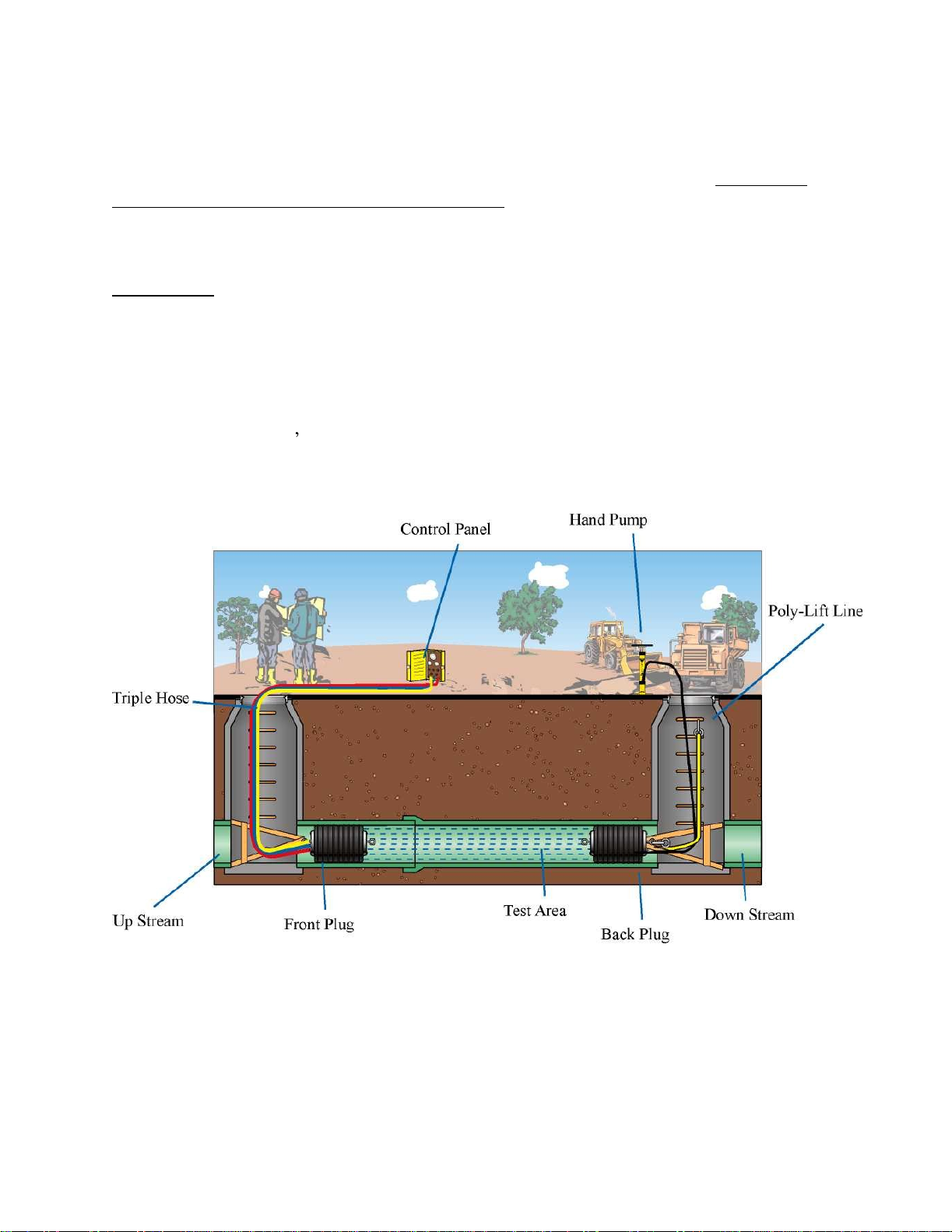
Introduction
Refer to FIGURE 1
Line Acceptance Testing consists of low air pressure testing of sewer lines using two pipe plugs. One
plug is placed in each end of a section of sewer line. The plugs are inflated to create an airti
ght seal
and the pipe (test chamber) between the two plugs is pressurized with air. A drop in air pressure
beyond the municipality s specifications indicates a leak (refer to test engineers specs). Otherwise, the
section passes. When the test is complet
ed, the test chamber is depressurized; the plugs are deflated,
and then moved to the next section of pipe to be tested.
FIGURE 1

Line Acceptance
Kit
9
PRESET TEST
PRESSURE AND BALL PRESSURE FOR
LINE ACCEPTANCE & LEAK
LOCATION
NOTE: Before the triple hose can be a
ttached to the front ball, the Air
-
Loc control panel test and
ball regulators must be adjusted.
1.
Unlatch and open the Air
-
Loc control panel (Item 1). Connect each 50 or 500 foot triple hose
quick disconnect to the fittings on the front of the control
panel according to color code.
NOTE: Leak Location Procedures use the 500 foot triple hose. Line Acceptance Procedures use
the 50 foot triple hose. This allows for faster inflation and deflation times, therefore, speeding up
the testing procedure.
2.
At the other end of the triple hose, connect the yellow and blue hoses together using two quick
disconnect nipples and a hex coupling, if available. If these types of fittings are not available,
you ll need to determine the best way to connect these two
hoses.
NOTE: Use teflon tape on all pipe thread fittings.
3.
Place the TEST VALVE in the EXHAUST position. Make sure the TEST REGULATOR and
BALL REGULATOR control knobs are turned fully COUNTERCLOCKWISE.
NOTE: The Test Regulator as well as the Ball
Regulator have spring loaded control knobs. Pull
the control knob out, turn to adjust, then release to lock.
4.
Connect the air compressor hose to the INLET AIR fitting on the control panel and place the TEST
VALVE in the OFF position.
5.
On the air compr
essor, relieve all residual backpressure. Start the compressor. Let it build to
full pressure (approx. 110 PSIG) before adjusting the TEST REGULATOR.
CAUTION: DO NOT OPERATE AT AN AIR INLET PRESSURE GREATER THAN 120
PSIG (8.2 BAR).
6.
Place the TEST VALV
E in the INFLATE position and adjust the TEST REGULATOR control
knob by turning it in a CLOCKWISE direction. Adjust the TEST REGULATOR to the correct
TEST PRESSURE" . Refer to your city/state municipal test requirements.
7.
Return the TEST VALVE to th
e EXHAUST position.
8.
Disconnect the blue and yellow hoses.
9.
Place the BALL VALVE in the EXHAUST position. Make sure the BALL REGULATOR
control knob is turned fully COUNTERCLOCKWISE.

Line Acceptance
Kit
10
10.
Place the BALL VALVE in the INFLATE position and adjust
the BALL REGULATOR
control knob by turning it in a CLOCKWISE direction. Adjust the BALL REGULATOR to
the correct Ball Inflation Pressure as indicated on the plug and/or in the
SAFETY
INSTRUCTION AND DATA BOOKLET.
NOTE: The quick disconnect coupler on th
e red hose does not need to be plugged to set the ball
pressure.
11.
Return the BALL VALVE to the EXHAUST position.
12.
Attach the 50 or 500 foot triple hose with cable restraint to the Air
-
Loc plug according to the color
coding of the hoses.
Triple hose color codes:
Red
-
Ball Inflation
Blue
-
Pressurizes the test area
Yellow
-
Monitors test pressure (on large gauge)
13.
Attach the cable from the strain relief on the triple hose to the eye bolt using the snap hook.
When line acceptance testing is completed, this cable assists in the removal of the ball from the
manhole.
14.
Lower the converted ball into the upstream manhole and insert fully into the pipe. Make
sure that the area within the pipe where the ball will be seated is cleaned of all debris or
matter that may cause an improper seal.
Ground Water Pressure Calculation
Where ground water is present in the area to be air tested, the pressure of the water
must be
Line Acceptance
Kit
11
calculated and added to the test pressure specified.
Water exerts a pressure of 0.433 PSI for each foot in height. The calculated water pressure should
be added to the pressures in the engineers specifications for a total pressure required in
air testing.
GROUND WATER CHART
FEET
PSI
METERS
Kg/CM
2
1
.43
.3
0.03
2
.86
.6
0.06
3
1.2
.9
0.09
4
1.7
1.2
0.12
5
2.1
1.5
0.15
6
2.6
1.8
0.18
7
3.0
2.1
0.21
8
3.4
2.4
0.24
9
3.9
2.7
0.27
10
4.3
3.0
0.30
TROUBLE SHO
OTING GUIDE
PROBLEM: AIR
-
LOC PLUGS WILL NOT INFLATE
Symptom:
Ball pressure gauge registers too low.

Line Acceptance
Kit
12
Cause . . . . Regulator set too low.
Solution . . Reset as required.
Cause. . . . Compressor off.
Solution . . Start compressor.
Symptom:
Ball press
ure gauge will not register.
Cause . . . . Leak in Air
-
Loc plug.
Solution . . See Air
-
Loc plug sleeve/body replacement.
Cause . . . . Leak in air hose system.
Solution . . See "Air Line System Leaks on page 14.
Cause . . . . Broken pressure gauge.
Solu
tion . . Replace gauge.
PROBLEM: AIR
-
LOC PLUGS LOSE PRESSURE
Symptom:
Reading on ball pressure gauge drops; leak is heard at the control panel.
Cause . . . . Leak in air hose system.
Solution . . See "Air Line System leaks" on page 14.
Symptom: Readi
ng on ball pressure gauge drops; no leak is heard.
Cause . . . . Leak in air hose system.
Solution . . See "Air Line System leaks" on page 14.
Cause . . . . Hose between plugs leaking or fittings are loose.
Solution . . Repair or replace hose, tighten fi
ttings.
Cause . . . . Leak in Air
-
Loc ball.
Solution . . Repair or replace.
PROBLEM: TEST PRESSURE WILL NOT BUILD
Symptom:
Test Pressure gauge registers too low.
Cause . . . . Compressor off.
Solution . . Restart compressor.
Cause . . . . Water in te
st monitor line.
Solution . . Temporarily reverse the yellow and blue hoses at the Air
-
Loc control panel to flush the
test line.
-
Trouble Shooting Guide continued on next page
-
TROUBLE SHOOTING GUIDE
(Continued)
Cause . . . . Regulator set
too low.
Solution . . Reset as required.

Line Acceptance
Kit
13
Cause . . . . Leak in pipe.
Solution . . Replace or repair pipe.
Cause . . . . Air by
-
passing balls.
Solution . . Clean line, remove debris.
Symptom:
Test pressure gauge will not register.
Cause . . . . Yellow
hose plugged.
Solution . . Disconnect the yellow hose from the Air
-
Loc reel rotary union and induce air into the
test line. This will remove any debris blocking the test line air passage.
Cause . . . . Bad leak in
pipe.
Solution . . Leak location procedure.
PROBLEM: TEST PRESSURE DROPS
Symptom:
Reading on test pressure gauge drops, leak is heard at control panel.
Cause . . . . Leak in hose system.
Solution . . See "Air Line System Leaks" on page 14.
Symptom:
R
eading on test pressure gauge drops, no leak is heard at control panel.
Cause . . . . Leak in hose system.
Solution . . See "Air Line System Leaks" on page 14.
Cause . . . . Air by
-
passing Air
-
Loc balls.
Solution . . Clean line, remove debris. See probl
em called "Air
-
Loc balls will not inflate".
Cause . . . . Leak in sewer line.
Solution . . Leak location procedures.
PROBLEM: TEST PRESSURE INCREASES
Symptom:
Reading on test pressure gauge rises.
Cause . . . . Sewer line is warmer than test air intro
duced.
Solution . . Read air testing procedures.
Cause . . . . Infiltrating water between balls.
Solution . . See "Ground Water Pressure Calculation", page 16.
Cause . . . . Air by
-
passing to test chamber.
Solution . . Check all air connections, check fi
ttings on ball.
Time Charts
APPROXIMATE TIME REQUIRED TO PRESSURIZE TO 4 PSIG (0.28 Kg/cm2)
THROUGH 50 FOOT (15.2 METERS) INFLATION HOSE
(IN MINUTES, UNLESS OTHERWISE NOTED)

Line Acceptance
Kit
14
Pipe Size
20' Reach
100' Reach
200' Reach
300' Reach
400' Reach
500' Reac
h
600' Reach
Inches
Millimeters
(6.09 M)
(30.4 M)
(60.9 M)
(91.4 M)
(121.9 M)
(152.4 M)
(182.8 M)
4
101
1 sec.
7 sec.
14 sec.
21 sec.
28 sec.
34 sec.
42 sec.
6
152
3 sec.
14 sec.
31 sec.
44 sec.
1.02 min.
1.37 min.
1.51 min.
8
203
5 sec.
28 Sec.
52 sec
.
1.4 min.
1.79 min.
2.24 min.
2.7 min.
10
254
8 sec.
39 sec.
1.37 min.
2.1 min.
2.7 min.
3.4 min.
4.1 min.
12
304
12 sec.
58 sec.
1.96 min.
2.94 min.
3.92min.
4.94 min.
5.99 min.
15
381
18 sec.
1.54 min.
3.1 min.
4.62 min.
6.16 min.
8.2 min.
9.24 min.
18
457
28 sec.
2.21 min.
4.4 min.
6.6 min.
8.8 min.
11 min.
13.2 min.
21
533
36 sec.
2.5 min.
5.9 min.
8.82 min.
11.8 min.
15 min.
17.6 min.
24
609
48 sec.
4 min.
7.9 min.
12 min.
15.9 min.
24 min.
32 min.
* The above times are approximate only. The
y re applicable to a compressor with capacity of 17.9 CFM at 100 PSI.
SAMPLE PIPE TESTING TIMES
PIPE DIAMETER/INCHES
PIPE DIAMETER/MM
MINUTES PER 100 FEET
4 101 .11
6 152 .23
8 203 .42
10 254 .53
12 304 .63
15 381 .74
18 457 .84
21 533 1.1
24 609 1.3
Form 044
-
948, Rev. C
-
ECN 06
-7552
©2006
Cherne Industries Incorporated
All Rights Reserved
TJB 6/14/06
Table of contents
Other CHERNE Test Equipment manuals

Popular Test Equipment manuals by other brands


Galaxy Audio
Galaxy Audio CHECK MATE CM-C200 instruction manual

Fortinet
Fortinet FortiTester 2500E quick start guide

Megger
Megger MET1000 user guide

Ibiza
Ibiza STROBE132LED instruction manual

Alcohol Countermeasure Systems
Alcohol Countermeasure Systems Alcolock V3 B-2 Series instruction manual

Chauvin Arnoux
Chauvin Arnoux AEMC Instruments 6470-B user manual

Dräger
Dräger Alcotest 6810 GB Operator's instruction manual

iBACheck
iBACheck i1 AA1698 Operation manual

Time Electronics
Time Electronics 8030 user manual

Fluke
Fluke NetTool Quick reference guide

Pacific Data Systems
Pacific Data Systems AlcoVUE DDS-ALV-100 User handbook

Tektronix
Tektronix MDO4104 Technical reference