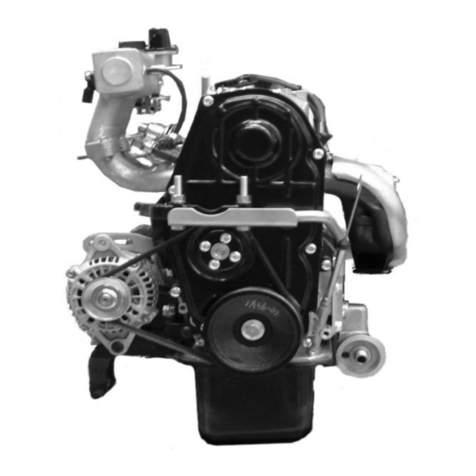
Chery SQR372 User manual

SQR7080Service Manual372EngineMechanicalSystem
CheryAutomobile Co., Ltd
1
SQR372 Engine
ServiceManual
CheryAutomobileCo., Ltd.
Forewords
Inordertohelpthetechnicalservicingpersonneltohavecorrectunderstanding andgoodcommandofthe
cute Chery ModelSQR7080 vehicle,andtomastertheskillsforfastrepairsandrationalmaintenance,a
specialeditionofthe Chery QQ TechnicalServiceManual—372EngineMechanicsDivision”is
compiledandpublished.
ThisManualgivesadetaileddescriptiononthedismounting, installation,checksandtests,adjustments
anddiagnoses,technicalstandardsandspecificationsforadjustmentsanddiagnosesofvariouspartsand
componentsaswellassubsystemsof Chery QQ372engines.ThisManualispublishedby Chery
AutomobileCo.,Ltd.
AnypartsorsectionsofthisManualshallnotbecopiedorduplicatedinwhateverformorbywhatever
approachwithoutthewrittenauthorizationofthepublisher.
Therightofinterpreting theManualbelongstotheServiceDepartmentof CheryAutomobileCo. Ltd
Editors
Marchof2004
3Specialtoolsformaintenance:
Outer appearance CodeandName Purpose
Auxiliarydevicesforengine
dismountingandchecks
Mounting ontoengine
dismountingandcheck
stand
Enginedismounting andcheckstand
Dismounting and
installing engine
Clockwisebeltwheelwrench Camshaftclockwise
belt wheeldismounting
PDF 文件使用 "pdfFactory Pro" 试用版本创建 www.fineprint.com.cn

SQR7080Service Manual372EngineMechanicalSystem
CheryAutomobile Co., Ltd
2
Springbushpulling andremoving
device
Installingcrankshaft
oil seal
Valve locking blockremovaldevice
Auxiliarytools
Dismounting and
installationof valve
spring locks
Flyingwheelfixture Dismounting and
installationof
crankshaft
Valve guidingpipepunch Removingand
installationof valve
guiding pipe
Shaftoilsealreplacer
T
Oilsealstandscrewdriver
Outer appearance Codeand Name Purpose
Crankshaftbeltwheelfixture Removeandinstall
crankshaftbelt wheel
Wrench Removeandinstall
camshaft slavegear
wheel
Replace valvespacing
adjustwasher
PDF 文件使用 "pdfFactory Pro" 试用版本创建 www.fineprint.com.cn

SQR7080Service Manual372EngineMechanicalSystem
CheryAutomobile Co., Ltd
3
Waterpumppulleyassembly
wrench waterpumpAssembly
Measuring
tools Clearancegauge,calipers,Micrometer,ruler,centesimalmeter,cylindergauge,
pressuremeter, torquewrench
Tool Pistonring dismountingdevice
Oils Engine lubricating oil, bond
Chapter2Timing Belt Service
1. Configurationdiagram
1Waterpumppulley
2Timingbeltcover
3Timingbelt
4Torsionshockabsorber
5Timingpulleydamper
6Tensioner
7Crankshafttimingpulley
※:Non-reusable part
Unit:N·m(kg·cm)
PDF 文件使用 "pdfFactory Pro" 试用版本创建 ÿwww.fineprint.com.cn

SQR7080Service Manual372EngineMechanicalSystem
CheryAutomobile Co., Ltd
4
Removetorsional vibration damper.
Removewaterpumppulley.
Removethewaterpumppulleyaccording tothe
illustration.
Removeitwithscrewdriverandwrenchaccordingto
theillustration.
SST
Removetorsional vibration damper
(1)Fixtheflywheelandpreventthegearring from
rotating.
(2)Removeboltoftorsional vibration damper.
图29
PDF 文件使用 "pdfFactory Pro" 试用版本创建 ÿwww.fineprint.com.cn

SQR7080Service Manual372EngineMechanicalSystem
CheryAutomobile Co., Ltd
5
Removetimingcovercap
Torque:6±1N.m
Removetimingpulleydamper
Removethetensioner
(1)Carryouttheoperationattheupperthrustpoint
ofcompressionofthefirstcylinderpiston
(2)Afterremoving thetimingcovercap,turnthebolt
androtatethetiminggearclockwisewithwrench,
aligntiming markofcamshafttiminggearwiththe
cammarkofcamshaftcovercap;
Attention:You canrotatetheengineclockwiseonly,
afterinstalling thepulley;
Beforeremoval,makeaarrowmarkonthepositionof
timingmark,assembleaccordingtooriginalstate.
(3)Makesurethatthecrankshafttimingpulleywheel
markisalignedwiththemarkoftheoilpump.
(4)Removethetensionerbolt,andtakeoffthe
tensioner
Timing mark
Timing mark
Clockwise
Do“mark”
PDF 文件使用 "pdfFactory Pro" 试用版本创建 www.fineprint.com.cn

SQR7080Service Manual372EngineMechanicalSystem
CheryAutomobile Co., Ltd
6
Removethetimingbelt.
[Caution] Itisabsolutelynotallowedtousescrew
driverorsomeothersharp-edgedtoolstoremovethe
belt.
Attention:Pay attention tothefollowing pointswhile
using timing belt:
-Don’tbendthebelt evenatasmallangle,
otherwiseitwillresultinropefractureinsidethe
belt.
--Service lifeofbelt isshort,don’tpollutethebelt
withgreaseandwater.
-You havenochoice butrotatetheengine
clockwiseafterinstallingthebelt.
2.7Removethecrankshafttiminggear
PDF 文件使用 "pdfFactory Pro" 试用版本创建 www.fineprint.com.cn

SQR7080Service Manual372EngineMechanicalSystem
CheryAutomobile Co., Ltd
7
3 Makecarefulanddetailedchecksonthetiming belt.Replacewithnewpartsifanyofthe
conditionsshowninthefigureoccurs.
3.1Cracksonthebacksiderubber;
3.2Cracksofteethroots,cracksclearing off thefabriclining layer;
3.3Tearsandwearsoffabriclininglayer, missing rearteeth, brokenteeth,etc.
3.4 Abnormaltearsandwearsonbeltsides
Chap
Chap
Tearsand
wears
Abnormal
tearsand wears
MIS
Drop-off
ofbeltcore
PDF 文件使用 "pdfFactory Pro" 试用版本创建 ÿwww.fineprint.com.cn

SQR7080Service Manual372EngineMechanicalSystem
CheryAutomobile Co., Ltd
8
3.5 Evenifthedamagesontheouterappearance cannotbeconfirmed,thebelt shouldbereplaced
underanyofthefollowingcircumstances:
3.5.1If thewaterinthewaterpump isleaked,whichmakesitnecessarytorefillthewater
continuously;
3.5.2 Therearemuchoil stainsonthebelt,thebeltshouldbereplacedfortherubberwillbedamaged
whenitisexpanded;
3.6 Specificationsandmodelofthetiming belt
Partnumber 372-1007081
Beltwide 25.3mm
3.7 Timingbelttensioner
Turnthebelttensionersupporting stand bolts toseeifthereareanyabnormal sound.Checktoseeif
thereareanydamagesonthecontacting surface ofthebelt.
Specificationsandmodelofthetimingbelttensioner
Partnumber 372-1007030
Wide 27.0mm
Outsidediameter φ50mm
3.8 Checktosee ifthereareanydamagesontheouter appearance
Specificationsandmodelofclockwisepulley
EFModel
Item GL、ZL、G 、Z
Diameterofcamshafttiming
gear (mm)φ110.7+0.1-0.2
Diameterofcrankshafttiming
gear (mm)φ54.65+0.7-0.13
3.9 Baffleofcrankshafttiminggear
Checktosee ifthereisanydeformation
Standardsizeofcrankshaft timing gear:
Wide 28.6mm
PDF 文件使用 "pdfFactory Pro" 试用版本创建 www.fineprint.com.cn

SQR7080Service Manual372EngineMechanicalSystem
CheryAutomobile Co., Ltd
9
4. Installation
4.1 Installationofcrankshafttiming gear
4.2 Installationoftiming belt
4.2.1 Ontheupperthrustpointofthefirstcylinder
compression
Place thecamshafttiming geararound thefrontendof
theairexhaustcamshaftsoastomakethepositioning
grooveonthegearbealignedwiththepositioningpin
ontheendsurfaceofthecamshaft.Thenusescrewsto
fixtheclockwisegear, withthetorqueof100 ±5N.m.
4.2.2 Makesurethatthepunchedmarkonthe
crankshaftclockwisepulleyisalignedwiththemark
oftheoil pump.
4.2.3 Installtimingpulleyaccordingly.
Timingmark
Timing mark
Clockwise
Timingmark
PDF 文件使用 "pdfFactory Pro" 试用版本创建 www.fineprint.com.cn

SQR7080Service Manual372EngineMechanicalSystem
CheryAutomobile Co., Ltd
10
4.3 Installthetensioner
4.3.1 Adjustthetensionofthetimingbelt
Asshowninthefigure,makethespacebetweenthe
edgeofthestretchingwheelandthewaterpumpcase
arctobeabout8mm;
Tightentheboltofthestretching wheelwitha②
torqueof25 ±3N.m.Useascrewdrivertoswingthe
stretchertowardtheright..
③Turnthecrankshaftfortwocirclestowardsthe
enginerotating direction,sothatthecamshaftpulley
andthecrankshaftpulleymatchestheclockwisemarks
respectively.
④Usehandstopressdownforabout5mm.Theforce
forpressing theclockwisebeltisabout: [Reference]
20~30 N
Notice:Whenthedeflectionofthetiming beltfailsto
meetthespecifications,thekeyistoadjustthe
above-mentionedstretcherfastening boltbywidening
thespacing.
TightentheS/Afixing boltofthestretcherwiththe
specifiedtorqueof25 ±3N.m
4Install thebaffleofthe crankshaft timing pulley
[Attention]Installthebaffle towards thedirection
shownintherightfigure.
PDF 文件使用 "pdfFactory Pro" 试用版本创建 ÿwww.fineprint.com.cn

SQR7080Service Manual372EngineMechanicalSystem
CheryAutomobile Co., Ltd
11
5Install thetimingcovercap
torque:6±1N.m
6Install thetorsional vibration damper(useSST)
1)、 Whenthereis not aflyingwheel,
Fixapartofthecrankshaftpulley.
②Payattentionnottomakethegearbeltmoving,
tightenthebolt accordingtothespecifiedtorque:
torque98.0±10N.m{10±1kgm}
2 )、 Whenthereisaflyingwheel,
Fixtheflywheeltopreventthe tooth ringfrom
turning
②Thentightenbolt oftorsional vibration damper.
PDF 文件使用 "pdfFactory Pro" 试用版本创建 ÿwww.fineprint.com.cn

SQR7080Service Manual372EngineMechanicalSystem
CheryAutomobile Co., Ltd
12
Chapter3CamshaftService
3-1.Diagram(Removalandinstallationorder fortimingbelt)
3-2Removal
Removecylinder
headcoverassembly
Removethevalvechambercovercapbolt
fromtwosidestothecentresymmetrically.
Remove②valvechambercovergasket
2Routinecheckofvalve
valveclearancestandard:
IN 0.18±0.05
Valve
clearance EX
0.25±0.05
3 Dismountthecamshaftclockwisegear
Attention·Youmustpreventthecamshaftfrom rotating.
(1) Valvecagecover
(2) Valvecagecover
gasket
(3) Camshafttiming
pulley
(4) Camshaftcover
(5) Circularplug
(6) Camshaftbearing
cap
(7) Exhaustcamshaft,
(8) Intakecamshaft,
(9) Oilseal
(10)Springretainer
(11)Wavewasher
(12)Intake camshaft
sub-gear
(13)Snapring
(14)Locknut
(15)Flange
Non-reusablepart
PDF 文件使用 "pdfFactory Pro" 试用版本创建 ÿwww.fineprint.com.cn

SQR7080Service Manual372EngineMechanicalSystem
CheryAutomobile Co., Ltd
13
Exhaust
Intake
4Removalofcamshaftcovercapandcamshaft
bearingcover
(1)Align themarksonthecamshaftgearsasshownin
therightfigure.
Setbolt
(2)Usebolttopositionthemasterandslavegearson
theairinletcamshaft,asshownintherightfigure.
Attention Inorderto eliminate theradialforce, keepthe
camshaftintheleveledpositionbeforedismounting it
(toavoidpossibledamagescausedbyexcessiveradial
forces)
(3)Removetheboltsinthesequence showninthe
rightfigure;
Removethecamshaftbearing cover
SST
(4)Removethesparkplug
(5)Removethecamshaftslavegear.Usethespecial
toolasshownintherightfigure.
Clipthecamshafttightly,andturnthegear,tokeep
thebitestateofmasterandslavegear;removethefixing
boltsofslavegear.
Attention Donotdamagethesurface ofthecamshaft.
PDF 文件使用 "pdfFactory Pro" 试用版本创建 www.fineprint.com.cn

SQR7080Service Manual372EngineMechanicalSystem
CheryAutomobile Co., Ltd
14
(6)Usetensioningapparatustoremovethebearing use
elasticsnapring, removewavewasherandteethedring.
3-3Camshaft
1Usethecalipertomeasuretheheightofthecamshaft.
If itisbelowthespecifiedlimits,makeproper
replacement.
Camshaft Unit:mm
EF
Model
Item ZL
RL GL GS
ZS
IN φ23.0-0.02-0.033
StandardEX φ23.0-0.02-0.033
IN
22.9
LimitEX 22.9
2Checksoncamshaftaxialclearance
(1)、 Whentheaxialspacing ismeasuredwitha clipper
tobelargerthanthebenchmarkvalue,thecamshaftisto
bereplaced.
Theairinlet camshaft axialclearance is0.1~0.170mm。
Theairexhaustcamshaftaxialspacing is0.1 ~
0.173mm。
Limitsforoperation:0.18mm
3-4Cleaning
1、Clearoffthesparkplugcarbonaccumulationwitha
metalbrush.
PDF 文件使用 "pdfFactory Pro" 试用版本创建 www.fineprint.com.cn

SQR7080Service Manual372EngineMechanicalSystem
CheryAutomobile Co., Ltd
15
3-5Installation
Fixthetwo φ6holesofthecamshaftgearS/A.
②Turnthe slave geartotheright,matchthemarkhole
ontheslavegearwiththemarkonthemastergear,or
alignthemarksontheslavegearwiththemarkonthe
mastergear;thenfixtheslavegearwithbolt.
(thread:M5;pitch:0.8)
SST
2、Installationofthecamshaft
Attention Sizeoftheaxialclearanceofthecamshaft
(1)、Smearlubricatingoilatthecamshaftgearsection
andthecylindercoveraxialdiametersection.
(2)、Fixthecamshaftslavegearbyroughlyadjusting on
the cylinder cover.
(3)Itisnecessarytomeasurethesize ofaxialclearing
ofcamshaft.
Exhaust
Intake
(4)Installcamshaft,thetimingmarkmustbealigned
shownastherightfigure.
(5)Smearlubricatingoil onthecamshaftassembly, the
gearsandthe cylinder headaxialdiametersection.
3Tightenthecamshaftbearingcapshownasright
figure.
4Removetheboltforfixingtheslavegearofthe
camshaftassembly.
PDF 文件使用 "pdfFactory Pro" 试用版本创建 ÿwww.fineprint.com.cn

SQR7080Service Manual372EngineMechanicalSystem
CheryAutomobile Co., Ltd
16
SST
5installationofcamshaftheadcap
Smearthefluidsealantonthecamshaftheadcapsection
(withoil groove)shownastherightfigure.
Tightentheboltsaccordingtothesequencesshownas
therightfigurewiththespecifiedtorques.
6Aftersmearing oilintheplugcapholeandassembling
surface oftheplug, useSSTtopress thepluglid
Attention·Installthepluglidshownastheright
illustration.
Keepunbiasedwithcylinderheadendsurfaceafter
pressing.
outside
7Smearengineoil ontheoil sealinstallationportof
cylinderhead,camshaftoilsealedgeofbladeand
outsidering,useM10 bolt(length50-60 mm)andSST
pressthecylinder,lower1mm than theendsurface of
thecylinder4head.
Attention ·Undertheconditionofusetheoil seal
repeatedly,pressherewithengineoiladhesiveagent
-Theoil sealshouldnotbepressedinclining tooneside.
8Installationofthetiminggearofcamshaft
Aftersmearing thefluidsealant,useSSTtoprevent
rotating,tightenthetiming gearboltofcamshaft
according toregulatedtorqueof100±5N.m.
Sealingline
PDF 文件使用 "pdfFactory Pro" 试用版本创建 ÿwww.fineprint.com.cn

SQR7080Service Manual372EngineMechanicalSystem
CheryAutomobile Co., Ltd
17
9Installationofvalvechambercovercap
Theusedbasefacing thecylindercoverofthetiming⑴
beltcovermustbecleanedthoroughly.
Installthenewbasecorrectlyintothegrooveofthe⑵
valvecagecovercap
Installvalvecagecovercaptocylinderhead⑶fromtwo
sidestothecentresymmetricallyaccording tothe
regulatedtorqueof6±1N.m
1 Usefeelergaugetocheckthethrottleclearance.
Attention·Makesuretomeasuretheclearance between
basiccircleofcamandvalveadjusting gasket.
Standardofvalveclearance:
IN 0.18±0.05
valve
spacing EX
0.25±0.05
2Whenitisbeyondthebenchmarkvalue,the
adjustmentwasherhastobereplacedandtheclearance
shouldbeadjusted.
Attention Thevalvenumberthatgoesbeyondthe
benchmarkvaluehastoberecorded,andtheresultof
measurementsshouldberecordedas well
(1)Useacalipertomeasureandadjustthethickness of
theseparationcushion.
2.18 2.40 2.62
2.20 2.42 2.64
2.22 2.44 2.66
2.24 2.46 2.68
2.26 2.48 2.70
2.28 2.50 2.72
2.30 2.52 2.74
2.36 2.58 2.80
2.34 2.56 2.78
2.32 2.54 2.76
2.38 2.60
(2)Selectproperseparationcushiononthebasisofthe
throttlethrustingrodbenchmarkvalues.
IN
Selectedcushionthickness=removedcushion
thickness +(measuredthrottlespacing –0.18mm)
EX②
Selectedcushionthickness=removedcushion
thickness +(measuredthrottlespacing –
0.25mm)
[Reference]thereare32kindsofshimisthickness ,
shownastheillustration
PDF 文件使用 "pdfFactory Pro" 试用版本创建 www.fineprint.com.cn

SQR7080Service Manual372EngineMechanicalSystem
CheryAutomobile Co., Ltd
18
Forword
lower
(7)Usetheselectedadjustinggaskettoadjustthe
throttleclearance.
Attention Install thefeeler withtheidentification mark
facing downwards.
4.Cylinderhead
4-1Configurationdiagram(Dothefollowingoperationsintheproceduresforthedismountingand
installationofthecamshaft)
(1)Sparkplug20±1Nm
(2)Cylinderhead
(3)WeathersealI
(4)Cylinderheadgasket
(5)Adjustshim
(6)Valvelifter
(7)Keeper
(8)Valvespringseat
(9)Valvespring
(10)Intake valve
(11)Exhaustvalve
(12)Valveoil seal
(13)Valveseat
(14)Valveguide
※:Non-reusable part
Unit:N·m(kg·cm)
PDF 文件使用 "pdfFactory Pro" 试用版本创建 ÿwww.fineprint.com.cn

SQR7080Service Manual372EngineMechanicalSystem
CheryAutomobile Co., Ltd
19
4-2Dismounting
1、Removalofsparkplug
2Thereare8cylindercoverbolts.Intheprocess ofremoving the
cylinder,pleasefollowthesequencesshownastheright
illustration, loosenthe boltsonebyone evenlyand gently.
3Removalofthecylinderdustproofsealingandcylinder
coverbase.
Attention Thecylindercushioncannotbeused
repeatedly.
4Removalofthrottleadjustingseparationcushionand
valvethrustingrod
5Usespecialtoolstoremovethevalvespringlocking
block,throttlespring stand,valvespring,INvalveand
EXvalve
6Removalofvalveoilsealandvalvespring washer
4-3Clearing
1Theaccumulatedcarbonresiduecoveredonthevalve
mustbecleared.
2Usescrapertoclearthecylindercover,theairinlet
andexhaustbranching pipesurfacesandbottoms
Attention
Donotdamagethecylindercoversurfacebyscraping
duringtheprocess ofclearing.
Donotdropfilthintotheairinletandthewaterchannel.
SSTforvalveoilseal
PDF 文件使用 "pdfFactory Pro" 试用版本创建 ÿwww.fineprint.com.cn

SQR7080Service Manual372EngineMechanicalSystem
CheryAutomobile Co., Ltd
20
4-4Routinechecks
4-4-1Cylindercover
1Usethestraightknifesharpedgerulertomeasurethe
levelness atvariouspointsasshowninthefigure.
Cylindercover0.10mm
Airinletbranchingpipesurface0.10mm
2Useasquarerulertomeasuretherightangleofthe
valvespring.Replacethespring ifit failstomeetthe
specifications.
[Limit] 1.2mm
3Measurethefree stateofspring
[Benchmarkvalue]37mm
4-4-3Throttle
Routinechecksonthrottles
1.Checktosee iftherearesomedeformations,obvious
tearsandwears
RoutinechecklistonvalveUnit:mm
Item Standard Limit
IN
0.85~1.41 ___
Wide E
X
1.07~1.36 ___
IN
1.0±0.2 0.75
Widthofvalvetop
E
X
1.0±0.2 0.75
Width
Measure outside
diameter
PDF 文件使用 "pdfFactory Pro" 试用版本创建 ÿwww.fineprint.com.cn
Other manuals for SQR372
1
Table of contents
Other Chery Engine manuals
Popular Engine manuals by other brands

Siemens
Siemens 1LA8 operating instructions

BRP
BRP ROTAX 125 MAX DD2 evo Installation instructions and operators manual
Briggs & Stratton
Briggs & Stratton 110400 Operating & maintenance instructions
Siemens
Siemens SINAMICS S120 Function manual
GGP
GGP RS Operator's manual
Grizzly
Grizzly H5377 Wiring diagram

