Chevrolet CT525 User manual

CT525
CIRCLE TRACK RACING ENGINE
TECHNICAL MANUAL

2 |
CONTENTS
Copyright July 2006
General Motors Company
Revised February 2023
This Technical Manual is dedicated to the memory of
Robert E. (Bob) Cross
1957-2010
Introduction, Legal Information & History --------------------------------------- Pg. 3
Position Statement, Where to Buy, Warranty------------------------------------ Pg. 4
Engine Package Overview ----------------------------------------------------------- Pg. 5
Engine Priming, Start up and Break in instructions ---------------------------- Pg. 6-7
Sealing System ------------------------------------------------------------------------ Pg. 8
Engine Components
Cylinder Block + Int. Components --------------------------------------------------------- Pg. 8-9
Camshaft--------------------------------------------------------------------------------- Pg. 10
Timing Chain + Gears & Front Covers------------------------------------------------------ Pg. 11
Cylinder Head + Valves & Springs --------------------------------------------------------- Pg. 11-12
Pushrods +Rocker Arms & Lifters --------------------------------------------------------- Pg. 12
Ignition System--------------------------------------------------------------------------- Pg. 13
Plugs, Wires & Boots---------------------------------------------------------------------- Pg. 14
Oiling System----------------------------------------------------------------------------- Pg. 14-16
Balancers -------------------------------------------------------------------------------- Pg. 16
Cooling System --------------------------------------------------------------------------- Pg. 17
Accessory drive system ------------------------------------------------------------------ Pg. 17
Intake Manifold + Carburetor + Breather -------------------------------------------------- Pg. 18
Flywheel, Starter, and Fuel Pump Requirements ------------------------------------------ Pg. 19
Engine Specifications ----------------------------------------------------- Pg. 20
Service Parts List --------------------------------------------------------------------- Pg. 21
CT525 Crate Engine ------------------------------------------------------------------- Pg. 22

3|
INTRODUCTION
LEGAL INFORMATION
Chevrolet Performance is committed to providing
proven, innovative performance technology that is
truly More than just Power. Chevrolet Performance
Parts are engineered, developed and tested by the
factorytomeetyourexpectationsforfitandfunction.
Visitourwebsiteatwww.ChevroletPerformance.com
for the Chevrolet Performance Parts authorized
Center near you.
This book provides general information on components
and procedures that may be useful for engine break-in
andtechnicalinspection.Observeallsafetyprecautions
and warnings as needed. Wear eye protection and
appropriate protective clothing. When working
under or around the vehicle support it securely with
jack-stands. Use only the proper tools. Exercise
extreme caution when working with flammable
corrosive, and hazardous liquids and materials.
Some procedures require special equipment and
skills. If you do not have the appropriate training,
expertise, and tools to perform any part of the
installation then contact a professional.
This publication is intended to provide information
about your circle track engine and related components.
The publication also describes procedures and
modications that may be useful during the installation.
It is not intended to replace the comprehensive service
manuals or parts catalogs which cover General Motors
engines and components. Rather, it is designed to
provide supplemental information in areas of interest
and to do-it-yourself enthusiasts and mechanics.
This publication pertains to engines and vehicles
which are used off the public highways except where
specically noted otherwise. Federal law restricts the
removal of any part of a federally required emission
control system on motor vehicles. Further, many states
have enacted laws which prohibit tampering with
or modifying any required emission or noise control
system. Vehicles which are not operated on public
highways are generally exempt from most regulations.
As are some special interest and pre-emission vehicles.
The reader is strongly urged to check all applicable
local and state laws.
HISTORY
GM has a long history of providing the engine of choice
for circle track racing. The introduction of the small
block Chevy in 1955 started it all. Production parts
were durable, and the engines were plentiful. In the
1960’s, Chevrolet started producing HD parts for racing
activities and a whole industry was started.
Over time, the competitive nature of racing drove costs
increasingly higher and sanctioning bodies found it
increasingly difcult to police the competitors. In the
1990’s, several tracks and individuals took Chevrolet’s
successful crate engines designed for the street
and adapted them for circle track applications. The
potential for cost savings was tremendous.
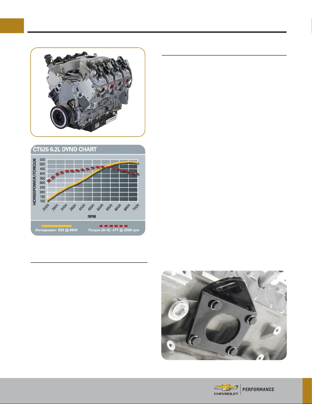
Based on the success of the 3 traditional Gen0/1 Small
BlockCTengines,GMRacingandChevroletPerformance
Parts engineers have developed a modern production
engine into a circle track race motor. The base engine
for the CT 525 comes from the highly successful latest
generation of the LS engine family, the 6.2L LS3 Gen 4
V-8. This engine is then up-tted with a Circle Track
Racing Oil Pan, Open Plenum Carbureted 4 barrel Intake
Manifold, ASA Camshaft, and a Ported Left side Valve
Cover for breathers.
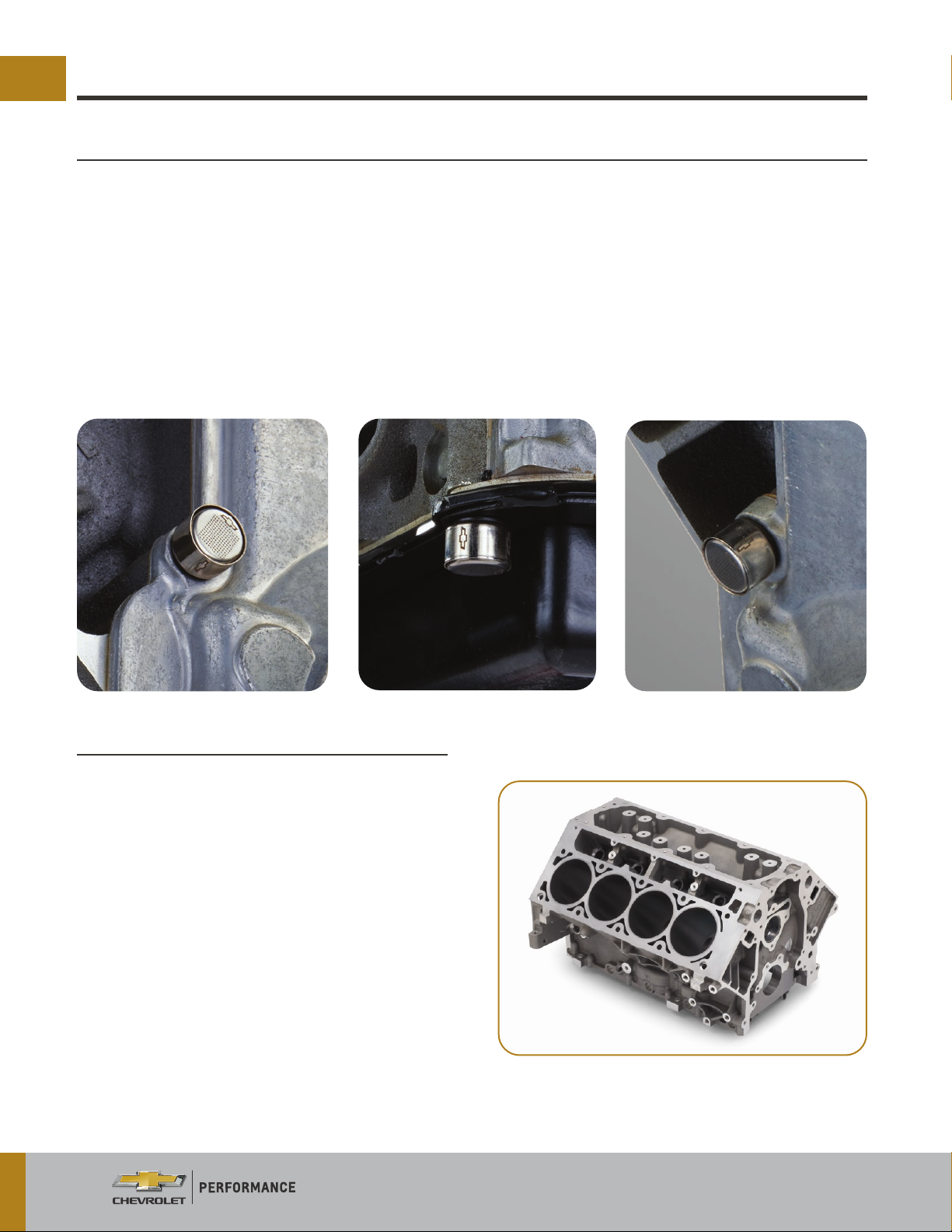
Each engine is assembled with all new parts on a
production line to keep costs down. The engines then
are up-tted with special oil pans, valve covers and
sealing bolts. Factory sealing of the engines are one of
the keys to the success of the program as this makes it
difcult to tamper with the engine and helps maintain
equality among the competitors. If used as directed,
the engines should provide several seasons of use with
minimal maintenance.

4 |
WHERE TO BUY
WARRANTY
Circle track crate engines can be purchased from any GM Dealer in the USA, Canada and other countries.
Our recommendation is to contact an authorized Chevrolet Performance Parts dealer which is more familiar
with GM’s high-performance parts line. Contact 1 (800) 468-7387 or www.chevroletperformance.com to
find a dealer near you.
Circle track crate engines have no warranty. They are intended for off-road racing activities only.
CIRCLE TRACK ENGINES — POSITION STATEMENT
General Motors does not endorse nor encourage any
internal engine repairs or modications to any sealed
racing engine in the field. Due to the competitive
nature of the intended application, any maintenance or
repairs that require the sealing bolts to be removed for
any reason deem the engine non-factory assembled
and the competitiveness becomes questionable.
Some sanctioning bodies or racing groups may allow
rebuilding or modications but that sanctioning body
or group is solely responsible for verifying the integrity
of the engine from that point forward.
Circle Track racing engines from Chevrolet
Performance Parts are equipped from the factory
with tamper-resistant seals. Chevrolet Performance
does not endorse nor encourage any internal engine
parts replacement, repairs or modications to any
sealed racing engine. If the GM-supplied engine seals
are removed for any reason, Chevrolet Performance
cannot ensure engine equality and consistency for
performance or durability. In the event where internal
repairs become necessary, Chevrolet Performance
encourages the engine owner to consult with the local
promoter/presiding track ofcial to determine if the
engine must be replaced with a new, factory-sealed
engine. Replacement is the Preferred/Recommended
process in order to maintain the integrity of a “Sealed
Crate Engine Program".
Chevrolet Performance does not supply seals for a
rebuilt factory engine, nor does it endorse or approve
independent engine rebuilders as “GM-authorized”
engine rebuilders.
All Chevrolet Performance crate engines, including
circletrack,aremanufacturedwithallnewcomponents.
A non-ring cold test is conducted as part of end of
assembly line testing on all crate engines. During
this test the engine is spun at low speed and various
parameters, including compression, are checked
against established standards to ensure that quality
requirements are met.
Chevrolet Performance requires proper “break in”
procedures to be followed, as outlined in owner's
manuals or instruction sheets. Diagnostic testing such
as “leak down” tests are not a reliable indication of
engine output or durability to perform as promoted.
Chevrolet Performance crate engines are tested
to generate advertised power and torque values
are representative of engines in series production.
Observed results vary.

5|
GM 525 CIRCLE TRACK PACKAGE
T h e L S 3 C T 5 2 5 e n g ine p ack a g e w a s de v e lo p e do f f th e
powerful production Corvette LS3 enginepackage
and is sold as P/N 19434598. It is soldcomplete,
intake to oil pan, including coil packs. It does not
include the ignition system, fuel pump, wiring,
exhaust manifolds or water pump.
The LS3 engine is 6.2 Liters (376 Cubic Inches),
using a 4.065" bore and 3.62" stroke crank mated
with forged aluminum pistons and powder metal
forged rods. Compression ratio is 10.7-1.
Several parts are changed from the stock engine
to make up the Circle Track package. A single plane
4bbl intake manifold, ASA Camshaft profile, circle
track type oil pan, ATI balancer, forged pistons, ARP
Rod Bolts and specific engine breathers round out
the package. The ASA camshaft and free flowing
heads boost HP to 533 HP @ 6600 RPM and torque
to 477 lb.-ft @ 5200 RPM. Dyno testing was done
with stepped headers and a 750 CFM HP carburetor.
Headers were 1 3/4" tube 10" long transitioning into
1 7/8" tube for total length of 32" long and exiting
into 3 1/2" collector.
Camshaft specifications are .226 intake & .236
exhaust @ .050 duration along with a .525" lift allow
this package to breathe. The engine is all aluminum
weighing in at 415 lbs dry.
All LS style engines have different motor mount
bolt hole locations than a traditional small
block Chevrolet. Aftermarket companies have
brackets that will adapt the LS bolt pattern to
a small block mount or to a circle track style
chassis mount. The rear bell-housing pattern
is the same as small block except the RH upper
bolt boss is deleted. Make sure you install all the
bolts in the bell-housing for full strength. Rear
bell-housing bolts are metric size threads M-10
x 1.5-6H (length determined by bell-housing). All
conventional Chevrolet bell-housings will bolt to
the LS engines with the use of longer dowel pins
and correct metric bolts.
KRC Racing Motor Mount Adapter shown
Engine Installation
Engine Specications

6 |
RECOMMENDED BREAK-IN PROCEDURE
Start-up is critical to help ensure engine life. This procedure was written with the intent to provide a quick
reference and guideline to starting a new or rebuilt engine if a dynamometer (dyno.) is not available. If you
are using a dyno., refer to the dyno operator’s guidelines for start up and initial break in of the engine.
1. Safety First! Make sure you have proper tools as well as eye protection. If the car is on the ground, be
sure the wheels are chocked and the transmission is in neutral.
CAUTION! This engine assembly needs to be filled with oil! After installing the engine, ensure the
crankcase has been filled with the appropriate motor oil to the recommended oil fill level.
2a. Be sure to check the oil level in the engine and prime the oil system, then recheck the oil level. It should be
at the bottom of the oil level plug when the plug is threaded in the pan. Correct oil level with this circle track
oil pan is achieved when the oil just touches the bottom of the indicator plug with the plug fully threaded
into the oil pan bung. [The pan alone holds 6 qts] the remote oil filter and cooler will be additional oil. Use
as large of an oil filter as possible, ensuring a minimum of 10 Gallons Per Hour (GPH) flow capacity and 25
micron filtration rating. A BRAND NEW ENGINE OIL COOLER MUST BE USED, WITH A MIN FLOW OF 10 GPM. It
is recommended that Mobil 1 0W-40 motor oil be used (engine oil must meet Dexron R specification which
will be indicated on the oil label, Mobil 1 meets this specification). Also check and fill as required any other
necessary fluids such as coolant, power steering fluid, etc.
2b. This engine MUST be primed with oil before starting. The use of Kent-Moore engine preluber kit J45299
is the preferred process for priming.
Note: A constant and continuous flow of clean engine oil is required in order to properly prime the engine.
Be sure to use approved engine oil, as specified. Do not overfill!
1. Install the oil filter and tighten.
2. Locate and remove the engine block left front oil gallery plug (1).
3. Install the M16 x 1.5 adapter P/N 509375.
4. Remove the engine oil filter, and fill with clean engine oil.
J 45299 Engine Preluber

7|
RECOMMENDED BREAK-IN PROCEDURE (CONTINUED)
5. Install the flexible hose to the adapter and open the valve.
6. Pump the handle on the J45299 preluber in order to flow a minimum
of 1-1.9 liters (1-2 quarts) engine oil. Observe the flow of engine oil
through the flexible hose and into the engine assembly. The engine
will be primed after a small amount of pressure change is seen on
the in car oil pressure gauge while pumping J45299
7. Close the valve and remove the flexible hose and adapter from
the engine.
8. Apply approved thread sealer and Install the oil gallery plug to the
engine and tighten to 60 N·m (44 lb ft).
Top-off the engine oil to the proper level.
Due to the empty hoses, oil filter, and oil cooler, it is much more
important to prime this set up vs. a street driven or OEM engine.
In the absence of a preluber kit, the following process can be used. Install an oil pressure gauge (the existing
oil pressure sensor location at the upper rear of the engine may be used). Disconnect fuel and the ignition
control system (removing power from the ignition control module is recommended). Note: Make sure that no
fuel or ignition power can be provided to the engine. Remove all of the spark plugs which will reduce the load
on the engine bearings and starter motor during the oil priming sequence.
2c. Once, the fuel and ignition control systems have
been disconnected, crank the engine using the
starter for 10 seconds and check for oil pressure. If
no pressure is indicated, wait 30 seconds and crank
again for 10 seconds. Repeat this process until oil
pressure is indicated on the gauge.
3. Dyno break-in is recommended.
4. Reconnect the fuel and ignition control systems.
Start the engine and listen for any unusual noises.
If no unusual noises are noted, run the engine from
idle to approximately 1800 RPM, then 0% throttle
back to idle. Perform this sequence continuously
up and down until normal operating temperature is
reached.
DO NOT RUN THE ENGINE AT A CONSTANT HIGH RPM
WITH NO LOAD! VARYING RPM, IDLE TO 1800 RPM UP
AND DOWN IS ALL THAT IS NEEDED.
5. When possible, you should always allow the engine
to warm up prior to driving. It is a good practice to
allow the oil sump and water temperature to reach
180°F before applying heavy loads or performing
hard acceleration runs.
6. Adjust Carburetor (carb.) settings. Idle mixture
screws, base idle, floats, Etc.
7. After rst 30 minutes of the engine running, re-set
carb. adjustments.
8. Drive the vehicle at varying speeds and loads for
first 30 laps. Be sure to avoid Wide Open Throttle
(WOT) and sustained high RPM accelerations
9. Run 5-6 medium-throttle accelerations to about
4500 rpm and let off in gear and coast back down to
2000 rpm, after each acceleration.
10. Perform several (WOT) accelerations to 5000
rpm. Allow the engine to return to idle, with the
throttle blade shut. This procedure will assist in
seating the rings properly.
11. Change the oil and filter. Replace the oil following
the procedure in step 2a. from above. Use as large
of an oil filter as possible, ensuring a minimum of 10
Gallons Per Hour (GPH) flow capacity and 25 micron
filtration rating. Inspect the oil and oil filter for
any foreign particles to ensure that the engine is
functioning properly.
12. Drive the next 25 laps without high rpm’s (below
5000 rpm), hard use, or extended periods of high
loading.
13. Change the oil and filter again.
14. Your engine is now ready for racing.
J 45299 Engine Preluber

8 |
ENGINE COMPONENTS
Sealing System
TheCT525CircleTrackCrateenginesaresealedfromthe factory withfour anti-tamperboltcoverassemblies.
The CT525 Circle Track engine is fitted with the seal assemblies on the intake manifold, front cover, and oil
pan. These are specially designed to deter access to internal engine components. GM Replacement bolt
cover assemblies are not sold to the public. This ensures the integrity of the race program. See Rebuild
Section to understand repairs, rebuilds and replacement options. Each Stainless Steel seal assembly has a
unique encrypted code, laser marked onto the cap along with a Chevrolet Bowtie trademark logo. The base
of each seal assembly has the Chevrolet Bowtie trademark logos in four locations on the outer surface.
Tech inspectors can determine if there has been any creative activity going on with a given engine in a
matter of seconds with this new system. A handheld digital camera takes a photo that is in turn decoded by
proprietary software that can reside on a laptop computer.
Cylinder Block
The LS3 cylinder block is made from cast
aluminum. Cast in liners are finish machined and
honed to 103.25mm (4.065"). It has 6 bolt cross-
bolted main caps that provide a solid foundation
for the crankshaft and entire engine package.
Deck Height is 9.240".
Note: There are 8 oil passageways in the top of the
block above the camshaft. These are sealed by the
stock LS3 valley tray. These are part of the Active
Fuel Management system (AFM) used on other
engines that share the block. The Corvette LS3
does not use AFM, so these oil passageways are
sealed off when the valley tray is installed.
Caution: Do not use any other valley plate or
major oil hemorrhaging will occur and the engine
will fail.

9|
ENGINE COMPONENTS (CONTINUED)
Crankshaft
LS3 engine had a cast iron crankshaft with rolled
fillets and one-piece rear seal. Stroke is the same
as other cranks, 3.62". The thrust is located on
# 3 main or the center of the crank. Main journal
size is 2.558" Rod journal size is 2.098" See Specs.
The crankshaft incorporates a 58X trigger wheel
at the rear for accurate crankshaft timing. It is
factory balanced for the rod and piston weights.
Crankshaft weight with the crank timing gear
on it is approximately 51 Lbs. Due to crankshaft
balancing, crank weight can vary.
Connecting Rods
The connecting rods are powdered metal with
cracked caps. LS3 rods are 6.098" long.
Oil Pump
The LS3 uses a standard Gearotor oil pump design.
This is one of the most efficient oil pump designs
used today. Normal oil pressures are 15+ lbs at
1100 RPM idle and 40+ lbs @ 5000+ RPM.
Figure 01 is a picture of the new oil pump.
In figure 02 the cover is removed to show the
Gearotor gears and how the center gear locates
on the crankshaft to drive the outer gear. The
fitting on the lower right (Fig 02) also shows the
bypass valve and spring.
Pistons & Rings & Rods
Pistons are forged aluminum for 103.25 mm
(4.065") bores and use full floating pins. They have
no valve reliefs and can only handle up to .525" lift
camshafts with less than 340 degrees duration.
The rings are a low tension design with a 1.5mm
top, 1.5mm second and a 2mm oil ring. The rod
bolts are ARP P/N 134-6006.
Fig 1
Fig 2

10 |
ENGINE COMPONENTS (CONTINUED)
Cam Shaft
The camshaft is a hydraulic Roller design. It is made from Billet steel. The camshaft specications were developed
from the original LS-1 ASA program. The cam specications are .226 intake & .236 exhaust duration @ .050" lift
and .525" valve lift. This camshaft allows the engine package to take full advantage of the LS-3 rectangular port
cylinder head breathing.
Cam duration is 226 degrees intake and 236 degrees exhaust @ 0.050 in.
Lope separation is 110 Degrees
Intake lift at lobe is .3075 In.
Exhaust lift at lobe is .3077 in.

11|
Timing Gears
The stock LS3 engine uses a 58X-4X crank and
timing arrangement with a single bolt camshaft
gear. The camshaft gear is replaced in the CT525
package with the 2006 LS2 3 bolt 4X cam gear
which is compatible with the 58X crank trigger.
In 2006 GM changed the timing arrangement from
24X-1 to 58X-4. The change to 58X-4 was more
in line with industry standards and can allow the
engine to operate in a reduced capacity mode, if
the crankshaft sensor fails.
The 88958770 ASA camshaft uses the earlier 3
bolt cam gear retaining method. A 2006 LS2 timing
gear is both compatible with the 3 bolt design and
the 4X cam sensor.
The 3 bolt camshaft gear P/N 12586481 is installed
with 3 P/N 12556127 bolts. If you need to replace
the cam sensor there are 2 different designs used
in the LS3. P/N 12627501 is the 1st design. 12613158
is the second design.
Below is picture of 4X reluctor 3 bolt camshaft
timing gear used in CT525.
Timing Chain
The CT525 package uses the stock LS3 timing
chain. This chain has held up good under severe
duty applications.
Front Cover
The front cover is die cast aluminum and
incorporates the cam sensor in it. The LS3 uses
as 4X timing gear along with a 58x crank gear for
precise timing control.
Cylinder Head
Cylinder heads are made from Cast aluminum. The
revised cylinder heads are what make this engine
so powerful. The LS3 head is based partially off
the LS7 design. The design change from Cathedral
port to rectangular port increased the flow
potential tremendously but requires an offset
intake rocker arm.
Combustion chamber is 70cc. Using 55mm (2.165")
Hollow stem intake valves and 40mm (1.59") solid
exhaust valves. Intake port runners are 260cc and
the exhaust port runners are 98cc. The intake
port flows up to 310 CFM stock.
The valve angles are 15 degrees. The valve location
has been moved to accommodate the huge 2.165"
intake valve and 1.59" exhaust valve. The intake
valve is now .854" from piston center line and the
exhaust is 1.158" from the centerline.
Note: LS3 heads cannot be used on bores smaller
than 4" diameter.
ENGINE COMPONENTS (CONTINUED)

12 |
Valve springs
The LS3 engine uses the Bee-Hive style valve spring which is superior to other type springs for this application.
It is lightweight and can control the valve train very well. The original CT525 was built with a yellow valve
spring, and later changed to a blue spring due to part availability. In late 2020, the spring color was changed
to a natural color with an ivory stripe. The latest P/N is listed in the parts below. GM has performed extensive
testing to verify there is no performance differences between any of the springs. It is 1.27" in diameter, 1.06"
at the top and 1.8" installed height. Spring pressures are 90lb +/- 13 lb at .525 valve lift.
Pushrods & Rocker Arms
The LS3 engine uses pushrods made from 1010 steel.
They are 7.325" long. LS3 engines use two different
rocker arms. Both are 1.7:1 ratio investment cast
with roller pedestal. The intake rocker arms are
off-set .200" P/N 12696105. The exhaust rocker
arms are straight P/N 12681275. Both use a roller
trunnion design but do not have a roller tip.
The rocker arms are located by a coined bar that
sits on top of the head machining and has the Half
Moon locators for each rocker arm. Each rocker
arm is secured with a special 8mm bolt.
Lifters
The LS3 525 Engine uses stock hydraulic lifters.
They are secured and located with these plastic
anti-rotation locator trays. There are 4 of the trays
in the engine which handle 2 cylinders. Each tray is
secured with a single special designed 8mm bolt.
The special bolt holds the trays in place and allows
them to move slightly. They are also captured in
the block by head.
ENGINE COMPONENTS (CONTINUED)

13|
Ignition System
The CT525 uses production LS3 coils along with
an ignition box P/N 19355863. The ignition box
will need to be programmed with a laptop for
the correct timing advance curve. A CD disk is
included with each box along with a data cable.
The CD program is compatible with most Windows
operating systems including Vista. Programming
is quick and simple. Open the program, then follow
these steps.
1. You will need to have 12 volts power and ground
hooked up to the box to transfer the new advance
curve to the box.
2. GM recommends the timing be set at 27 degrees
@ 3000 RPM for best power with 91 octane fuel.
3. Set your advance curve for 5-6 degrees @
400-500 RPM and then set your next point to 27
degrees @ 3000 RPM. This will give you a straight-
line advance. Program the 27 degrees flat out to
8000 RPM in the table.
4. Program the upper Map grid to Zero timing.
5. Then set both high and low Rev Limits to 6600
RPM. (Click on the RPM and a box will come up that
you scale up or down.
6. Save the settings and then transfer the program
to the box.
7. Do not install one of the supplied Pills in the box.
The box will revert back to the timing curve of the
Pill and you will lose your programmed curve and
have to redo it. Some tracks or sanctioning bodies
may require use of their own preprogrammed
Pill or ignition box. Check with your track or
sanctioning body rules for clarification.
See Fig 3a & 3b for pictures of the 19355418
Ignition box and wiring harness.
ENGINE COMPONENTS (CONTINUED)
Fig 3a
Fig 3b

14 |
ENGINE COMPONENTS (CONTINUED)
Spark Plugs, Wires and Boots
Recommended spark plugs are AC Delco P/N 41-985
and gapped to .040"
Firing order is 1-8-7-2-6-5-4-3. Production spark
plug wires have a fitting that locks into the coil so it
doesn’t fall out. GM highly recommends using spark
plug wire heat covers since newer design chassis’s
route the headers closer to the engine. These can
be purchased inexpensively from Summit P/N DEI-
0105502 or Speedway Motors P/N 698-2524. Those
part numbers come 8 to a package and are 6" in
length. See Fig 04 below.
Oiling System Requirements
GM puts 5W-30 Mobil 1 oil in the stock LS3 as
delivered in the Corvette. 0W-40 Mobil 1 (oil must
meet Dexron R specication) oil is the recommended
oil for the CT525 circle track engine package.
Circle Track Oil Pan
The engine comes with a steel wet sump oil pan
P/N 19243065 that uses 8 quarts of oil. It has a RH
kick out and 6 trap doors. (Fig 05) The oil pan is 4
1/2" deep. Total depth compared to standard small
blocks is 7" as measured from the crank centerline.
The engine still uses the stock windage tray along
with the oil pan windage tray to reduce the amount
of aerated oil in the engine.
Oil Filter and Remote Routing. On the LH rear side
of the pan are two -10 outlet fittings. The front -10
fitting is oil feed from the oil pump (out) to the oil
filter. Oil lines from the oil filter and oil cooler (in) to
the rear -10 fitting to feed the engine.
See Fig 06 Below.
Fig 4
Fig 5
Fig 6

15|
ENGINE COMPONENTS (CONTINUED)
Oil Level. Oil level is critical to proper engine life.
When engine oil is full, the oil will just touch the
bottom of the access bolt on the RH side of the pan.
(Fig 7a & 7b) This keeps the oil below the windage
tray. DO NOT over fill the system.
Figure 7b shows a picture of the fill plug from the
inside of the pan. The bottom of the plug is just
below the windage tray. Oil level should just touch
the bottom of this plug.
Oil Temperature Sensor Fitting. The oil pan has
a 1/2 " NPT fitting on the Left side in the center
for an oil temp sensor. This can be used for an
oil temp gauge sensor or be plugged. It is highly
recommended you use an Oil temp gauge and keep
the temps below 260 degrees. (Fig 08)
Block Dipstick Plug. The circle track pan does
not use the stock dipstick. Plug P/N 12667039 is
installed in the stock machined hole on the RH side
of the block. See Fig 09.
Oil Filter Requirements
Make sure you use the largest filter you can with
minimum of 10 GPH per minute and 25 micron
rating such as a Fram HP1 or larger filter. A remote
filter adapter is required with minimum of -10 AN
lines. Several manufactures make good and easy to
mount adapters.
Oil Cooler
A remote oil cooler is mandatory. It should be
located in front of the radiator It should be a
minimum of 7" x 14" with minimum flow of 10 GPM
and -10 AN or 1/2" inlets. You want to see between
200-270 degree oil temps.
Oil Pressure Gauge Adapter
An oil pressure gauge port is located at the left
rear of the valley plate. The factory uses a M-16 x
1.5 metric thread so you will need an adapter.
Autometer sells a metric to NPT adapter under
P/N 2268. This adapter is required to convert
the production sensor holes M16x 1.5 threads to
1/8" NPT. See Fig 10. Be sure use the copper seal
included with the adapter or leaks may occur.
Fig 7a Fig 7b
Fig 8
Fig 9 Fig 10

16 |
ENGINE COMPONENTS (CONTINUED)
Oil Pressure Sender. With the addition of a 1/8" pipe
tee, both the fuel pump oil pressure sensor and the
in car oil pressure gauge can be plumbed. See Fig 11.
The oil sender seen in Fig 11 is for the fuel pump
shut off. See Fuel Pump section.
Note: This is very important for safety.
Balancer Installation
An ATI Balancer, P/N 917279, with special durometer
rubber is included and recommendedfor circle track
applications. The dampener is 6 3/4" in diameter
and the smaller 6 rib pulley drives the serpentine
system 10% slower. This balancer design does not
incorporate the Air Conditioning pulley, it only has
provisions for the water pump pulley. Fig 12.
Important: Tighten the 6 counter sunk bolts to 16
ft lbs and the 3/8" 12 point bolts to 28-30 ft lbs.
Crankshaft Bolt. Fig 13 – An ARP bolt P/N 234-2503
is required. Use red Loctite on the threads and add
silicone sealer on both sides of the washer when
installing. Torque to 235 ft lbs using Ultra Torque
Fastener Assembly Lubricant.
Crankshaft Balancer Pin. GM production does not
use a keyway slot to locate harmonic balancers like
the older small blocks did. GM factory balancers are
zero balanced and do not use timing marks like a
standard small block so they don’t require a keyway
to locate them. The circle track engine requires a
pin to locate the ATI balancer. When using an ATI
balancer the crank needs to be drilled. See Fig 14.
The CT525 crank is drilled from the factory and a
3/16" x .500" (.185") pin is installed. This secures
the ATI balancer so it doesn’t slip.
GM discovered the need to secure the balancer on
the original LS1 ASA program. The engineers found
that when engines hit the RPM chip repetitively the
balancer would slip on the crankshaft. This would
cause damage to the crank and everything that
was driven off the front of the engine.
Fig 11
Fig 12
Fig 13
Fig 14

17|
ENGINE COMPONENTS (CONTINUED)
In Fig 15 you can clearly
see the pin. It is located
at the 2 o’clock position
in the picture.
Cooling System
Radiator. An adequate radiator is recommended
that can keep the engine within 180-210 degrees
water temperature is mandatory.
Surge Tank. A Surge or Expansion tank with the
CT525 package must be used. It can be attached
to the RH bar above the water pump thermostat.
The bottom of the surge tank should be hooked to
the front heater hose outlet. The rear heater hose
outlet can be plugged. Important: Route the LH
upper head air bleed line to the upper top of the
surge tank. (This will insure air is properly bled
from the engine). It is also recommended to run a
-4 line from the RH top side of the radiator to the
surge tank as well. See Fig 16.
Note: Failure to route LH upper head air bleed
line to surge tank will result in engine failure.
Water pump
A water pump is required. GM P/N 12725009 or
equivalent is required. Torque the bolts as follows:
First pass 15N•m 11 lb ft
Final pass 30 N•m 22 lb ft
Electric Fan
An electric fan is recommended to keep the engine
within a 180-210 degree range.
KRC Racing also makes a front end accessory drive
kit with a standard rotation water pump and a fan
mounting flange on the water pump to allow the
use of a mechanical fan if desired.
Serpentine Belt Drive System
Several Aftermarket Companies offer Accessory
drive kits for the CT 525. Pictured below is a very
popular kit from KRC Racing. This is a compact
system that provides a well proven alternator
and power-steering pump. This system comes
complete with all pulleys, brackets, bolts,
alternator, power-steering pump, and tensioner
for a clean installation and works well with the CT
525 underdrive balancer pulley.
Fig 15
Fig 16

18 |
ENGINE COMPONENTS (CONTINUED)
Intake Manifold
The single plane 4bbl intake P/N 25534401 was
designed in conjunction with GM Racing. This intake
is used on the LS3 circle track engine. It has a 4150
style carb flange and was designed to provide
good HP & a flat torque curve. Runner lengths and
plenum volume work very good with the 376 C.I.’s in
this engine package. See Fig 17.
It uses gasket P/N 19172114 for proper sealing.
Note: The 25534401 intake has the same crank
centerlined to carb mounting base height
(16 1/4") as the 19434604 engine package.
Carburetor Recommendation
A Holley 4150 series carburetor Model 80541-1 (650
cubic feet / minute HP series) is recommended for
competition use. (Note: Catalog Dyno numbers
were derived using an 80528-1 750 HP carburetor
and may provide a few more HP but it did not have
the throttle response on the shorter tracks.
Carburetor Spacer
A 1" tall tapered spacer was
used during some testing and
was found to have the best
performance. See Fig 18.
Breather Requirements
The CT525 package comes with a left-hand valve
cover that has been modified with two -16 AN male
fittings welded into the cover. The rear fitting
utilizes the valve cover baffle, while the front fitting
is not baffled. It is critical to set up the ventilation
tube routings and heights to allow for drain back in
the front fitting. GM recommends a minimum of 2
breathers for adequate capacity of venting.
Shown below is a configuration that has been
successful in GM development testing. At no time
should you allow engine crankcase pressure to
build up in the engine.
Pictured below is a
similar kit offered
by KRC racing
Fig 16
Fig 18

19|
ENGINE COMPONENTS (CONTINUED)
Flywheel & Starter
GM has both flywheels and flex-plates if you plan to
use a stock transmission.
Aftermarket. If using an aftermarket trans and/or
bell-housing you must use a special clutch button.
Contact Tilton, Quarter Master, Brinn, or other
manufactures depending on what starter and
transmission you’re using.
Flywheel Bolts. The LS series engines have metric
thread bolts. Make sure you use the proper size and
length bolt for the flexplate or clutch button your
using. Refer to the manufactures recommended
torque specifications.
Starter. Refer to the bellhousing manufacture for
the correct starter for you application.
Fuel Pump Requirements
All LS1-LS9 style engines do not have provisions for
a block mounted mechanical fuel pump. An electric
fuel pump is recommended for the CT525 engine.
A minimum of 110 GPH is required. The pump must
be wired using an oil pressure shut off for safety.
This is mandatory. The fuel pump should never be
wired direct to the ignition. The fuel pump should
be located close to the fuel cell in a protected area
to prevent damage. A -10 or minimum of 1/2" fuel
line is needed to handle the fuel requirements of
the engine.
Anotherfuelpumpoptionisabeltdrivenmechanical
fuel pump. Several aftermarket companies [ KSE
and Jones Racing Products to mention a few ] offer
belt driven pumps that drive from the front or rear
of the crankshaft, and can provide an adequate
fuel supply to the CT525.

20 |
ENGINE SPECIFICATIONS
Type.................................................................................6.2L Gen IV Small Block V8
Displacement ...............................................................376 cubic inches
Bore x Stroke................................................................ 4.065 inch x 3.62 inch
Compression................................................................. 10.7:1
Block ..............................................................................Cast aluminum, six bolt cross-bolted main caps
Cylinder Head ..............................................................Cast aluminum rectangle port
Valve Diameter (Intake/Exhaust)............................2.165"/1.590"
Chamber Volume .........................................................68cc
Crankshaft ...................................................................Nodular iron, internally balanced
Connecting Rods.......................................................... Powdered metal
Pistons .......................................................................... Forged aluminum
Camshaft ......................................................................Hydraulic roller tappet
Lift .................................................................................. .525" intake, .525" exhaust
Duration .........................................................................226° intake, 236° exhaust @.050" tappet lift
Centerline .....................................................................110° LSA
Rocker Arm Ratio ........................................................1.7:1
Oil Capacity .................................................................. 6 quarts without filter
Oil Pressure (Minimum, with hot oil)....................... 6 psig @ 1000 RPM
..........................................................................................18 psig @ 2000 RPM
..........................................................................................24 psig @ 4000 RPM
Recommended Oil ....................................................... 0W-40 Mobil 1 motor oil or equivalent
(must meet Dexron R specification)
Fuel .................................................................................Premium unleaded - 92 (R+M/2)
Maximum Engine Speed ............................................6700 RPM
Spark Plugs...................................................................GM 12680072
..........................................................................................AC Delco # 41-985
Spark Plug Gap ............................................................ 040"
Firing Order...................................................................1-8-7-2-6-5-4-3
Information may varywithapplication. All specifications listed arebasedon the latestproduction information
available at the time of printing.
Table of contents
Other Chevrolet Engine manuals
Popular Engine manuals by other brands

Sirius Satellite Radio
Sirius Satellite Radio SEM1 Installation guides

Parker
Parker F11 series Service manual

Briggs & Stratton
Briggs & Stratton Vanguard 540000 Series Operator's manual

Lister Petter
Lister Petter T Series Operator's handbook

Reborn Endo
Reborn Endo R-Smart Plus+ instruction manual

Perkins
Perkins 1106C Genset Troubleshooting