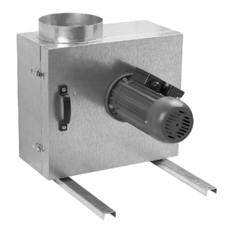
Chicago Blower Design 62 Series User manual

SAFETY - INSTALLATION - OPERATING
AND MAINTENANCE INSTRUCTIONS
Bulletin IMI - FK 6/11
1675 LEN ELLYN ROAD • LENDALE HEI HTS, IL 60139
PHONE: 630/858-2600 • FAX: 630/858-7172
www.chicagoblower.com • E-mail: fans@chicagoblower.com
FAN KIT COMPONENTS
RECEI ING:
Chicago Blower Corporation equipment is prepared for shipment in
accordance with the Uniform Freight Classification. It is thoroughly
inspected at the factory and, barring damage in transit, should be in
good condition upon arrival.
When a carrier signs Chicago Blower Corporation's bill of lading, the
carrier accepts the responsibility for any subsequent shortages or dam-
age evident or concealed, and the purchaser must make any claim
against the carrier. Evident shortage or damage should be noted on the
carrier's delivery document before signature of acceptance. Inspection
by the carrier of damage evident or concealed must be requested. After
inspection, issue a purchase order for necessary replacement parts or
arrange with the Chicago Blower Corporation service department for
return of the equipment to the factory for repair.
HANDLING:
Chicago Blower components are shipped boxed or skidded and should
be handled and moved using good rigging techniques, being careful to
avoid concentrated forces that distort or bend any of the parts. Partial
or disassembled units require special handling. All parts should be handled
in a manner which protects the parts and their coating from damage.
If the shaft and wheel is shipped as an assembly it can be lifted using
a hoist and a spreader with a sling around shaft at points nearest the
wheel. Take special care not to scratch the shaft where the bearings or
wheel will be mounted. Never lift the wheel/shaft assembly by the
wheel. Always support the assembly by the shaft when lifting or storing.
Do not support the shaft or wheel on the housing sides. Use only the
key provided with the shaft and wheel.
Slings running through the blades and around the hub can lift wheels
shipped separately. Never lift the wheel by blades of flanges alone.
Always transport wheels by lifting. Do not roll the wheel as this can
damage coatings and affect the balance of the wheel.
Bent shafting can be a source of vibration and bearing failure, so han-
dle the shaft with care.
STORAGE:
If the fan kit installation is to be delayed, store the parts in a dry pro-
tected area. Protect the parts, especially the kit and motor bearings,
from moisture and vibration. Protect all machined surfaces such as the
bore of a wheel hub, bushings, shafts, and couplings. Keep the bear-
ings fully greased by filling monthly with a grease compatible to that
originally supplied. Contact Chicago Blower for extended storage
instructions.
an ISO 9001 Company
Design 62 – Design 41
Design 1900 Series PFD
•WHEELS
•INLET CONES
•HOUSINGS
•SHAFTS
•INLET OLUME CONTROL DAMPER
•BEARINGS
•COOLING WHEELS

SAFETY PRECAUTIONS:
The fan kit, which you have purchased, is a rotating piece of equipment
and can become a source of danger to life or cause injury if not properly
applied. The maximum operating temperature or speed for which this fan
is designed must not be exceeded. These limits are given in our catalog
or on Chicago Blower Corporation drawings.
Personnel who will operate these fan kits, or those who will perform main-
tenance thereon, must be given this manual to read and warned of the
potential hazards of this equipment.
This bulletin contains general recommendations, but specific require-
ments may apply to given installation. Such requirements are outlined in
federal, state and local safety codes. Strict compliance with these codes,
and strict adherence to these installation instructions are the responsibil-
ity of the user.
HOUSINGS:
Housing stiffeners or frame should provide rigidity and support to the
housing. Housings are often supplied less stiffeners to provide flexibility
for various installations. See Fan Kit Bulletins –SAF (single width), -DAF
(double width), or –PFD as required for recommended bracing schedule.
Additional support may also be required. Supports should not restrict air
flow to the inlet or discharge of the fa
WHEEL DESIGN NOTE:
Many airfoil wheels supplied by Chicago Blower have weep holes sup-
plied as standard. The weep holes are small diameter holes located on
the top skin of the blade near the trailing edge or integrally formed into
the blade. Weep holes are designed to allow condensation, which can
accumulate within an airfoil blade when at rest, to be expelled when the
wheel is running. When the wheel is running centrifugal forces of the
rotating wheel force the condensation out the weep hole. Without the
weep holes the condensation can adversely affect the balance integrity of
the wheel. This condensation phenomenon typically occurs in applica-
tions where the system conditions i.e. temperature or density varies from
that of the ambient surroundings. If high humidity is involved in your appli-
cation contact Chicago Blower for recommendations.
BALANCE:
All Chicago Blower wheels are precision balanced at the factory to ISO
1940/ANSI S2.19 Quality rade 6.3 or better; however, when a preci-
sion balanced wheel is installed onto a shaft, there are many other
aspects to consider before the system will run with minimal vibration.
Some of these include, but are not limited to, fit-up the wheel hub to the
shaft, especially if bushings are used, residual imbalance of a motor,
residual imbalance of the sheaves used for belt drive, soft foot on the
motor caused by improper shimming of the fan bearings, alignment of the
shaft coupling, and alignment of the fan bearings. With all of these items
playing a part in the overall vibration of the assembly, it may seem daunt-
ing to commission a system with low vibration and minimal maintenance
that will operate for years.
To minimize system vibration the wheel must be “phase balanced” to the
rest of the components in the rotating system. What is phase balance?
Phase balance is performing a touch up or trim balance to any compo-
nent of the rotating system including the wheel. Depending on whether
the wheel or other rotating component has one or two planes, phase bal-
ance can be carried out in either single plane or two plane mode. Also,
a phase balance does not mean that the wheel itself is out of balance;
rather, phase balance of an otherwise perfectly balanced wheel is usual-
ly easiest because it is typically the largest and heaviest rotating element
of the system. It is easier to apply the correction weights to the outer
diameter of the wheel to compensate for the imbalance of the rotating
system. There are times where the imbalance of the system is minimal
and no phase balance is required for smooth operation.
Once the wheel has been phase balanced to the rotating system, the
wheel must be visually inspected periodically for any signs of wear or
material build up that can cause imbalance. In material handling sys-
tems, even a small amount of material that has eroded or corroded the
wheel can affect the balance of that wheel. If this were to happen, the
wheel would have to be phase balanced to the rotating system again to
correct the balance for the missing material. Eventually, eroded or cor-
roded wheels will not be able to be rebalanced and will need to be
replaced entirely to avoid total failure. In addition, rotating systems that
handle clean air can also have eventual balance problems if not
watched closely. Fine dirt and dust can build up on the wheel blades
causing imbalance again. Occasionally, the wheel must be cleaned to
restore the balance.
It is also recommended that vibration checks be conducted on the fan
and motor bearings. Fans that have been tested for vibration with
phase balanced wheels normally run smoothly at first and over time
begin to show signs of increasing vibration levels. Steadily increasing
vibration levels are indicators that the wheel or other rotating element
has gone out of balance for the reasons stated above, or the bearings
have begun to wear and will need to be replaced.
FAN KIT ASSEMBLY and INSTALLATION:
Fan Kit components are available separately or in virtually any combi-
nation including wheel, inlet cone, inlet volume control damper, hous-
ing, shaft, bearings and cooling wheel. Housings are to be mounted so
the inlets are free from obstructions and should be centered within
enclosures for double inlet fans. Bearing pedestals are to be installed
so that the bearings can be shimmed for proper centerline height.
If mounting within an oven or enclosure, provide an opening in the wall
for shaft to pass through. Additional space at wall may be required
when installing a cooling wheel and cone. Installation of a cooler cone
may also require the use of a cylindrical section to retain insulation and
maintain proper depth of over wall.
2
1. Move components to the final mounting location. Be sure to follow
the handling instructions given above.
2. Remove skid, crates, and packaging.
3. Move lower housing/supports to mounting location.
4. Level and shim if required. Do not distort or twist the equipment. Bolt
into place.
5. If bearing support is separate from housing:
a. Set bearing pedestal on bolts.
b. Never distort bearing pedestal by forcing into position espcially if
mounting to a non-level surface. Shim under pedestal as required.
c. Check bearing centerline height. Adjust centerline height to
match centerline of housing. High temperature applications may
require the housing centerline to set lower when cold so that
it will be centered when hot due to thermal expansion.
d. Measure from housing to bearing pedestal to bring into square
with housing.
e. Bolt into position.
6. Shaft and wheel assembly
a. Clean protective coating off shaft with solvent. Do not touch clean
areas of shaft with hands. Perspiration or oils from hands can
cause rust or pitting over time.
b. Remove keys from shaft.
c. Clean inside of bore. Bores may have paint overspray and dirt
from shipment which must be removed prior to mounting the
wheel and/or bushing. Make sure hub set screws or bushing
mounting bolts are loosened as to not interfere when inserting
shaft into bore.
7. Continue to 8, 9 or 10 based on arrangement.
8. Arrangements 1, 8 or 9
a. Insert shaft into wheel from back side of wheel.
b. Typically shaft should protrude out face of hub approximately 1-1/2".
Put key into keyway and lightly tighten wheel set screws. Do not
torque set screws at this time.
c. Install bearings onto shaft. Do not tighten bearing set screws at

THREADED HOLES
USED FOR REMOVIN
BUSHIN
TAPER-LOCK
BUSHING DETAIL
3
A. Assembly
Check bushing to verify type or refer to the bushing box shipped
with the wheel.
To reinstall the taper-lock bushing in the wheel hub, clean bushing,
hub and shaft of all oil, lacquer, grease or dirt. Orient bushing to
align the match marks and insert the three mounting bolts through
the unthreaded bushing holes into the hub. Alternately tighten the
bolts. Do not use oil or other lubricants in bushing or hub.
When tightening, the bolts should be turned down equally to the
Initial Torque requirement given below. Then tighten the bolts pro-
gressively to the Second Torque setting. Finally, the bolts should be
tightened in small increments to the Final Torque settings below.
Figure 1A Figure 1B
SET SCREW TORQUE ALUES
B. Disassembly
1. Match mark the bushing and the hub so they can be reinstalled in
exactly the same relative position to insure the balance integrity of
the wheel.
2. Remove all bolts from the bushing.
3. Insert two bolts in the threaded holes in the bushing. See bushing/
wheel detail in Figure 2b. (Note that one bolt is left over and not
used in demounting.)
4. Tighten bolts alternately until bushing is loosened in hub. If the
bushing does not loosen immediately, lightly tap hub while apply-
ing torque to the bolts.
5. See Step A. above for assembly.
Straight Bore Assembly
Tighten all set screws over the
keyway first, then tighten all set
screws which are located 90°
to 120° from the keyway. Torque
all set screws per the chart.
Bushed Bore Assembly
Changing of the busing can ad-
versely affect the balance of a
wheel. If the bushing is changed
for any reason be sure to recheck
balance of the wheel prior to
putting the unit back into service.
Figure 2
WHEEL and INLET
CONE O ERLAP
ALUES
1/4
5/16
3/8
7/16
1/2
5/8
3/4
20
18
16
14
13
11
10
65.5
136.0
239.0
381.0
586.0
1163.0
2076.0
Bolt
Size
(In. Dia.)
Threads
Per
Inch
Steel Grade 2
Non-Plated
(Inch-lbs.)
Q&R
P
57
36
120
84
108
72
240
132
228
132
Size
Bushing Alum. Steel Alum. Steel
Initial Torque* Second Torque*
348
192
Alum. Steel
Final Torque*
* Torque values shown are inch lbs. and apply when both components are
either aluminum or steel. If either component is aluminum, use values for
aluminum. Values for steel are for rade 5 hardware.
this time. The bearing housing should be perpendicular and the
bearing base parallel to the axis of the shaft to prevent misalign-
ment loads. Continue to Step 11.
d. Bolt bearings to pedestals. Shaft must be parallel with side of
bearing pedestal.
9. Arrangement 3
a. Parts on DIDW unit are assembled in the following order as
viewed from opposite drive side: Opposite inlet cone, bearing bar
assembly and opposite bearing (housing side),wheel/shaft (hous-
ing side), drive inlet cone, drive side bearing bar assembly, drive
bearing and sheaves. Mount bearing bar assembly to housing.
Center the wheel in inlet cones axially and maintain equal radial
clearance between wheel and cones.
b. Parts on SISW are assembled in the following order as viewed
from opposite drive side: Bearing bar assembly and opposite
bearing (inlet housing side), wheel/shaft (drive housing side),
inlet cone, drive side bearing bar assembly, drive bearing and
sheaves. Mount bearing bar assembly to housing. Continue to
step 11.
c. Bolt bearings to pedestals. Shaft must be parallel with side of
bearing pedestal.
10. Arrangement 4
a. Mount and loosely bolt motor on pedestal or structure. Mount
wheel on shaft loosely and install inlet cone. Continue to step 12.
11. After aligning and bolting to pedestal, tighten bearing set screws.
Make sure bearing locking collar is in position and set screws are
tightened to the bearing manufacturer's recommended torque
levels indicated by the manufacturer, but recheck. If grease is re-
quired, use the grease recommended in bearing instruction manual.
12. Identify the wheel as a straight bore or a bushed bore. See Figure
1 showing both straight and bushed hub types. Position wheel on
shaft to properly set the wheel to cone fit (see Figure 2, Wheel to
Inlet Cone Overlap). A special non-standard gap may be required
for high temperature applications; refer to factory for proper high-
temp setting.
13. Tighten/torque all remaining hardware at this time.
14. Check the motor wiring and fusing in accordance with the National
Electrical Code and local requirements. Follow wiring diagram on
the motor nameplates or conduit boxes.
15. Check motor bearing lubrication. Motors were lubricated by the
manufacturer, but recheck. If grease is required, use the grease
recommended in the motor instruction manual.
STRAIGHT BORE HUB DETAIL

1675 LEN ELLYN ROAD • LENDALE HEI HTS, IL 60139
PHONE: 630/858-2600 • FAX: 630/858-7172
www.chicagoblower.com • E-mail: fans@chicagoblower.com
8. The run-in period should be at least eight hours. Check bearings a
minimum of once each hour during this period. Overgreasing may
cause bearings to heat up. There need be no concern if the bare hand
can be held on the bearings briefly. Bearings will vent extra grease and
cool down after start-up. Recheck torque of all bearing set screws after
eight and twenty-four hours of operation to insure levels are maintained
per the bearing manufacturer's recommended levels.
9. Take vibration readings at the bearings, or the motor bearings if the
fan wheel is mounted directly on the motor shaft. Adhere to these lim-
its. Velocity Limits in inches/second filter in – Normal: 0.15; Alarm: 0.22,
Shutdown: 0.50.
MAINTENANCE:
To insure long life and trouble-free service, frequently check all bearing
lubrication. See the bearing manufacturer's instructions packed with the
fan. Should excessive vibration develop, check the following possibili-
ties:
1. Build-up of dirt or foreign material on the wheel.
2. Loose bolts on bearings, housings, foundation and drive.
3. V-belt drives improperly aligned. Belts must have proper tension,
sheaves must be balanced.
4. Check wheel set screws
5. Foreign matter may have entered fan causing damage to wheel, shaft
or bearings.
6. Vibration may be coming from a source other than the fan. Stop the
fan and determine if the vibration still exists. Disconnect driver from
the fan and operate it by itself to determine if it produces vibration.
7. Proper clearance between the wheel and the inlet.
A preventive maintenance schedule is a necessity for extending fan life.
Establish a lubrication schedule based on time periods suggested in
lubrication instructions and by motor and bearing manufacturers.
After approximately one (1) month of operation, all base, hub, bearing,
pedestal, etc. bolts should be checked.
Potentially damaging conditions are often signaled in advance by
change in vibration and sound. A simple, regular audio-visual inspec-
tion of fan operation leads to correction of the condition before expen-
sive damage occurs. Vibration levels should be checked by an
approved technician using electronic balancing equipment.
If air handled by the fan contains corrosive, erosive or sticky materials,
fan should be shut down regularly for inspection, cleaning and recondi-
tioning of interior parts.
If the fan is to remain idle for an extended period, fill bearing with
grease. Protect motor and exposed surfaces. Follow the motor manu-
facturer's recommendations for storage and rotate the shaft by hand
several revolutions each month.
Mechanical Integrity: Certain operating conditions reduce the built-in
strength in the fan impeller and may cause unsafe operation. It is the
user's responsibility to inspect for these conditions as frequently as
necessary and to make corrections as required. Failure to comply with
the following limits voids the Chicago Blower Corporation warranty.
Maximum Safe Speed and Temperature: Operation exceeding maxi-
mum safe RPM and temperarture even for a short time causes over-
stressing or fatique cracking of the impeller, resulting in unsafe condi-
tion. Maximum safe speed and maximum safe temprature are shown
on fan assembly drawings, catalogs or order acknowledgement.
Warranty: The warranty on Chicago Blower fans is our standard warranty.
The warranty on the motor is that extended by the motor manufacturer.
FAN BEARINGS:
1. Lubricate fan bearings per instructions in packet attached to the fan.
Use a premium quality NL #1 or 2 grade multi-purpose grease, such
as Shell Alvania rease 2. Lubricate bearings immediately on receipt.
Add enough grease to cause slight purge at seals. It is common for
bearings to purge excessive grease during first 24 to 48 hours of oper-
ation. See bearing manufacturer's instructions enclosed for lubrication
schedule.
2. Bearing must be properly locked to the shaft. Check before operation.
Make sure bearing locking collar is in position and set screws are tight-
ened to the bearing manufacturer's recommended torque levels. See
bearing manufacturer's instructions enclosed for details. The bearing
set screws should be re-torqued after eight and twenty-four hours of
operation.
3. ertical Operation: If the fan is to operate with its shaft vertical,
reset the fan bearings as follows:
a. With the shaft vertical, unlock the drive end bearing set screws and
turn the shaft by hand. This allows the wheel end bearing to take
the gravity load of the shaft and wheel.
b. Re-lock the drive end bearing locking device and replace and
torque set screws as required by the bearing manufacturer's
instructions so that this bearing now takes only the belt pull.
4. Do not use "high temp" greases. Many are not formulated for the high
speeds associated with fan bearings.
HOUSINGS:
Housing stiffeners or frame should provide rigidity and support to the
housing. Housings are often supplied less stiffeners to provide flexibili-
ty for various installations. See Fan Kit Bulletins –SAF (single width), -
DAF (double width), or –PFD as required for recommended bracing
schedule. Additional support may also be required. Supports should not
restrict air flow to the inlet or discharge of the fan.
OPERATION of FAN:
After installing the fan per these instructions and the instructions of the
manufacturers, make final safety checks to prevent injury to personnel
or damage to the equipment. Always block rotating parts to prevent
windmilling while inspecting the fan.
1. Lock power source in "OFF" position.
2. Check bearings for alignment and proper lubrication, with wheel and
inside of the housing clean and free of debris.
3. Check wheel position for proper clearance and rotation. Unblock
rotating parts and turn wheel by hand to insure that it rotates freely.
4. Check wheel set screws or bushing for tightness. If fan will see high
temperatures, check to see that the shaft cooling wheel bolts are tight.
Check foundation bolts. Secure safety guards and access doors.
5. Start fan and allow unit to reach full speed, then shut down. During
this short period, check for rotation, excessive vibration, any unusual
noise, or overheating of the motor. Check the motor amps drawn
against the nameplate rating. A plate over the fan inlet will limit the
horsepower drawn during a test run with limited ductwork.
6. After the trail run lock the power "OFF".
7. Recheck for tightness of hold-down bolts, wheel set screws andkeys,
and retighten if necessary. Recheck after eight and twenty-four hours of
operation.
an ISO 9001 Company
This manual suits for next models
2
