Lasko 4820 Parts list manual

Rev. A 11/04 1 4820ES
MODELO 4820
Rev. A 11/04 84820ES
SI NECESITA PIEZAS ADICIONALES FAVOR DE COMUNICARSE CON EL FABRICANTE POR LA GARANTIA DEL REMPLAZO DE
PIEZAS. INCLUYA UNA COPIA DE LA PRUEBA DE COMPRA, EL TIPO Y ESTILO DEL VENTILADOR, ESTA INFORMACION PUEDE
LOCALIZARLA EN LA PARTE DE ABAJO DE LA UNIDAD.
ESTEPRODUCTOESTAGARANTIZADOCONTRADEFECTOSDEFABRICACIONY/OMATERIALSPORUNAÑOAPARTIRDELAFECHA
DECOMPRA.ANUESTRAOPCION, PIEZASQUESE COMPRUEBENQUEESTEN DEFECTUOSASSERANREPARADAS. REMPLAZADAS
O SE REMPLAZARA EL PRODUCTO POR COMPLETO.
SI NECESITA REPARACIONES ELECTRICAS O MECANICAS DURANTE EL PERIODO DE GARANTIA, ENVIE LA UNIDAD POR CORREO
O FLETE PAGADO AL CENTRO DE SERVICIO MAS CERCANO, LISTADO EN ESTA TARJETA.
SI SOLAMENTE NECESITA REMPLAZAR UNA PIEZA, TIENE QUE INDICAR EL TIPO Y ESTILO DEL VENTILADOR, ESTA INFORMACION SE
ENCUENTRA EN LA PARTE DE ABAJO DE LA UNIDAD. DE CUALQUIER FORMA, SE SOLICITA UNA COPIA DE LA PRUEBA DE COMPRA.
ESTAGARANTIA NO ESVALIDASI EL DANOOCURREDEBIDO A UNACCIDENTE,MANEJO, INSTALACION, OPERSCIONINCORRECTA,
DANO DURANTE EL TRANSPORTE, MALTRATO, USO INDEBIDO, REPARACIONES HECHAS O INTENTADAS NO AUTHORIZADAS, O EL
USO DEL PRODUCTO PARA FINES COMERCIALES.
TODAS LAS GARANTIAS EXPRESAS O IMPLICITAS, TIENEN UNA DURACION DE UN ANO A PARTIR DE LA FECHA DE COMPRA
ORIGINAL. ESTA GARANTIA EXPRESAS O IMPLICITAS, TIENEN UNA DURACION DE UN ANO A PARTIR DE LA FECHA DE COMPRA
ORIGINAL. ESTA GARANTIA NO CUBRE RESPONSABILIDADES POR DANOS PORTUITOS O CONSECUENTES POR NINGUNA CAUSA.
DADO QUE ALGUNOS ESTADOS NO PERMITEN NINGUNA LIMITACION EN LA DURACION DE UNA GARANTIA IMPLICADA, O LA
EXCLUSION O RESTRICCION DE DANOS FORTUITOS O CONSECUENTES. LA LIMITACION O EXCLUSION ANTES MENCIONADA
PODRIA SER NO VALIDA. ESTA GARANTIA EXTIENDE AL COMPRADOR ORIGINAL DERECHOS LEGALES ESPECIFICOS Y USTED
PODRIA TENER OTROS DERECHOS, LOS CUALES VARIAN DE UN ESTADO A OTRO.
GARANTIA LIMITADA - NO ES VÁLIDA EN MÉXICO
PARA PIEZAS:
Para Repuestos Llame al: 1-800-233-0268. DE LUNES A VIERNES, DESDE LAS 8 DE LA MAÑANA A LAS 4 DE LA
TARDE, HORA DEL ESTE. "POR FAVOR NO DEVUELVA EL PRODUCTO AL SITIO DONDE LO COMPRÓ". Cuando
llame, refiérasa al tipo y estilo del producto (situados en la base del producto).
PARA OBTENER ASISTENCIA TÉCNICA Y LAS DIRECCIONES DEL CENTRO DE SERVICIO:
Para cualquier pregunta, comentarios o para obtener la dirección de su centro de servicio más cercano, SÍRVASE
LLAMAR A NUESTRO "TELÉFONO DE EMERGENCIA" GRATUITO AL 1-800-233-0268, DE LUNES A VIERNES,
DESDE LAS 8 DE LA MAÑANA A LAS 4 DE LA TARDE, HORA DEL ESTE. Cuando llame, refiérasa al nombre y número
de modelo del producto
Departamento de Servicio para Equipos • 300 Confederate Drive Franklin, TN 37064
¡POR FAVOR, NO ENVÍE EL PRODUCTO A ESTA DIRECCIÓN!
Para más información, por favor visite nuestro sitio web: www.laskoproducts.com
NOTAS
48” XTRA AIR TOWER FAN with IONIZER
and REMOTE CONTROL
MODEL 4820
1. Read all instructions before using Fan.
2. Make certain that the power source conforms to the electrical
requirements of the Fan.
3. Use this Fan only as described in this manual. Any other use
notrecommended by the manufacturermaycause fire,electrical
shock, or injury to persons.
4. To reduce the risk of personal injury and electric shock, the Fan
should not be played with or placed where small children can
reach it.
5. Unplug power cord before installing, servicing, or moving the
Fan.
WARNING: DO NOT DEPEND UPON THE ON-OFF
SWITCH AS THE SOLE MEANS OF DISCONNECTING
POWER WHEN INSTALLING OR SERVICING THE FAN.
ALWAYS UNPLUG THE POWER CORD.
6. This Fan must NOT be used in potentially dangerous
locations such as flammable, explosive, chemical-laden
or wet atmospheres.
7. DO NOT use Fan in ornear a window. Rain may create an
electrical hazard.
8. Completely reassemble Fan, according to instructions, be-
fore reconnecting to power supply.
WARNING: THIS APPLIANCE HAS A POLARIZED PLUG
(ONE BLADE ISWIDERTHANTHE OTHER). TO REDUCE
THE RISK OF ELECTRIC SHOCK, THIS PLUG IS
INTENDEDTO FIT IN A POLARIZED OUTLET ONLY ONE
WAY. MATCH WIDE BLADE OF PLUG TO WIDE SLOT,
FULLY INSERT. IF THE PLUG DOES NOT FIT FULLY IN
THE OUTLET, REVERSE THE PLUG. IF IT STILL DOES
NOT FIT, CONTACT A QUALIFIED ELECTRICIAN. DO
NOT ATTEMPTTO DEFEATTHIS SAFETY FEATURE.
WARNING: THIS PLUG IS A SAFETY FEATURE. TO
REDUCE THE RISK OF FIRE, ELECTRIC SHOCK AND
PERSONAL INJURY, DO NOT REMOVE, REPLACE,
REPAIR OR TAMPER WITHTHE ORIGINALLY SUPPLIED
PLUG. IFTHE FAN DOES NOT FUNCTION PROPERLY, IT
MAY BE DUETOTHE SAFETY DEVICE INCORPORATED
IN THIS PLUG. RETURN TO AN AUTHORIZED SERVICE
CENTER OR CALL 800-233-0268, MONDAY - FRIDAY,
BETWEEN 8:30 AM AND 4:00 PM EST. IF THE PLUG
WARNING LABEL IS MISSING OR DAMAGED, CALLTHE
TOLL FREE NUMBER FOR A REPLACEMENT LABEL.
9. Where possible, avoid the use of extension cords. If they must be
used, minimize the risk of overheating by ensuring that they are
UL listed. Never use a single extension cord to operate more
than one Fan.
10.Do not operate any Fan with a damaged cord or plug or after the
Fan malfunctions, has been dropped or damaged in any manner.
Return Fanto authorizedservice facilityforexamination, electrical
or mechanical adjustment or repair.
11.Do not insert or allow fingers or foreign objects to enter any
ventilation or exhaust opening as it may cause an electric shock
or fire, or damage the Fan. Do not block or tamper with the Fan
in any manner while it is in operation.
12.Always place the Fan on a stable, flat, level surface when
operating, to avoid the chance of the Fan overturning. Locate
the Power Cord so the Fan or other objects are not resting on it.
Do not run Power Cord under carpeting. Do not cover Power
Cord with throw rugs, runners, or the like. Arrange Power Cord
away from room traffic and where it will not be tripped over.
13.This Fan is not intended for use in wet or damp locations.
Never locate a Fan where it may fall into a bathtub or other
water container.
14. Do not use Fan outdoors.
WARNING: REDUCETHE RISK OF FIRE OR ELECTRIC
SHOCK – DO NOT USETHIS FAN WITH ANY SOLID STATE
SPEED CONTROL DEVICES.
This Fan is for residential use only.
It is not intended to be used in commercial or industrial settings.
GENERAL SAFETY INFORMATION
When using electrical appliances,
basic precautions should always be followed
to reduce the risk of fire, electric shock and injury to persons,
including the following:
READ AND SAVE THESE INSTRUCTIONS
READ CAREFULLY BEFORE ATTEMPTING TO ASSEMBLE, INSTALL, OPERATE OR MAINTAIN THE PRODUCT DESCRIBED.
PROTECT YOURSELF AND OTHERS BY OBSERVING ALL SAFETY INFORMATION. FAILURE TO COMPLY WITH
INSTRUCTIONS COULD RESULT IN PERSONAL INJURY AND/OR PROPERTY DAMAGE!
RETAIN INSTRUCTIONS FOR FUTURE REFERENCE.
IMPORTANT INSTRUCTIONS -
OPERATING MANUAL
SAVE THESE INSTRUCTIONS
Meijer.com

Rev. A 11/04 74820ESRev. A 11/04 24820ES
MODEL 4820
MANTENIMIENTO
ADVERTENCIA:SIEMPRE DESCONECTE EL ENCHUFE
ANTES DE MOVER O PROPORCIONAR SERVICIO AL
VENTILADOR.
ADVERTENCIA: ¡NO SUMERJA ELVENTILADOR EN AGUA!
LIMPIEZA: Limpie el Ventilador con un aditamento de cepillo que
se ajuste a su máquina aspiradora. Esto eliminará la suciedad y el
polvoque sepuedenacumularcon el paso del tiempo.NO INTENTE
DESARMAR ELVENTILADOR. Limpie el cuerpo del Ventilador con
un paño suave.
ADVERTENCIA: No use gasolina, bencina, acetona,
limpiadores abrasivos,etc., puesto que eso dañará elVentilador,
NUNCA use ALCOHOL o SOLVENTES.
SERVICIO: Cualquier otro servicio, con la excepción de
mantenimiento general por parte del usuario, deberá ser realizado
por un representante de servicio autorizado. Llamar al 1-800 -233-
0268, de lunes a viernes, entre las 8 a.m. y las 5 p.m. (Horario
Estándardel Este de los Estados Unidos), para averiguar la dirección
de su centro de servicio más cercano.
ALMACENAMIENTO: Guarde elVentilador,con estasinstrucciones,
en un lugar fresco y seco.
MODELO 4820
ASSEMBLY
1. For ease of assembly, lay the Fan down so that the front grill and
control panel are facing up.
2. Assemblethe Support BaseHalves by interlocking the Bosses on
SupportBase AintotheBoss Holeson SupportBase B. Thread
thePower Supply Cord through the large hole in the center of the
Support Base Assembly
.
(Figure 1)
CONTROL REMOTO
(Figuras 5 y 6)
1. Instale las dos baterías “AAA” que vienen con el equipo, como
se indica en la
Figura 5
.
2. El Botón De Encendido del Control Remoto está
identificado como ( ).
3. Todas las funciones realizadas con el Control Remoto pueden
realizarse de igual forma con los Controles Manuales.
4. Remote control hook is located on back of Fan. Spanish
Translation is Needed.
3. Secure (2) #8 X 1/2” Screws into the two outer holes in the
bottom of the
Base.
(Figure 2)
Support Base
Assembly
Figure 2
Power
Supply Cord
#8 X 1/2” Screws
Power Supply
Cord
Support
Base A
Support
Base B
Bosses
Figure 1
FUNCIONAMIENTO
EsteVentiladorpodráhacerse funcionarmediantelos controlesmanuales
ubicados en la parte superior de la unidad (como se indica en la
Figura
4
) o con el Control Remoto (como se indica en la
Figura 5
)
1. Retire el ventilador de su caja y reúna como instruido.
2. Coloque el Ventilador sobre una superficie firme y plana.
ADVERTENCIA: Las etiquetas del plástico o el caucho, quieren los
pies en esta unidad, pueden atascar a pisos de madera dura. La
unidad puede salir un residuo que podría oscurecer, poder manchar
o podría salir imperfecciones permanentes en el fin de ciertos pisos
de madera dura.
3. Cerciórese de que el enchufe encaje bien en el tomacorriente de 120V.
4. Encienda el Ventilador oprimiendo el
Botón de Encendido
( ).
Se iluminará una luz verde cuando se encienda el Ventilador.
Esta luz permanecerá encendida hasta que se apague la
unidad. La unidad funcionará a velocidad baja cuando la
encienda por primera vez.
5. VELOCIDADES: Oprima el
Botón de Velocidad
de Ventilador
() para ajustar la velocidad deseada. Cada vez que oprima el
Botón de Velocidad de ventilador, la velocidad cambiará de baja
(1), a mediana (2) a alta (3).
6. OSCILACIÓN: Oprima el
Botón de Oscilación
( ) para iniciar
y detener la función oscilante.
7. TEMPORIZADOR: La función temporizadora permite ajustar la
unidad para que funcione durante un lapso que va desde 1/2
hora hasta 7 1/2 horas, en incrementos de 1/2 hora. Oprima el
Botón Temporizador
( ) para ajustar el lapso de tiempo de su
preferencia.Cadavez que oprimael botón temporizador,eltiempo
aumentará en 1/2 hora.Al llegar a 7 1/2 horas, si oprime el botón
temporizador una vez más, el Ventilador se reajustará al modo
de funcionamiento continuo. Las luces en la parte frontal de la
unidad se encenderán para indicar el tiempo durante el cual el
Ventilador estará funcionando.
8. IONIZANTE: La Función Ionizante de este Ventilador funcionará
con cualquier modo de velocidad.Oprima el
Botón de Ionizante
(
I
N
) una vez para activar esta función y una segunda vez para
desactivarla.El Ventilador deberá estar ENCENDIDO para que el
Ionizante pueda funcionar. Cuando el Ionizante se encuentra
activado, esto ayudará a purificar el aire de la habitación,.
9. Para APAGAR el Ventilador, oprima el
Botón de Encendido/
Apagado
() y desenchufe la unidad del tomacorriente.
Si usted pierde su mando a distancia, por favor Cliente de llamada
Serive para ordenar un reaplacement en 1-800 -233-0268, de lunes
a viernes, entre las 8 a.m. y las 5 p.m. (Horario Estándar del Este de
los Estados Unidos).
Botón de Encendido/Apagado
Botón de
Ionizante
Botón
Temporizador Botón de
Velocidad
Botón de
Oscilación
Figura 4
4. AligntheSupportBaseAssembly withtheMotorBase,noting
that the cord channel on the bottom of the support base
assembly should be towards the back of the Fan. . Attach the
SupportBase Assemblyto theMotor Base with(4) 1/2”Long
M5Screws. Makecertaintoalignthe
Key
onthe
SupportBase
Assembly
with the
Locating Notch
on the
Motor Base.
(Figure 1)
Gently pull any excess slack of the Power Supply
Cord and place it in the Wire Locating Trough.
(Figure 3)
Key
Power Supply
Cord
Wire
Locating
Trough
1/2” Long
M5 Screws
Support Base
Assembly
Motor Base
Figure 3
Figura 5
Espalda De
Telemando
Vista Frontal
del Control
Remoto
Figura 6
Side View of Fan
Meijer.com

MODEL 2535
Rev. A 11/04 34820ES
Rev. A 11/04 64820ES
MODEL 4820
MODELO 4820
REMOTE CONTROL
(Figures 5 and 6)
1. Install the two “AAA” batteries supplied as shown in
Figure 5
.
2. The Remote Control Power Button is labeled as ( ).
3. All the functions performed with the Remote Control work identi-
cally to the Manual Controls.
4. Remote control hook is located on back of Fan.
(Figure 6)
Figure 4
Fan Speed
Button
Oscillation
Button
Timer
Button
Ionizer
Button
Power Button
OPERATION
This Fan may be operated by the manual controls located on
top of the unit (as shown in
Figure 4
) or by the Remote Control
(shown in
Figure 5)
.
1. Remove the Fan from the carton and assemble as instructed.
2. Place the Fan on a firm, level surface.
WARNING: Plastic or rubber tabs, like the feet on this unit, may
stick to hardwood floors. The unit may leave a residue that could
darken, stain or leave permanent blemishes on the finish of certain
hardwood floors.
3. Plug the cord set into a 120 V~ electrical outlet. Be sure plug fits
tightly in outlet.
4. Turn the Fan on by pressing the
Power Button
( ). A light will
appear when the Fan is turned on. This light will remain lit until
the unit is turned off. The unit will be in low speed when
originally turned on.
5. SPEEDS: Press the
Fan Speed Button
( ) to desired speed
setting. Each time the Fan Speed Button is pressed, the speed
will change from low (1), to medium (2), to high (3).
6. OSCILLATION: Press the
Oscillation Button
( ) to start and
stop the oscillation function.
7. TIMER: The timer function allows the unit to be set to operate for
a length of time from 1/2 hour to 7 1/2 hours, in increments of a 1/
2 hour. Press the
Timer Button
( ) to set the length of time
desired. Each time the timer button is pressed, the time is
increased by 1/2 hour. After reaching 7 1/2 hours, pressing the
timer button once more will reset the Fan to continuous running.
The lights on the front of the unit will light up appropriately with
the length of time that the Fan is set for.
8. IONIZER: The ionizer function on this Fan will operated within
any speed mode. Press the
Ion Button
(
I
N
) once to turn this
function on and a second time to turn it off. The Fan must be ON
for the ionizer to be functional.When the ionizer is turned on it will
assist in the purification of the room air.
9. To turn the Fan OFF, press the
Power Button
() and unplug the
unit from the electrical outlet.
MAINTENANCE
WARNING: ALWAYS UNPLUG THE CORD BEFORE MOVING
OR SERVICING.
WARNING: DO NOT IMMERSE FAN IN WATER!
CLEANING: Clean the Fan with the vacuum brush attachment
on your vacuum cleaner. This will remove dirt and lint that may
accumulate over time.DO NOT ATTEMPTTOTAKE APART FAN.
Clean the body of the Fan with a soft cloth.
CAUTION: Do not use gasoline, benzine,thinner, harsh clean-
ers, etc. as they may damage the Fan. NEVER use ALCOHOL
OR SOLVENTS.
SERVICING: All other servicing, with the exception of general
user maintenance, should be performed by an authorized service
representative.Call 1-800-233-0268, Monday through Friday, be-
tween the hours of 8:00 a.m. and 5:00 p.m. EST for the location
of your nearest service center.
STORAGE: Store the Fan, with these instructions, in a cool, dry
place.
If you lose your remote control, please call Customer Service to
order a replacement at 1-800-233-0268, Monday through Friday,
between the hours of 8:00 a.m. and 5:00 p.m.EST.
ARMADO
1. Para un armado más sencillo, deposite el Ventilador hacia abajo
paraquelaparrillafrontalyelpaneldecontrolapuntenhaciaarriba.
2. Arme las Mitades de la Base de Apoyo encastrando las
Puntas
de la
Base de Apoyo A
con los Orificios para
Puntas en la Base
deApoyoB
.Conecteel
CableEléctrico
atravésdel orificiogrande
en el centro de la
Montura de la Base de Apoyo
.
(Figura 1)
3. Asegure
(2) #8 X 1/2” Tornillos
en los dos orificios externos en
la parte inferior de la
Base
.
(Figura 2)
Cable
Eléctrico
Puntas de la Base
de Apoyo A
Puntas de la Base
de Apoyo B
Puntas
Figura 1
Montura de la
Base de Apoyo
Figura 2
Cable
Eléctrico
#8 X 1/2”Tornillos
4. Alinee la
Montura de la Base de Apoyo
con la
Base del Motor
,
teniendo en cuenta que la ranura del cable en la parte inferior de la
montura de la base de apoyo debe apuntar hacia la parte posterior
del Ventilador.Adose la
Montura de la Base de Apoyo
a la
Base
del Motor
con
(4) Tornillos Largos M5 de 1/2”
. Cerciórese de
alinearla
Llave
del
Conjuntode la Base de Soporte
con la
Muesca
Localizadora
de la
Base Del Motor
.
(Figura 1)
Suavemente tire
del
Cable Eléctrico
para evitar que quede flojo y colóquelo en el
Orificio de Colocación del Cable
.
(Figura 3)
Cable
Eléctrico
Orificio de
Colocación
del Cable
Tornillos
Largos M5
de 1/2”
Montura de la
Base de Apoyo
Base del Motor
Figura 3
Llave
Figure 5
Back of
Remote
Front of
Remote
Figure 6
Side View of Fan
Meijer.com

Rev. A 11/04 44820ES Rev. A 11/04 54820ES
SHOULD ACCESSORY PARTS BE NEEDED, CONTACT THE MANUFACTURER FOR IN-WARRANTY REPLACEMENT PARTS. A
COPY OF PROOF-OF-PURCHASE MUST BE INCLUDED ALONG WITH THE TYPE AND STYLE, WHICH IS LOCATED ON THE
BOTTOM OF YOUR APPLIANCE.
Thisproduct iswarrantedfor one yearfromthe dateoforiginal purchaseagainstdefectsin workmanshipand/ormaterials. Atouroption, parts
that prove to be defective will either be repaired or replaced or the whole product will be replaced.
Shouldelectrical ormechanical repairbecomenecessary duringthe warrantyperiod,send yourcomplete product,postageor freightpre-paid
to the nearest service center. Call the number below for the service station nearest you.
Should a part need replacement, you must give us the type and style of your appliance. You will find this at the bottom of the appliance. In
either case, a copy of your proof of purchase is requested.
This warranty does not apply if the damage occurs because of accident, improper handling or operation, shipping damage, abuse, misuse,
unauthorized repairs made or attempted, or the use of the product for commercial service.
ALL WARRANTIES, EXPRESSED OR IMPLIED, LAST FOR ONE YEAR FROM THE DATE OF ORIGINAL PURCHASE. THIS
WARRANTYDOES NOT COVERLIABILITY FORINCIDENTAL ORCONSEQUENTIAL DAMAGESFORANY CAUSEWHATSOEVER.
Some states do not allow limitations on how long any implied warranty lasts, or the exclusion or limitation of incidental or consequential
damages,sothattheabovelimitationsandexclusionsmaynotapplytoyou.Thiswarrantygivesyou specific legal rights. You may also have
other rights which vary from state to state.
LIMITED WARRANTY - NOT VALID IN MEXICO
FOR PARTS:
For Replacement Parts please call: 1-800-233-0268. MONDAY THROUGH FRIDAY, BETWEEN THE HOURS OF 8
AM AND 4 PM EST. "PLEASE DO NOT RETURN PRODUCT TO PLACE OF PURCHASE." Reference the type and
style of product (located on the underside of the product) when you call.
FOR TECHNICAL ASSISTANCE and SERVICE CENTER LOCATIONS:
For any questions, comments or the location of your nearest service center, PLEASE CALL OUR TOLL-FREE
"HOTLINE" AT 1-800-233-0268. MONDAY THROUGH FRIDAY, BETWEEN THE HOURS OF 8 AM AND 5 PM EST.
Please reference product name and model no. when you call.
Appliance Service Dept. • 300 Confederate Drive Franklin, TN 37064 PLEASE DO NOT SEND PRODUCT TO THIS LOCATION!
For more information please visit our website: www.laskoproducts.com
INSTRUCCIONES IMPORTANTES - MANUAL DE USO
NOTES
MODEL 4820
1. Lea todas las instrucciones antes de utilizar el Ventilador.
2. Cerciórese de que la fuente de poder sea compatible con las
demandas eléctricas del Ventilador.
3. Use esteVentilador sólo en la forma que se describe en el manual.
Cualquier otro uso no recomendado por el fabricante podría
ocasionarun incendio,golpesde electricidadolesiones a personas.
4. Para disminuir el riesgo de lesiones físicas y golpes de
electricidad, no debe jugarse con el ventilador no deberá éste
ser ubicado al alcance de los niños pequeños.
5. Desenchufe el cable eléctrico antes de instalar, proporcionar
servicio o mover el Ventilador.
ADVERTENCIA: NO DEPENDA DEL INTERRUPTOR DE
ENCENDIDO-APAGADO COMO EL ÚNICO MEDIO PARA
DESCONECTAR LA POTENCIA AL INSTALAR O
PROPORCIONARLE SERVICIO AL VENTILADOR.
DESENCHUFE SIEMPRE EL CABLE ELÉCTRICO.
6. Este Ventilador NO debe usarse en ubicaciones potencialmente
peligrosas, tales como en ambientes inflamables, explosivos,
cargados de sustancias químicas o húmedos.
7. NO use elVentilador en o cerca de una ventana.La lluvia puede
generar riesgos eléctricos.
8. Vuelva a armar el ventilador por completo, siguiendo las
instrucciones, antes de reconectarse a la fuente de poder.
ADVERTENCIA: ESTEARTEFACTO POSEE UNENCHUFE
POLARIZADO (UNA ESPIGA ES MÁS ANCHA QUE LA
OTRA). PARA DISMINUIR EL PELIGRO DE GOLPES DE
ELECTRICIDAD,ESTEENCHUFE DEBERÁ INTRODUCIRSE
EN UN TOMACORRIENTE POLARIZADO SÓLO DE UNA
FORMA.HAGAENCAJARTOTALMENTE LA ESPIGA ANCHA
DEL ENCHUFE EN LA RANURA ANCHA. SI EL ENCHUFE
NO ENCAJA POR COMPLETO EN EL TOMACORRIENTE,
INVIERTA EL ENCHUFE. SI AUN ASÍ NO ENCAJA,
CONTACTEA UN ELECTRICISTA CALIFICADO.NO INTENTE
BURLAR ESTA FUNCIÓN DE SEGURIDAD.
ADVERTENCIA: ESTE ENCHUFE ES UNA MEDIDA DE
SEGURIDAD. PARA REDUCIR EL RIESGO DE INCENDIO,
CHOQUE ELÉCTRICO Y LESIONES PERSONALES, NO
QUITE, NI REEMPLACE, NI REPARE O ALTERE EL
ENCHUFE QUE SE PROVEE ORIGINALMENTE. SI EL
VENTILADOR NO FUNCIONA CORRECTAMENTE, PUEDE
DEBERSE AL DISPOSITIVO DE SEGURIDAD
INCORPORADO EN ESTE ENCHUFE. REGRESE A UN
CENTRO DE SERVICIOS AUTORIZADO O LLAME AL 800-
233-0268, DE LUNES AVIERNES ENTRE LAS 8.30 A.M.Y
LAS 4.00 P.M. EST. SI LA ETIQUETA DE ADVERTENCIA
DEL ENCHUFE FALTA O ESTA DAÑADA, LLAME AL
NÚMERO DE CONSULTA GRATUITO PARA PEDIR UNA
ETIQUETA DE REEMPLAZO.
9. De ser posible, evite el uso de cables de extensión. Si debieran
usarse,minimiceel riesgo de sobrecalentamiento procurandoque
estén aprobados por UL. Nunca use un solo cable de extensión
para hacer funcionar más de un Ventilador.
10.No haga funcionar ningún Ventilador con un cable o enchufe
dañadoo después de que el ventilador presente algún desperfecto
ohayasido dejado caerosufriera cualquier tipo de daño.Regrese
elVentilador aunservicio de reparaciónautorizado para examinar
elVentilador,efectuarleajusteseléctricos o mecánicos o repararlo.
11.No introduzca ni permita que se introduzcan dedos u objetos
extraños en ninguna abertura de ventilación o escape, puesto
que podría provocar un golpe de electricidad, incendio, o daños
al ventilador. No bloquee ni manipule el Ventilador de ninguna
manera mientras esté en funcionamiento.
12.Siemprecoloque elVentiladorsobre unasuperficie, estable, plana
y horizontal mientras esté en funcionamiento, para evitar la
posibilidad de que el Ventilador se dé vuelta. Ubique el cable
eléctrico de tal modo que el ventilador u otros objetos no
descansen sobre él. No disponga el cable eléctrico debajo de
alfombras. No cubra el cable eléctrico con tapetes, alfombras
continuas u objetos similares. Coloque el cable eléctrico fuera
del paso de las personas y donde nadie se tropiece con el mismo.
13.EsteVentilador no ha sido diseñado parausarseenlugaresmojados
ohúmedos.Nuncacoloque unVentiladordondequepalaposibilidad
de que caiga en una bañera u otro recipiente con agua.
14.No use el Ventilador en exteriores.
ADVERTENCIA: DISMINUYA EL RIESGO DE INCENDIO
O GOLPES DE ELECTRICIDAD – NO USE ESTE
VENTILADOR CON ARTEFACTOS DE CONTROL DE
VELOCIDAD EN ESTADO SÓLIDO.
Este Ventilador es para uso residencial únicamente.
No está destinado para uso en ambientes comerciales o industriales.
INFORMACIÓN GENERAL DE SEGURIDAD
Al usar aparatos eléctricos, las precauciones básicas de seguridad deberan
siempre de seguirse para reducir el riesgo de incendio, choque eléctrico, y
daño a personas, incluyenda las siguientes:
LEA Y GUARDE ESTAS INSTRUCCIONES
LEA CUIDADOSAMENTE LAS INSTRUCCIONES ANTES DE INTENTAR ARMAR, INSTALAR, USAR O DAR
MANTENIMIENTO AL PRODUCTO DESCRITO.
PROTÉJASE A SÍ MISMOY A LOS DEMÁS CUMPLIENDO CONTODA LA INFORMACIÓN DE SEGURIDAD. EL NO
SEGUIR LAS INSTRUCCIONES PODRÍA RESULTAR EN LESIONES PERSONALESY/O DAÑOS A LA PROPIEDAD.
CONSERVE LAS INSTRUCCIONES COMO FUTURA REFERENCIA.
INSTRUCCIONES IMPORTANTES -
MANUAL DE USO
CONSERVE ESTAS INSTRUCCIONES
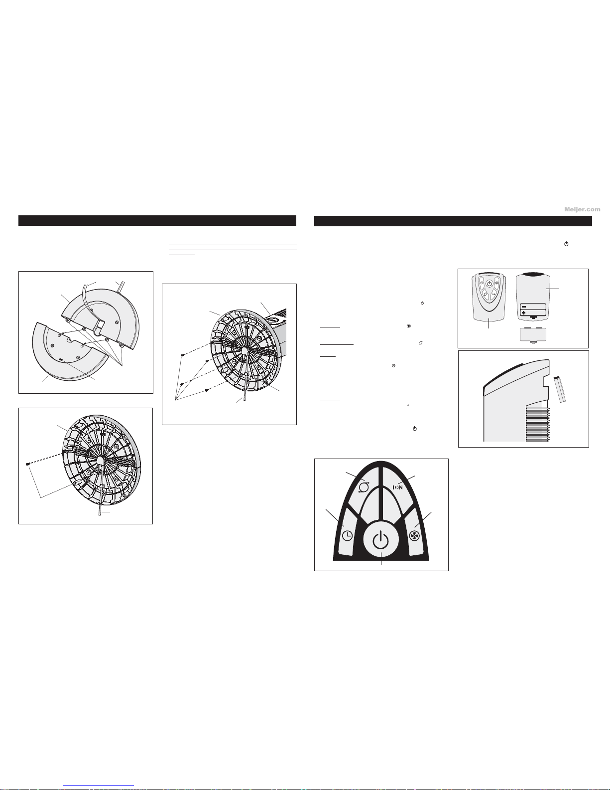
VENTILADOR DE TORRE XTRA AIR DE 48”
CON IONIZADOR Y CONTROL REMOTO
MODELO 4820
Meijer.com
Table of contents
Languages:
Other Lasko Fan manuals

Lasko
Lasko M16950 Owner's manual

Lasko
Lasko 1820 User manual

Lasko
Lasko PLATINUM DESKTOP WIND TOWER 4916 Owner's manual

Lasko
Lasko 7050 User manual

Lasko
Lasko 3012 Installation instructions manual

Lasko
Lasko Wind Tower 2519 User manual

Lasko
Lasko 2651 User manual

Lasko
Lasko S18605 User manual

Lasko
Lasko H20660 User manual

Lasko
Lasko 2527 User manual
Popular Fan manuals by other brands

Hunter
Hunter Anfield 53265 Owner's guide and installation manual

Fanimation
Fanimation Old Havana Series owner's manual

HAUTAU
HAUTAU VENTRA 302 E/N Maintenance and operating instructions

Salda
Salda AMBERAIR Installation, operation and maintenance manual

Fanelite
Fanelite PRICKLY 38YFT-7057M operating manual

Siemens
Siemens AD2-P installation instructions