Chicago Dryer AIR CHICAGO EXPRESS User manual

AIR CHICAGO®
EXPRESS
Towel Folder
INSTRUCTION MANUAL

©Chicago Dryer Company
Instruction Manual #3019-120
CHICAGO DRYER COMPANY
2200 N. Pulaski Road, Chicago, Illinois USA 60639-3737
Telephone: (773) 235-4430 Fax: (773) 235-4439 www.chidry.com

Air Chicago Express Table of Contents
i
TABLE OF CONTENTS
MANUAL
Chapter 1 - Introduction
Chapter 2 - Installation
Chapter 3 - Operating Guidelines
Chapter 4 - Preventive Maintenance
Chapter 5 - Operating Principles
Chapter 6 - Troubleshooting
Chapter 7 - Repair
CHI•TOUCH BULLETIN
PARTS LIST
SCHEMATICS
APPENDIX
Floor Plans
Technical Specifications
Torque Specifications
INDEX
TOC
INDEX

Table of Contents Air Chicago Express
ii
CHAPTER 1 INTRODUCTION
1.1 Warranty .................................................................................................. 1-2
1.2 Scope of Manual ..................................................................................... 1-2
1.3 Safety ...................................................................................................... 1-3
Safe Work Habits .................................................................................... 1-3
Safety Features ....................................................................................... 1-4
1.4 Optional Equipment ................................................................................. 1-6
TOC
INDEX

Air Chicago Express Table of Contents
iii
CHAPTER 2 INSTALLATION
2.1 Site and Utility Requirements .................................................................. 2-2
2.2 Installation Procedures ............................................................................ 2-3
Inspection ................................................................................................ 2-3
Uncrating and Positioning ....................................................................... 2-4
Compressed Air Supply Connection ....................................................... 2-5
Electrical Connection .............................................................................. 2-6
Final Protective Wrapper Removal .......................................................... 2-8
2.3 Pre-Operational Checkout ....................................................................... 2-8
Security of Hardware ............................................................................... 2-9
Compressed Air Supply Checkout .......................................................... 2-9
Ribbon Rotation Checkout .....................................................................2-11
Safety Device Checkout ........................................................................ 2-12
Primary Fold Operation Checkout ......................................................... 2-14
Crossfold Operation Checkout .............................................................. 2-15
Checkout Completion ............................................................................ 2-15
Cleaning the Unit ................................................................................... 2-15
TOC
INDEX

Table of Contents Air Chicago Express
iv
CHAPTER 3 OPERATING GUIDELINES
3.1 Safety Features ....................................................................................... 3-2
Main Disconnect Switch .......................................................................... 3-2
Safety STOP Buttons .............................................................................. 3-2
Air Permeable Barriers (Safety Guards) ................................................. 3-2
Safety Interlock Switches ........................................................................ 3-3
Safety Labels .......................................................................................... 3-3
3.2 Operating Controls .................................................................................. 3-4
3.3 Daily Operating Procedures .................................................................... 3-7
Start-Up ................................................................................................... 3-7
Handling Jams and Misfeeds Safely ....................................................... 3-9
Fold Operation ........................................................................................ 3-9
Interconnected Stop Circuit (Option) Operation Notes .......................... 3-12
Shut-Down ............................................................................................ 3-12
3.4 Operating Techniques ........................................................................... 3-13
Processing Standards ........................................................................... 3-13
Work Habits ........................................................................................... 3-14
TOC
INDEX

Air Chicago Express Table of Contents
v
CHAPTER 4 PREVENTIVE MAINTENANCE
PM Task Table .................................................................................................... 4-1
4.1 Daily PM (8 Hours) .................................................................................. 4-2
Watch and Listen for Anything Abnormal ................................................ 4-2
General Cleanliness ................................................................................ 4-2
Check and Clean Photosensors .............................................................. 4-3
Check Safety Equipment ......................................................................... 4-3
4.2 Weekly PM (50 Hours) ............................................................................ 4-4
Check and Clean Inverter ....................................................................... 4-4
Polish Metal Surfaces ............................................................................. 4-5
Check Stacker Drive Belt Condition and Tension .................................... 4-5
Check and Grease Stacker Door Bearings ............................................. 4-6
Inspect Air Filter/Auto Drain .................................................................... 4-7
Check Air Pressure Settings ................................................................... 4-7
Check Ribbon Condition and Tension ..................................................... 4-9
4.3 Monthly PM (200 Hours) ......................................................................... 4-9
Check Setscrews................................................................................... 4-10
Check and Clean Main Drive Motor ...................................................... 4-10
Clean and Lubricate Drive Chains .........................................................4-11
Lubricate Primary Fold Ski Bearings and Linkages .............................. 4-12
Check and Grease Bearings ................................................................. 4-13
4.4 Semi-Annual PM (1000 Hours) ............................................................. 4-14
Clean Air Filter/Auto Drain ..................................................................... 4-14
4.5 Annual PM (2000 Hours) ....................................................................... 4-15
Check All Electrical Connections ........................................................... 4-16
Check Insulation Resistance to Earth Ground ...................................... 4-16
TOC
INDEX

Table of Contents Air Chicago Express
vi
CHAPTER 5 OPERATING PRINCIPLES
Safety ................................................................................................................ 5-2
5.1 Electrical System ..................................................................................... 5-2
Power System ......................................................................................... 5-2
Control System ........................................................................................ 5-6
5.2 Compressed Air System ........................................................................ 5-10
Air Filter/Regulators............................................................................... 5-10
Air Pressure Switch ............................................................................... 5-10
Air Reservoirs ........................................................................................ 5-10
Air Valves/Air Valve Solenoids ...............................................................5-11
Air Cylinders ...........................................................................................5-11
Air Bars ...................................................................................................5-11
5.3 Mechanical System ............................................................................... 5-12
Main Drive System ................................................................................ 5-12
Second Crossfold Drive System ........................................................... 5-13
Stacker Drive System ............................................................................ 5-13
Exit Drive System .................................................................................. 5-13
Ribbon Sets ........................................................................................... 5-14
5.4 Sequence of Operation ......................................................................... 5-15
Stand-by Phase ..................................................................................... 5-15
Start-up Phase ...................................................................................... 5-16
Primary Fold Phase ............................................................................... 5-16
Crossfold Phrase ................................................................................... 5-17
Stacking Phase ..................................................................................... 5-17
Exit Phase ............................................................................................. 5-17
TOC
INDEX

Air Chicago Express Table of Contents
vii
CHAPTER 6 TROUBLESHOOTING
Troubleshooting Symptoms ............................................................................... 6-2
6.1 LED Diagnostics ...................................................................................... 6-4
6.2 Electrical .................................................................................................. 6-6
6.3 Mechanical ............................................................................................ 6-10
6.4 Primary Folding ..................................................................................... 6-12
6.5 First Crossfold ....................................................................................... 6-14
6.6 Second Crossfold .................................................................................. 6-15
6.7 Stacker .................................................................................................. 6-16
6.8 Exit Conveyor ........................................................................................ 6-17
6.9 Sensor Function .................................................................................... 6-18
6.10 Compressed Air System ........................................................................ 6-19
TOC
INDEX

Table of Contents Air Chicago Express
viii
CHAPTER 7 REPAIR
7.1 Safety Considerations ............................................................................. 7-2
7.2 Parts Availability ...................................................................................... 7-3
7.3 Ribbons and Rolls ................................................................................... 7-4
Primary Fold Ribbon Tension Adjustment ............................................... 7-5
First Crossfold Ribbon Tension Adjustment ............................................. 7-6
Transfer Ribbon Tension Adjustment ...................................................... 7-7
Second Crossfold Ribbon Tension Adjustment ....................................... 7-8
Stacker Ribbon Tension Adjustment ........................................................ 7-9
Exit Conveyor Ribbon Tension Adjustment ............................................. 7-9
Ribbon Replacement ............................................................................. 7-10
Tracking Tape Overview ........................................................................ 7-12
Exit Conveyor Ribbon Idler Roll Tracking Tape Replacement ............... 7-13
Riveted Tracking Tape Replacement ..................................................... 7-14
7.4 Chains and Belts ................................................................................... 7-16
Main Drive Chain Tension Adjustment ................................................... 7-17
Second Crossfold Ribbon Drive Chain Tension Adjustment .................. 7-18
Stacker Ribbon Drive Belt Tension Adjustment ..................................... 7-19
7.5 Sensors ................................................................................................. 7-20
Photosensor Replacement .................................................................... 7-20
Primary Fold Ski Position Detect Proximity Sensor Adjustment ............ 7-21
Primary Fold Ski Position Detect Proximity Sensor Replacement ........ 7-22
7.6 Compressed Air System ........................................................................ 7-23
Primary Fold Air Bar Alignment ............................................................. 7-24
Crossfold Air Bar Alignment .................................................................. 7-25
Primary Fold Ski Air Cylinder Air Flow Adjustment ................................ 7-26
Stacker Door Air Cylinder Air Flow Adjustment ..................................... 7-27
Air Valve Repair ..................................................................................... 7-28
TOC
INDEX

Air Chicago Express Repair
7-1
Chapter 7
REPAIR
Although designed for long service life, some individual consumable components of the Air Chicago®
Express eventually wear during normal use and must be adjusted or replaced. Adjustment and replacement
subjects covered are:
7.1 Safety Considerations 7.4 Chains and Belts
7.2 Parts Availability 7.5 Sensors
7.3 Ribbons and Rolls 7.6 Compressed Air System
As a general rule:
Replace ribbons when they are worn or break, when the tension can no longer be adjusted, or
when flatwork does not properly enter or exit the unit.
Replace tracking tape when it is worn smooth or when ribbons slip in place.
Follow the Preventive Maintenance Schedule at the beginning of the PREVENTIVE
MAINTENANCE chapter.
WARNING
Do not try to repair or correct any condition without reading and
understanding this Repair Chapter.
Only qualified personnel should troubleshoot and repair the machine.
WARNING
Always make sure the power is shut OFF at the main disconnect
switch before servicing the unit.
•
•
•
TOC
INDEX

Repair Air Chicago Express
7-2
7.1 Safety Considerations
Before attempting any repair work, review
these safety steps and precautions to protect
yourself and the machine.
Safety must always be the primary
concern of anyone making repairs or
adjustments.
Except where specifically directed, make
sure that power is turned OFF at the
main disconnect switch.
WARNING
Always use extreme caution
when performing any repair
procedure that requires the
unit to be operating.
Take every precaution
to keep hands and loose
clothing from coming into
contact with any moving
parts. Serious injury could
result.
Whenever the unit is running,
one person should be ready
at a red safety STOP button
at all times to stop the unit
if necessary.
All maintenance procedures should
be handled by at least two qualified
persons. Using the “buddy system”
facilitates a quicker procedure and
decreases the risk of an accident.
Always keep hands and clothing away
from the moving parts of the folder
when it must be running to make repairs
or adjustments.
•
•
•
•
Never bypass any of the unit’s safety
features. Only operate the unit with
endframe doors and all guards in
place and all safety features operating
correctly.
Never stand, sit or kneel on any part of
the unit.
Your site should lockout/tagout
procedures in place that comply with
government standards for performing
maintenance and repair. Ask your
supervisor for specific information.
WARNING
Know the proper lockout/
tagout procedures for
equipment during repair.
Follow the rules of your work
site. Failure to do so could
result in serious injury.
Do not repair or correct any
condition without reading
and understanding the repair
procedure.
Only qualified personnel
should troubleshoot and
repair this unit.
Always make sure that power
is disconnected before
servicing the unit.
•
•
•
TOC
INDEX

Air Chicago Express Repair
7-3
7.2 Parts Availability
Replacement and repair parts can be ordered
through your local authorized CHICAGO®
distributor. Questions about the operation,
maintenance, troubleshooting, or repair of the
folder can also be directed to your distributor.
Orders may also be placed directly with the
Chicago Dryer Company Parts Department.
Questions may be directed to your local authorized
CHICAGO® dealer or the service department at
(773) 235-4430.
NOTE: Use only factory warranty
tested and approved replacement
parts when repairing a CHICAGO®
unit. They are designed for each
specific model and serial number
folder. Overnight shipment of parts
is available.
TOC
INDEX

Repair Air Chicago Express
7-4
Primary Fold Ribbons
Stacker Ribbons Second Crossfold Ribbons
Transfer Ribbons
First Crossfold Ribbons
Exit Conveyor Ribbons
Figure 7-1: Air Chicago Express ribbons sets.
7.3 Ribbons and Rolls
Flatwork is directed through the folder by
several sets of ribbons (Figure 7-1). In order for
the machine to do its work properly, these ribbon
sets must be kept adjusted and aligned. Failure
to do so can increase the likelihood of jams or
other malfunctions.
With extended use, ribbons may begin to sag
or track to one side of the unit. Both conditions
cause excessive wear and shorten ribbon life, so
tension should occasionally be adjusted for better
finish and longer ribbon life.
In addition, the unit should never be operated
with broken or missing ribbons.
The following procedures are included:
Primary Fold Ribbon Tension
Adjustment
First Crossfold Ribbon Tension
Adjustment
Transfer Ribbon Tension Adjustment
Second Crossfold Ribbon Tension
Adjustment
Stacker Ribbon Tension Adjustment
Exit Conveyor Ribbon Tension
Adjustment
Ribbon Replacement
•
•
•
•
•
•
•
Turning rolls power the ribbons. Materials
attached to various rolls grip the ribbons to
ensure their proper movement. Over time, these
materials can become worn or damaged and must
be replaced. This includes:
Tracking Tape Replacement
Overview
Gray (Exit Conveyor Rolls) Tracking
Tape
Black (All Folder Rolls w/Tape) Track-
ing Tape
•
a)
b)
c)
TOC
INDEX
Air Chicago Express Repair
7-5
Primary Fold Ribbon Tension
Adjustment
Required Tools
Wrenches:
3/8”
9/16”
Perform only when the unit is OFF
with power disconnected.
Turn power OFF at the main disconnect
switch.
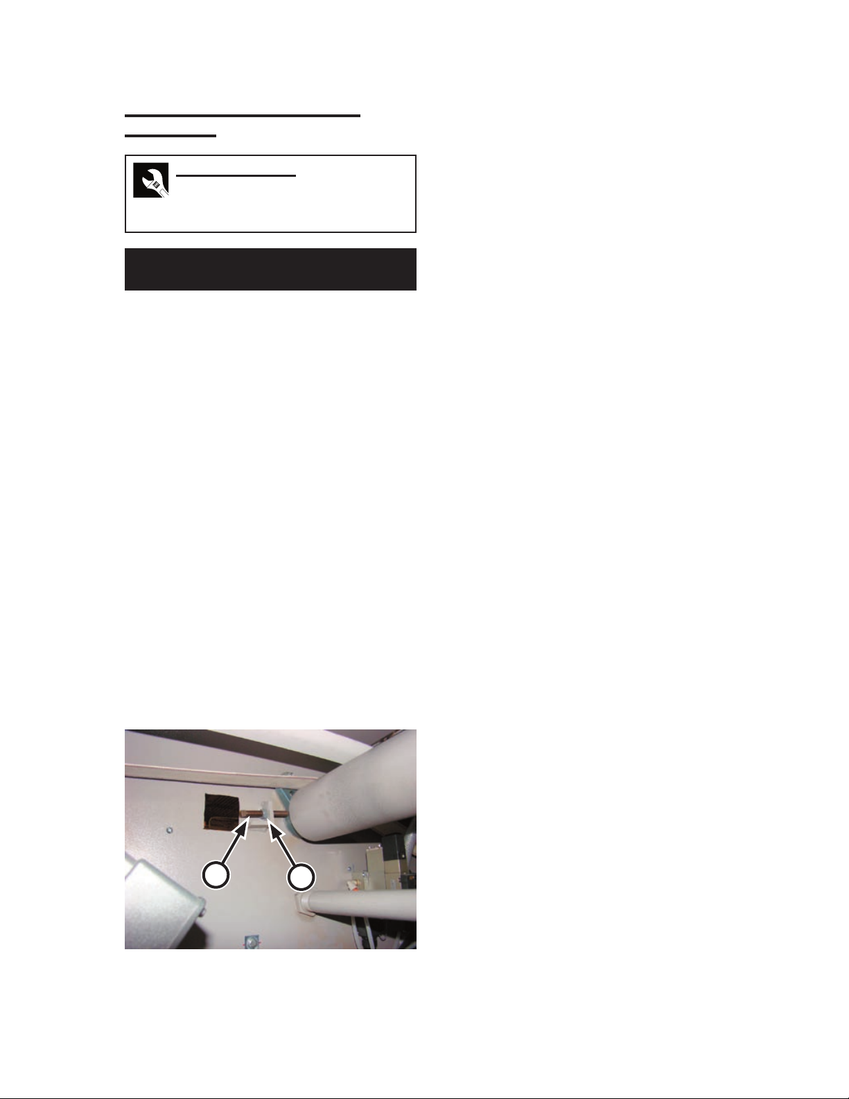
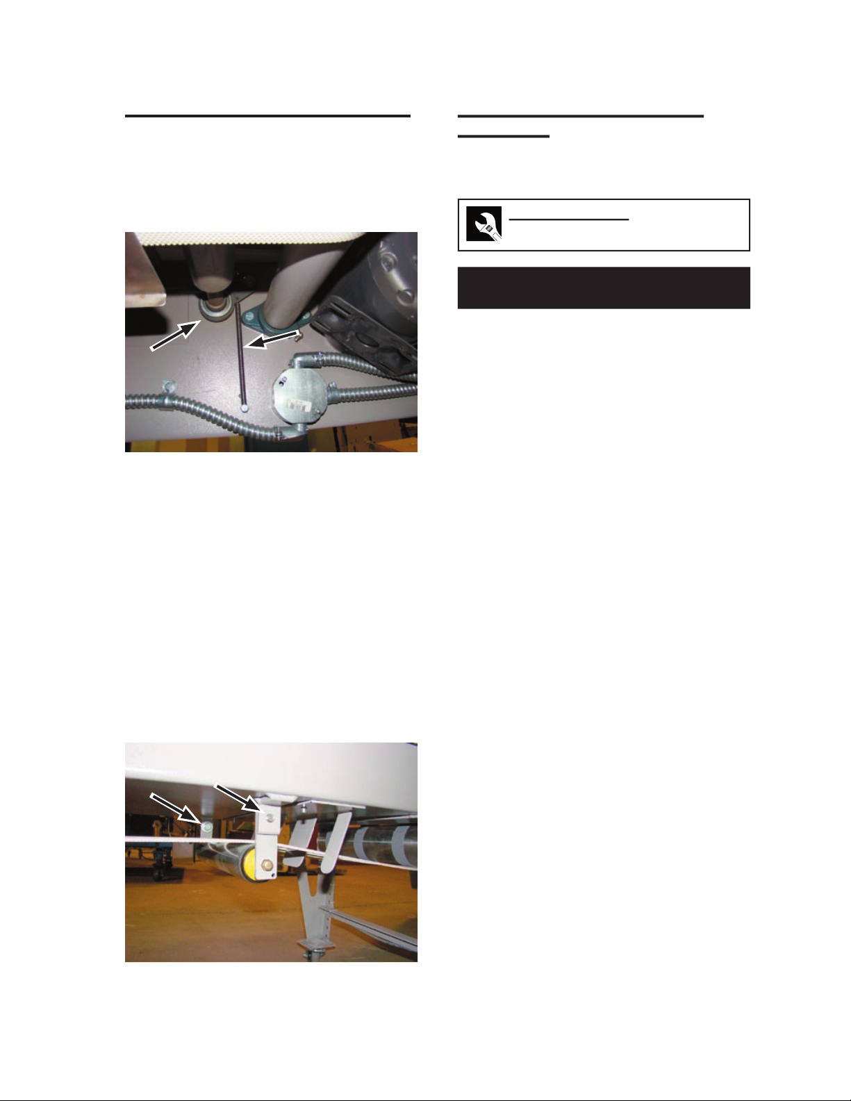
Under the unit at the front, locate the
primary fold ribbons idler roll tension
adjustment bolts (Figure 7-2, A). There is
one on each side of the machine.
While holding each adjustment bolt in
place, loosen its locknut (Figure 7-2, B).
Adjust each bolt the same number of turns
clockwise until the ribbons have the proper
tension.
1.
2.
3.
4.
Turn power ON at the main disconnect
switch.
Run the unit briefly and make sure the
ribbons track straight.
If tension on the ribbons is uneven, the
ribbons will track toward the end of the
drive roll where tension is highest.
Stop the unit and turn power OFF at the
main disconnect switch.
Either turn the adjusting bolt counter-
clockwise at the high tension end, or turn
the adjusting bolt clockwise at the low
tension end.
Repeat Steps 5 to 9 until the ribbons have
the correct tension and track evenly.
Stop the unit and turn power OFF at the
main disconnect switch.
While holding each adjustment bolt in
place, secure its locknut.
5.
6.
7.
8.
9.
10.
11.
12.
Figure 7-2: Primary fold ribbon tension
adjustment.
AA
TOC
INDEX
Repair Air Chicago Express
7-6
First Crossfold Ribbon Tension
Adjustment
Required Tools
Wrenches:
3/8”
9/16”
Perform only when the unit is OFF
with power disconnected.
Turn power OFF at the main disconnect
switch.
Remove both rear endframe panels.
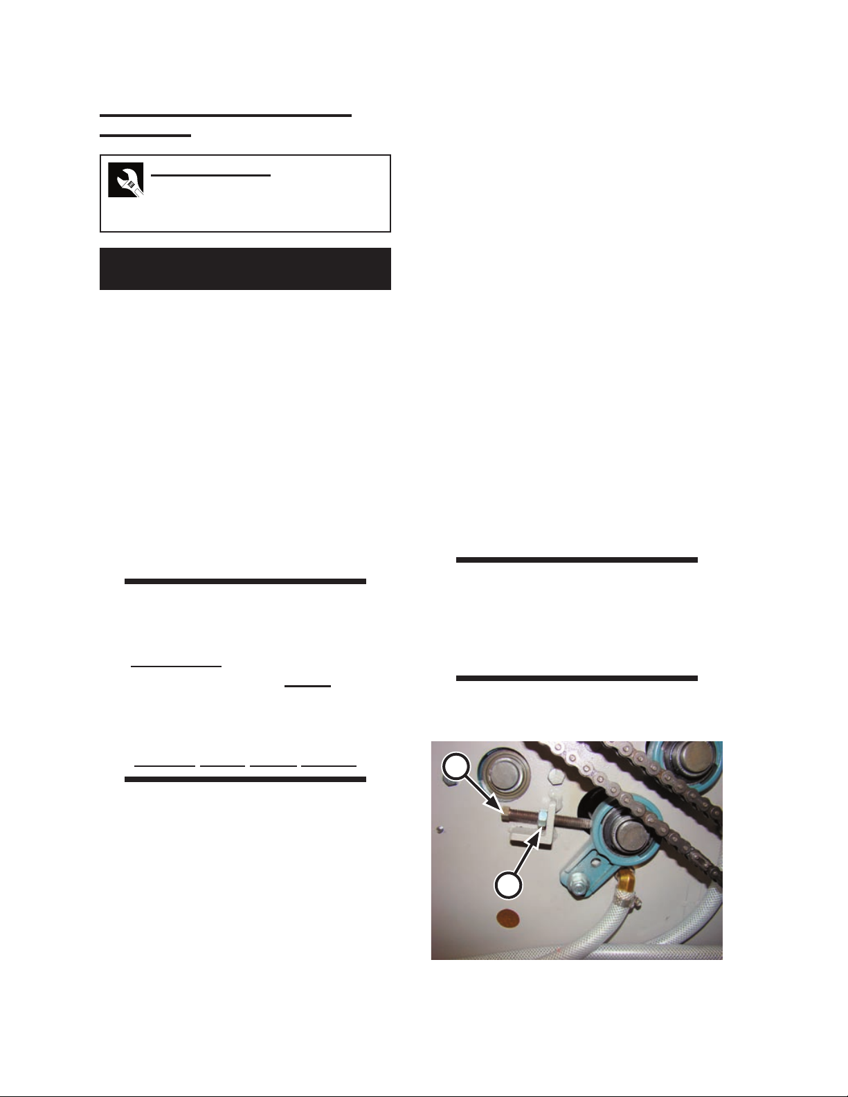
Locate the first crossfold ribbons drive
roll tension adjustment bolts (Figure 7-
3, A). There is one on each side of the
machine.
While holding each adjustment bolt in
place, loosen its locknut (Figure 7-3, B).
Adjust each bolt the same number of turns
until the ribbons have the proper tension.
WARNING
This safety interlock switch
is only to be defeated
temporarily while performing
this procedure. Never
operate the unit unless
all safety systems
are working correctly.
Serious Injury Could Result.
The machine will not operate while a
safety microswitch is open. As a tempo-
rary measure during this work, defeat each
endframe interlock switch by inserting
one of the switch keys that shipped with
the unit.
Turn power ON at the main disconnect
switch.
1.
2.
3.
4.
5.
6.
7.
Run the unit briefly and make sure the
ribbons track straight.
If tension on the ribbons is uneven, the
ribbons will track toward the end of the
drive roll where tension is highest.
Stop the unit and turn power OFF at the
main disconnect switch.
Either turn the adjusting bolt counter-
clockwise at the high tension end, or turn
the adjusting bolt clockwise at the low
tension end.
Repeat Steps 7 to 11 until the ribbons have
the correct tension and track evenly.
Stop the unit and turn power OFF at the
main disconnect switch.
While holding each adjustment bolt in
place, secure its locknut.
Remove the interlock switch keys; then,
replace and secure the endframe panels.
WARNING
Never operate the unit unless
all safety covers are in place
and all safety equipment is
working correctly.
8.
9.
10.
11.
12.
13.
14.
15.
Figure 7-3: First crossfold ribbon tension
adjustment.
B
A
TOC
INDEX
Air Chicago Express Repair
7-7
Transfer Ribbon Tension Adjustment
Required Tools
Wrenches:
3/8”
9/16”
Perform only when the unit is OFF
with power disconnected.
Turn power OFF at the main disconnect
switch.
Remove both rear endframe panels.
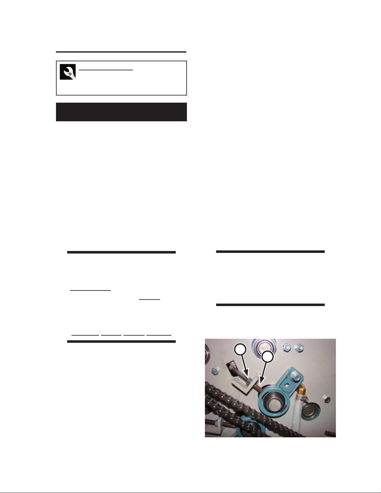
Locate the transfer ribbons idler roll
tension adjustment bolts (Figure 7-4,
A). There is one on each side of the ma-
chine.
While holding each adjustment bolt in
place, loosen its locknut (Figure 7-4, B).
Adjust each bolt the same number of turns
until the ribbons have the proper tension.
WARNING
This safety interlock switch
is only to be defeated
temporarily while performing
this procedure. Never
operate the unit unless
all safety systems
are working correctly.
Serious Injury Could Result.
The machine will not operate while a
safety microswitch is open. As a tempo-
rary measure during this work, defeat each
endframe interlock switch by inserting
one of the switch keys that shipped with
the unit.
Turn power ON at the main disconnect
switch.
1.
2.
3.
4.
5.
6.
7.
Run the unit briefly and make sure the
ribbons track straight.
If tension on the ribbons is uneven, the
ribbons will track toward the end of the
drive roll where tension is highest.
Stop the unit and turn power OFF at the
main disconnect switch.
Either turn the adjusting bolt counter-
clockwise at the high tension end, or turn
the adjusting bolt clockwise at the low
tension end.
Repeat Steps 7 to 11 until the ribbons have
the correct tension and track evenly.
Stop the unit and turn power OFF at the
main disconnect switch.
While holding each adjustment bolt in
place, secure its locknut.
Remove the interlock switch keys; then,
replace and secure the endframe panels.
WARNING
Never operate the unit unless
all safety covers are in place
and all safety equipment is
working correctly.
8.
9.
10.
11.
12.
13.
14.
15.
Figure 7-4: Transfer ribbon tension adjustment.
A
B
TOC
INDEX
Repair Air Chicago Express
7-8
Second Crossfold Ribbon Tension
Adjustment
Required Tools
Wrenches:
3/8”
9/16”
Perform only when the unit is OFF
with power disconnected.
Turn power OFF at the main disconnect
switch.
Remove both rear endframe panels.
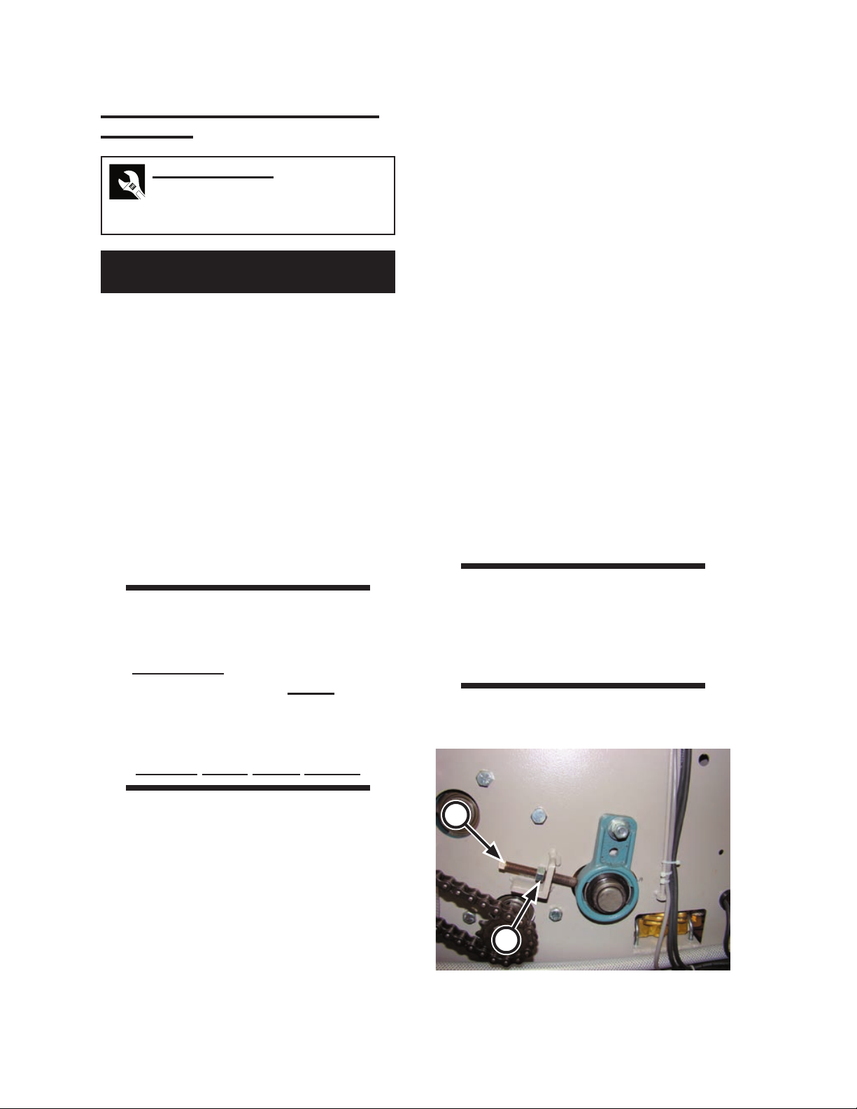
Locate the first crossfold ribbons drive
roll tension adjustment bolts (Figure 7-
5, A). There is one on each side of the
machine.
While holding each adjustment bolt in
place, loosen its locknut (Figure 7-5, B).
Adjust each bolt the same number of turns
until the ribbons have the proper tension.
WARNING
This safety interlock switch
is only to be defeated
temporarily while performing
this procedure. Never
operate the unit unless
all safety systems
are working correctly.
Serious Injury Could Result.
The machine will not operate while a
safety microswitch is open. As a tempo-
rary measure during this work, defeat each
endframe interlock switch by inserting
one of the switch keys that shipped with
the unit.
Turn power ON at the main disconnect
switch.
1.
2.
3.
4.
5.
6.
7.
Figure 7-5: Second crossfold ribbon tension
adjustment.
B
A
Run the unit briefly and make sure the
ribbons track straight.
If tension on the ribbons is uneven, the
ribbons will track toward the end of the
drive roll where tension is highest.
Stop the unit and turn power OFF at the
main disconnect switch.
Either turn the adjusting bolt counter-
clockwise at the high tension end, or turn
the adjusting bolt clockwise at the low
tension end.
Repeat Steps 7 to 11 until the ribbons have
the correct tension and track evenly.
Stop the unit and turn power OFF at the
main disconnect switch.
While holding each adjustment bolt in
place, secure its locknut.
Remove the interlock switch keys; then,
replace and secure the endframe panels.
WARNING
Never operate the unit unless
all safety covers are in place
and all safety equipment is
working correctly.
8.
9.
10.
11.
12.
13.
14.
15.
TOC
INDEX
Air Chicago Express Repair
7-9
Stacker Ribbon Tension Adjustment
Tension on the stacker ribbons is maintained
by a spring-tensioned idler roll (Figure 7-6).
If proper tension on the ribbons is not being
maintained, the spring has stretched and must
be replaced.
Figure 7-6: Stacker ribbon tension is maintained
by a spring-tensioned idler roll.
Exit Conveyor Ribbon Tension
Adjustment
Front Conveyor Section
Required Tools
Wrenches: 9/16”
Perform only when the unit is OFF
with power disconnected.
Turn power OFF at the main disconnect
switch.
Locate the exit conveyor tensioning idler
(Figure 7-7).
Loosen the bolts which secure the idler
in position.
Pivot the idler until the ribbons have the
proper tension.
Secure the bolts.
Turn power ON at the main disconnect
switch.
Run the unit briefly and make sure the
ribbons track straight.
If tension on the ribbons is uneven, the
ribbons will track toward the end of the
drive roll where tension is highest.
Stop the unit and turn power OFF at the
main disconnect switch.
Make sure the roll is parallel with the
conveyor.
Repeat Steps 5 to 9 until the ribbons have
the correct tension and track evenly.
Stop the unit and turn power OFF at the
main disconnect switch.
1.
2.
3.
4.
5.
6.
7.
8.
9.
10.
11.
12.
Figure 7-7: Exit conveyor ribbon tension
adjustment.
TOC
INDEX
Repair Air Chicago Express
7-10
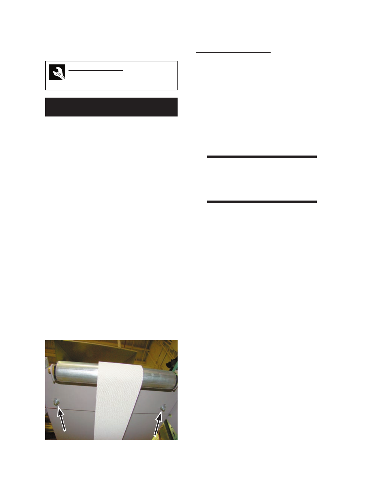
Rear Conveyor Section
Required Tools
Phillips screwdriver: #3
Wrench: 7/16”
Perform only when the unit is OFF
with power disconnected.
Turn power OFF at the main disconnect
switch.
Loosen the nuts (Figure 7-8) holding the
adjustable plate in place.
Move the plate until the ribbon is snug.
Secure the nuts while holding the screws
in place.
Turn power ON at the main disconnect
switch.
Run the unit briefly and make sure the
ribbon tracks straight.
If the tension on the ribbon is uneven,
it will track toward the end where the
tension is highest. Stop the unit and turn
power OFF at the main disconnect switch.
Either reduce tension at the highest end or
increase at the low end.
Repeat Steps 1 to 7 until the ribbon has the
correct tension and track evenly.
1.
2.
3.
4.
5.
6.
7.
8.
Ribbon Replacement
Over a period of time, ribbons stretch. When
the tension on a set of ribbons can no longer
be adjusted, the entire set of ribbons must be
replaced.
Ribbons that break should be replaced
immediately. It is recommended that the entire set
of ribbons be replaced in order to avoid excessive
stress on only one new (slightly shorter) ribbon.
At a minimum, it is recommended that ribbons
be replaced in pairs.
WARNING
Make sure power is shut
OFF at the main disconnect
switch.
To replace a broken ribbon, remove one ribbon
from BOTH ends of the machine and use one to
replace the broken ribbon following the procedure
below. Then follow this procedure to replace the
ribbons at BOTH ends of the machine with new
ribbons.
Figure 7-8: Ribbon tension adjustment screws.
TOC
INDEX
Other manuals for AIR CHICAGO EXPRESS
2
Table of contents
Other Chicago Dryer Folding Machine manuals


