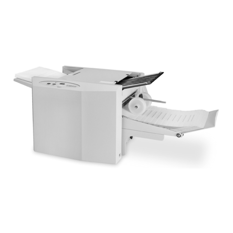
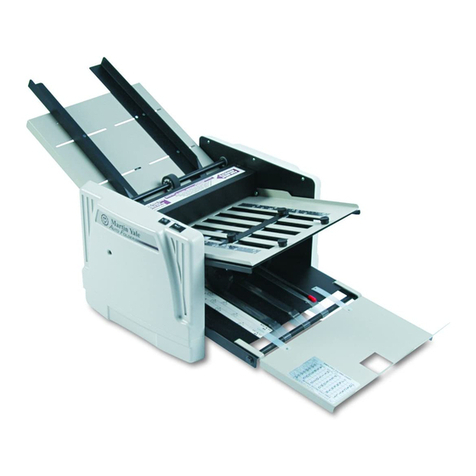
Horizon Fitness AFC-566F User manual

I
• This manual is designed to help you to install, operate and maintain the AFC-
566F Cross Folder. Please read and understand this manual, and keep it in a
safe and convenient place.
• Do not operate the AFC-566F until you read and understand the instructions in
this manual.
• Horizon International Inc. shall not be liable for incidental consequential
damages resulting from: improper or inadequate maintenance by the customer,
unauthorized modification or misuse, or operation outside of the environmental
specifications for the product.
• Horizon International Inc. pursues a policy of continuing improvement in design
and performance of the product. Therefore, the product design and
specifications are subject to change without prior notice and without our legal
obligation.
• All rights are reserved. No part of this manual may be photocopied, reproduced
or translated to another language without the prior written consent of Horizon
International Inc.
Important Information
CROSS FOLDERCROSS FOLDER
AFC-566F
170228/566F/32E/TI,TM,AT/F7/ICS5.5/PXI UM203051-32(000)
*UM203051*

II
Safety Precautions
Safety precautions are indicated in this manual as follows:
The term WARNING indicates a potentially hazardous situation which, if not
avoided, could result in death or serious injury.
The term CAUTION indicates a potentially hazardous situation which, if not
avoided, may result in serious injury, or damage to the machine.
This symbol indicates a note which includes important information. Follow
the note to operate the machine safely.
This symbol indicates a prohibited action. Do not perform any prohibited
action.
This symbol indicates an essential procedure. Follow the procedure to
operate the machine safely.
Important • This lists the range of acceptable values and operating
conditions.
Attention • This information will help you to avoid problems with the
machine or help you learn how to operate the machine.
Note • Refer to this note when you operate the machine.
Additional
Information
• This explains a mechanism in the machine.

III
Operating Safety Precautions
WARNINGS for Operation
The machine must be operated by just one person at a time.
Keep your hands and fingers away from the rotor and any moving parts during opera-
tion. Otherwise moving parts can cause severe personal injury.
Rotating parts may catch your hair or clothing. Arrange your hair in a bun or wear suit-
able clothing. Otherwise rotating parts can cause severe personal injury.
Do not remove or bypass any safety features. Moving parts can cause severe personal
injury.
Press the Emergency Stop button before turning the handwheel. A sudden accidental
start of the machine can cause severe personal injury.
Turn off the power switch before adjusting the machine unless instructed otherwise. If
the Start button is pressed, the machine may move suddenly and cause severe per-
sonal injury.
Turn off the power switch before resetting the circuit breakers. Otherwise, the machine
may start suddenly, causing severe personal injury.
CAUTIONS for Operation
Be sure to install the buckle chutes and conveyors correctly. Otherwise, the machine
may be damaged.
If the power is turned off, wait at least ten seconds before turning the power on again.
When you are moving the perforation blades sideways, be sure to raise the upper per-
foration shaft before moving the blades. After moving the blades, return the upper per-
foration shaft to its original position. If you do not do this, the blades may be damaged.
Do not place any objects under the feed table. Otherwise, the feed table may be dam-
aged.

IV
WARNINGS for Installation
Be sure to attach the cables, hoses, tubes in the areas where a foot cannot be caught.

V
Warning Label Locations and Meanings
There are electrical parts inside. Be careful when you open the cover. Oth-
erwise, electrical shock may be caused.
Do not approach your hands and fingers while the belt is rotating. Other-
wise your hands and fingers may be caught by the rotating belt.
Do not touch the perforation blade with bear hand. Make sure to wear cut-
ting proof gloves when handling the perforation blade. Otherwise sharp
blade can cause severe personal injury.
Do not approach your hands and fingers while the roller is rotating. Other-
wise your hands and fingers may be caught by the rotating roller.
Do not insert your hands and fingers inside the cover. There are gears inside
and your hands and fingers may be caught by the gears.
When you lower the suction head bar, be careful not to catch your finger.
Do not insert your fingers into the slit of the feed head while the feed table
is moving. Otherwise, the moving table can cause severe personal injury.
Do not approach your hands and fingers to the suction head while the suc-
tion head is moving to the minimum or maximum position. Otherwise your
hands and fingers may be caught by the suction head.
23051
10101B1

VI
CONTENTS
Important Information................................................................................................I
Safety Precautions...................................................................................................II
Operating Safety Precautions.................................................................................III
Warning Label Locations and Meanings.................................................................V
1. Machine Description
1-1 Machine Description .......................................................................................1
1-1-1 Overall View 1 ........................................................................................................................1
1-1-2 Overall View 2 ........................................................................................................................2
1-1-3 Overall View 3 ........................................................................................................................3
1-1-4 Suction Head Section 1 .........................................................................................................4
1-1-5 Suction Head Section 2 .........................................................................................................5
1-1-6 Feed Rotor Section ................................................................................................................6
1-1-7 Side Air and Feed Table ........................................................................................................7
1-1-8 Register Guide Section ..........................................................................................................8
1-1-9 Buckle Chute Section .............................................................................................................9
1-1-10 Perforation and Scoring Section ........................................................................................10
1-1-11 Knife Fold Section ..............................................................................................................11
1-1-12 Buckle Chute Below Knife .................................................................................................12
1-1-13 Conveyor Section ...............................................................................................................13
1-1-14 Power Box and Control Box ..............................................................................................14
1-1-15 Pump Section .....................................................................................................................15
1-1-16 Control Panel ......................................................................................................................16
1-1-17 Sub Control Panel ..............................................................................................................17
1-1-18 Remote Controller ..............................................................................................................18
1-2 Touch Panel Description...............................................................................19
1-2-1 Initial Screen .........................................................................................................................19
1-2-2 Main - Function Screen .......................................................................................................19
1-2-3 Main - Condition Screen .....................................................................................................20
1-2-4 Main - Options Screen ........................................................................................................21
1-2-5 Set Up - Fold Pattern Screen ...............................................................................................22
1-2-6 Set Up - Guide-Buckle Screen ............................................................................................23
1-2-7 Set Up - Register Mark Position Entering Screen ...............................................................24
1-2-8 Set Up - Roller Gap Screen .................................................................................................25
1-2-9 Set Up - Roller Gap Micro-Adjusting Screen .......................................................................26
1-2-10 Set Up - Check/Instruction Screen ....................................................................................27
1-2-11 Set Up - Reset Screen .......................................................................................................28
1-2-12 Memory Screen ..................................................................................................................29
1-2-13 Properties Screen ..............................................................................................................30
1-2-14 Properties - Administrator Setting Screen .........................................................................31
2. Overview of Setup Procedure
2-1 Overview of Basic Setup...............................................................................33
2-2 Overview of Fine-Tuning...............................................................................34
3. Basic Setup
3-1 Turn On the Power Switch............................................................................37

VII
3-2 Setting the Fold Pattern and Sheet Size.......................................................38
3-3 Setting the Positions of the Guides and Buckle Chutes................................41
3-4 Loading the Sheets on the Table..................................................................43
3-5 Setting the Suction Head..............................................................................46
3-6 Setting the Register Guide............................................................................50
3-7 Setting the Perforation Blades......................................................................51
3-8 Setting the Knife Fold Section.......................................................................53
3-9 Setting the Conveyor Section .......................................................................54
4. Fine-Tuning Adjustments
4-1 Setting the Belt Speed..................................................................................57
4-2 Feed One Sheet in Setup Mode ...................................................................58
4-3 Checking the Sheet Feeding Angle ..............................................................59
4-4 Adjusting Fold Skew in Parallel Folding........................................................60
4-5 Adjusting Parallel Shifts in Parallel Folding...................................................65
4-5-1 Adjusting the positions of the buckle stoppers separately ..................................................65
4-5-2 Adjusting the positions of the buckle stoppers at once ......................................................66
4-6 Matching the Perforation Line to the Fold.....................................................67
4-7 Setting the Perforation Blades and Scoring Blades......................................71
4-8 Setting the Knife Fold Section.......................................................................75
4-9 Adjusting Fold Skew on Buckle Chute below Knife ......................................77
4-10 Adjusting Fold Shifts on Buckle Chute below Knife......................................81
4-11 Checking the Fold Quality.............................................................................82
4-12 Other Adjustments........................................................................................83
4-12-1 Feed rotor section adjustment ...........................................................................................83
4-12-2 Buckle gate adjustment ......................................................................................................85
4-12-3 Gap adjustments inside the buckle chutes ........................................................................86
4-12-4 Gap adjustments between the buckle chutes and fold rollers ..........................................87
4-12-5 Stopper angle adjustment ..................................................................................................88
4-12-6 Fold knife angle adjustment ...............................................................................................89
4-12-7 Adjustment of the hold-down roller pressure in the fold section .......................................90
5. Starting and Running the Job
5-1 Setup the Main Screen .................................................................................91
5-1-1 Setup the Function Screen .................................................................................................91
5-1-2 Set up the Condition Screen ...............................................................................................92
5-2 Starting Folding.............................................................................................95
6. Troubleshooting
6-1 If an Error Icon Appears on the Screen ........................................................97
6-2 If a System Error Code Appears on the Screen..........................................101
6-3 Problems in the Feed Section.....................................................................104
6-3-1 The suction piston does not pick up the sheet ..................................................................104
6-3-2 The feed rotor does not rotate ...........................................................................................105
6-3-3 The vacuum piston moves slowly ......................................................................................105
6-3-4 The feed table does not move up and down .....................................................................105
6-3-5 The right end of the sheet moves ......................................................................................105
6-4 Problems in the Register Guide Section.....................................................106
6-4-1 Sheet does not move up against the register guide, or hits the register guide too hard .106

VIII
6-4-2 Large size sheets are not fed straight ...............................................................................106
6-5 Problems in the Buckle Chute Section........................................................107
6-5-1 The sheet does not enter the buckle chute .......................................................................107
6-5-2 The folds are not square to the edges of the sheet ..........................................................108
6-5-3 The sheets are wrinkled parallel to the fold line ................................................................109
6-5-4 The sheets are wrinkled across the fold line .....................................................................109
6-5-5 One of the folding lines is unstable ....................................................................................109
6-5-6 The sheet remains inside the buckle chute .......................................................................110
6-6 Problems in the Scoring Section.................................................................111
6-6-1 The scoring line does not run straight ...............................................................................111
6-6-2 The perforation line does not run in the center .................................................................111
6-7 Problems in the Knife Section.....................................................................112
6-7-1 The sheets are scratched or smeared ...............................................................................112
6-7-2 The fold knife creases the sheets ......................................................................................112
6-7-3 The sheets are not folded exactly on the perforation line .................................................112
6-7-4 The folded edge of the signature swells up .......................................................................113
6-7-5 The knife does not work .....................................................................................................113
6-7-6 The roller below the knife does not rotate .........................................................................113
6-8 Other Problems...........................................................................................114
6-8-1 The sheets are not arranged correctly on the delivery conveyor .....................................114
6-8-2 The delivery conveyor does not run ..................................................................................114
6-8-3 The pump pressure does not increase when you turn the regulator knob ......................115
6-8-4 The pump does not run ......................................................................................................115
6-8-5 The motor does not run when the Start button is pressed ................................................115
6-8-6 The display does not appear when the main power is turned on .....................................115
6-8-7 The gate fold buckle chute does not operate ....................................................................116
6-8-8 Sheets cannot be fed continuously ....................................................................................116
6-9 General Folding Problems and Remedies..................................................117
6-10 If a Message Screen is Displayed...............................................................122
7. Maintenance
7-1 Cleaning the Vacuum Piston.......................................................................123
7-2 Disassembling and Cleaning the Pump Filter.............................................125
7-3 Cleaning the Fold Roller .............................................................................126
7-4 Lubrication ..................................................................................................127
7-4-1 Lubricating the Grease Nipple ...........................................................................................127
7-4-2 Lubricating the Conveyor Drive Chain ...............................................................................128
7-5 Removing and Installing the Perforation Shaft............................................129
7-6 Removing the Buckle Chute .......................................................................130
7-7 Installing the Perforation Blade...................................................................132
7-8 Cleaning the Double Feed Detect Photoelectronic Sensor.........................135
7-9 Cleaning and Replacing the Air Filter in the Control Box............................136
7-10 Replacing the Carbon Blades of Pump.......................................................137
7-11 Replacing the Battery for the Remote Controller........................................138
8. Installation
8-1 Machine Installation....................................................................................139
8-1-1 Placing the Machine ...........................................................................................................139
8-1-2 Level Adjustment ................................................................................................................140
8-1-3 Installing the Delivery Section Front Cover .......................................................................140


IX
8-2 Pump Power Cable Connection..................................................................141
8-3 Pump Power Cable Connection..................................................................142
8-4 Installing the Conveyor and Accessories....................................................143
8-5 Installing the Conveyor and Accessories....................................................144
8-6 Connecting the Power Cables ....................................................................145
8-7 Pump Rotation Direction.............................................................................145
8-8 Date and Time Setup..................................................................................146
8-9 Checks After Installation.............................................................................146
9. Appendix
9-1 Specifications..............................................................................................147
9-2 Accessories.................................................................................................148
9-3 Consumables..............................................................................................152
9-4 Options .......................................................................................................153
9-5 De-commissioning and Dismantling............................................................154
9-6 Static and Dynamic Load Testing...............................................................155

This page is intentionally left blank.

1
Machine Description / Machine Description
1. Machine Description
1-1-1 Overall View 1
1-1 Machine Description 1-1-1
Overall View 1
The directions in this manual are
indicated as follows:
Left
Right
Rear, Back
Front, Operator Side
23051
10101A1
Page 9
Buckle Chutes 1, 3, and 5
Pump Section
Suction Head Section
The vacuum piston pulls up
the top sheet, and separates
it from other sheets. The
suction head section
changes position automati-
cally to match the sheet
length. Page 4
Power Switch
Page 8
Control Panel (LCD)
Register Guide
This panel is used to control the folding operation.
Page 16
Page 15
Conveyor Section
Page 13
Sub Control Panel Section
Page 17
Feed Rotor Section
This rotor feeds one sheet at a
time to the register guide.
Page 6
Buckle Chutes 2, 4, and 6

2
1-1 Machine Description 1-1-2
Overall View 2
23051
10102A1
Knife Folding
Section
Page 11
Parallel Folding
Exit Section
Handwheel for Knife
Fold Roller
This wheel is used to turn the
fold roller below the knife.
When the wheel is pulled out
and rotated, the fold roller can
be turned manually. When the
wheel is pressed in, the roller is
not engaged with the wheel.
Cross Folding Exit Section
Buckle Chutes K1 and K2
Handwheel
When the wheel is pulled out and rotated, thefold
rollers can be turned manually. When the wheel
is pressed in, the rollers are not engaged with the
wheel.
Feed Table
The maximum stack
height is 740 mm (29.1").
Feed Table Knob
This wheel moves the feed table to
the front and rear.
The handwheel may turn suddenly and cause
injury. Press the Emergency Stop button before
turning the handwheel.
WARNING
1-1-2 Overall View 2

3
Machine Description / Machine Description
1-1-3
Overall View 3
1-1 Machine Description
23051
10103A1
Control Box Fan - Air Filter
This fan cools the control box.
The air filter must be cleaned
regularly.
Power Box
This contains circuit
breakers.
Page 14
Door for Buckle Chute
Below the Knife
Open this door to remove
buckle chute K2. If this cover is
opened while operation, the
machine stops.
Control Box
This contains the circuit breakers.
Page 14
Power Connector to Round
Feeder (option)
Power Connector to Gate Fold
Buckle Chute (option)
Conveyor Power Connector
Communication Connector to
Press Stacker (option)
1-1-3 Overall View 3
Top Cover
If this cover is opened while
operation, the machine stops.

4
1-1-4
Suction Head Section 1
1-1 Machine Description
23051
10104A1
Sheet Hold-down Weights
These weights help to control the sheet.
Attach or remove weights to match the
type of sheet.
Set Register Pin Locking Knob
Suction Piston Height Adjusting
Knob
This knob is used to adjust the
space between the suction cup
and the top of the stack.The
standard space is about 1mm
(0.04”).
Set Register Pin
Fit the pin against the back of the stack. Air Guide
This guide holds the sheet lightly
and prevents the separation air from
leaking out to the sides.
Blower Air Nozzle
The blower air exits. Grip Area Adjusting Knob
Turn the knob clockwise to move the
grip area forward.
Sheet Hold Angle Adjusting
Knob
Turn the knob clockwise to increase the
angle.
Blower Air Position Adjusting
Knob
This knob is used to adjust the height of
the blower air nozzles.
Sheet Hold-down Pres-
sure Adjusting Knob
Thisknob adjusts thepressure
produced by the sheet hold-
down bar against the sheet.
The higher the setting on this
knob, the greater the hold-
down pressure.
Sheet Hold-down Bar
This holds down the rear
edge of the stack.
The suction head section adjusts position automatically during changeover to match the sheet length.
1-1-4 Suction Head Section 1
BlowerAirPressureAdjusting
Knob
Separation Air Pressure
Air Guide
Suction Head Stop Switch
When the vacuum piston picks up the
sheets which width is narrow, the suction
head can rise a little, and the gap between
the vacuum piston and sheets can widen.
In this case, turn off this switch so as not to
move the vacuum piston.
When lowering the feed table, the suc-
tion head raises even if this switch is
turned off. And when raising the feed
table with this switch turned off, the suc-
tion head does not lower and cannot
catch the sheet. Be sure to turn this
switch on before raising the feed table.

5
Machine Description / Machine Description
1-1-5
Suction Head Section 2
1-1 Machine Description
23051
10105A1
23051
10105B1
Separator
This separator holds the sheet
edge lightly and prevents the
sheet from double feeding.
Adjust the grip area according to
the sheet weight.
Outlet for Separation Air
Separation air is blown between the upper-
most sheet lifted by the vacuum piston and
the lower sheet which is held by the separator.
Support Release Lever
Suction Head Support Lifting Handle
Suction Head Arm
This supports the arm when it is
raised.
Communication Connector for
Round Feeder (option)
Connector for Suction Head
Lock Nut
Piston Set Screw
Vacuum Piston
This piston catches the top
sheet and lifts it up.
Suction Cup
If this is torn, replace it.
1-1-5 Suction Head Section 2

6
1-1 Machine Description 1-1-6
Feed Rotor Section
Feed Rotor
This pulls against the leading edge of the sheet.
The vacuum operates through the oval-shaped
holes on the outside of the rotor.
Double Feed Detect Ultrasonic
Sensor
This is the sensor for double (multiple)
feed detection. If this sensor detects dou-
ble feeding, the machine stops the folding
operation.
Front Air Nozzle
When feeding heavy sheets, extra air can
be supplied here to help the feed rotor.
Feed Table Sensor Adjusting Knob
When this knob is turned clockwise, the table sensor is
raised.
Feed Table Sensor
This sensor detects the top of the stack.
The standard distance between the feed
rotor and the top sheet is about 9 to 11 mm.
Double Feed Stop Plate Adjusting Knob
Table Sensor
When the feed table Down button is pressed, the table lowers
until it reaches this sensor.
When there are sheets on the table and the Down button is
pressed, the table stops with the top of the stack even with the
sensor. Press Down again to lower the table all of the way.
Double Feed Stop Plate
Normally you should not have to change this
setting. If double feeding occurs repeatedly,
move this plate to the higher position.
Valve Housing
This housing pulls the air from the
side of the feed rotor.Changing the
position of this valve housing can
change the grip position on the sheet.
1-1-6 Feed Rotor Section
Double Feed Detect
Photoelectronic Sensor
This is the sensor for double (multi-
ple) feed detection. If this sensor
detects double feeding, the machine
stops the folding operation.

7
Machine Description / Machine Description
1-1-7
Side Air and Feed Table
1-1 Machine Description
Front air: Maximum
Side air: Off
Front air: Off
Side air: Maximum
23051
10107A1
Table Guide
Feed Table Wheel
This wheel moves the feed table
front or back. When this wheel is
turned clockwise, the table moves to
the rear.
The rear edge of the stack must be
held by this guide. This guide adjusts
position automatically to match the
sheet width.
1-1-7 Side Air and Feed Table
Front/Side Air Adjusting Knob
Side Air Hose
When large and heavy sheets are
used, and sheets are not fanned
using only the front air, set the side
air hose to fan the sheet edge.

8
1-1-8
Register Guide Section
1-1 Machine Description
23051
10108A1
Register Guide Angle
Scale
Feed Scale Pin
Put the pin into the outer hole.
Adjust the position of the table
so that this pin sits against the
front edge of the stack.
Sheet Edge Guide
Press this button to stop the
machine.
Sheet Holder
These holders prevent the
sheet from lifting.
Install or remove holders to
match the sheet size.
RegisterGuideAngle
Adjusting Knob
Adjust the guide angle using this knob
so that the sheet is driven through the
guide. Turn the knob clockwise to
move the right side of the guide to the
front.
Register Guide
Set this guide so that it supports the edge of the sheet.
This prevents the sheet edge from dropping and caus-
ing a sheet jam.
Transport Balls
There are Nylon balls and steel balls.
The sheet is driven through the guide by these
balls and the transport belt under the balls.
Each sheet is driven
through this guide by a
transport belt and the
transport balls. Emergency Stop Button
1-1-8 Register Guide Section

9
Machine Description / Machine Description
1-1-9
Buckle Chute Section
1-1 Machine Description
1
23051
10109A1
0
-1
0-1
0.2mm
(200Ǵm)
Push down on the lever, and insert one
sheet between the lever and the knob.
Turn this adjusting knob to adjust all of
the roller gaps at once. The roller gap
will be increased if the knob is turned
clockwise. Press the Thickness Cali-
bration button, and then press the
Adjusting Start button to reflect the
adjusted thickness to the roller gap.
(See page 25.)
Buckle Chute Locking Lever
When removing the buckle chute,
release the buckle chute using this lever.
Buckle Stopper and Deflector
This stopper is set automatically to match the sheet size
and fold pattern. The stopper setting position can be
adjusted on the screen.
Buckle Stopper Adjusting Knob
This knob moves only the end of the stopper on the operator
side of the machine.The angle of the stopper is adjustable.
Locking Knob for Buckle Stopper Adjusting Knob
Loosen this knob to turn the stopper adjusting knob.
Fixed Knob
This knob is driven by a motor. Do not turn it by hand.
Gate Scale
If the sheet is curled downward
and does not enter the buckle
chute, turn this knob to extend
the gate.
Gate Adjusting Knob
Adjusting Knob
Lever
Gate
1-1-9 Buckle Chute Section
Sheet
Sheet Thickness Detector

10
Perforation and Scoring
Section
1-1 Machine Description
23051
10110A1
Using Thin Scoring Groove
Using Thick Scoring Groove
Drive Rollers (4pcs)
These rollers drive each sheet.If
the sheets curl because of per-
forations, install upper and lower
drive rollers to correct the curl.
Upper
Scoring
Wheel
Lower
Scoring
Wheel
Blade Holder A
Perforation, and Scoring Blade -
Install the blades as required.
Blade Holder B
Perforation Blade
6 mm x 4 mm Normal
(0.236" X 0.157")
Perforation Blade
2.5 mm x 0.8 mm Normal
(0.098" X 0.031")
3.2 mm x 0.8 mm Option
(0.126" X 0.031")
1.4 mm x 0.8 mm Option
(0.055" X 0.031")
Slitter Blade
Diameter 54 mm (2.13”) Option
Diameter 52 mm (2.05”) Option
Diameter 51 mm (2.01”) Option
Install the blades with the correct orientation on
the shaft (facing the right way).
Each blade is split into two halves, and is supplied this
way. Always use the two halves together.
Drive Rollers
The sharp edges of the blades can cause severe
personal injury. Wear cutting proof gloves or wrap
the blade with cloth when handling.Also, install/
remove the blades after pressing the Emergency
Stop button.
WARNING
1-1-10 Perforation and Scoring Section
Whenaligningthe upperand lowerscoring
wheels, raise the upper and lower perfora-
tion shafts so the wheels do not hit.
See 1-2-8 for details.
Upper
Scoring
Wheel
Lower
Scoring
Wheel
Perforation Shaft Lifting Lever
Turn this lever in the direc-
tion shown by the arrow to
lift the upper perforation
shaft.
This lever is installed on both the front and
the rear. Use the levers when you adjust
the positions of the perforation blades and
the scoring wheels.
Table of contents
Other Horizon Fitness Folding Machine manuals

Horizon Fitness
Horizon Fitness PF-P280 User manual

Horizon Fitness
Horizon Fitness CRF-362 User manual

Horizon Fitness
Horizon Fitness SPF-20A User manual

Horizon Fitness
Horizon Fitness SPF-10 User manual

Horizon Fitness
Horizon Fitness SPF-10 User manual

Horizon Fitness
Horizon Fitness PF-P320 User manual

Horizon Fitness
Horizon Fitness PF-P3100 User manual

Horizon Fitness
Horizon Fitness SPF-10II User manual

Horizon Fitness
Horizon Fitness PF-P3100 User manual

Horizon Fitness
Horizon Fitness H-1000XP User manual