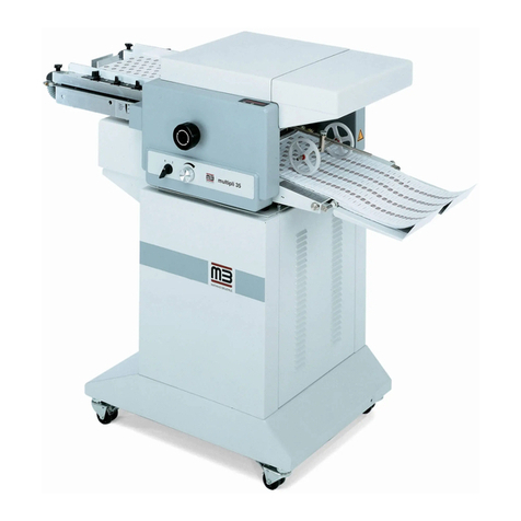
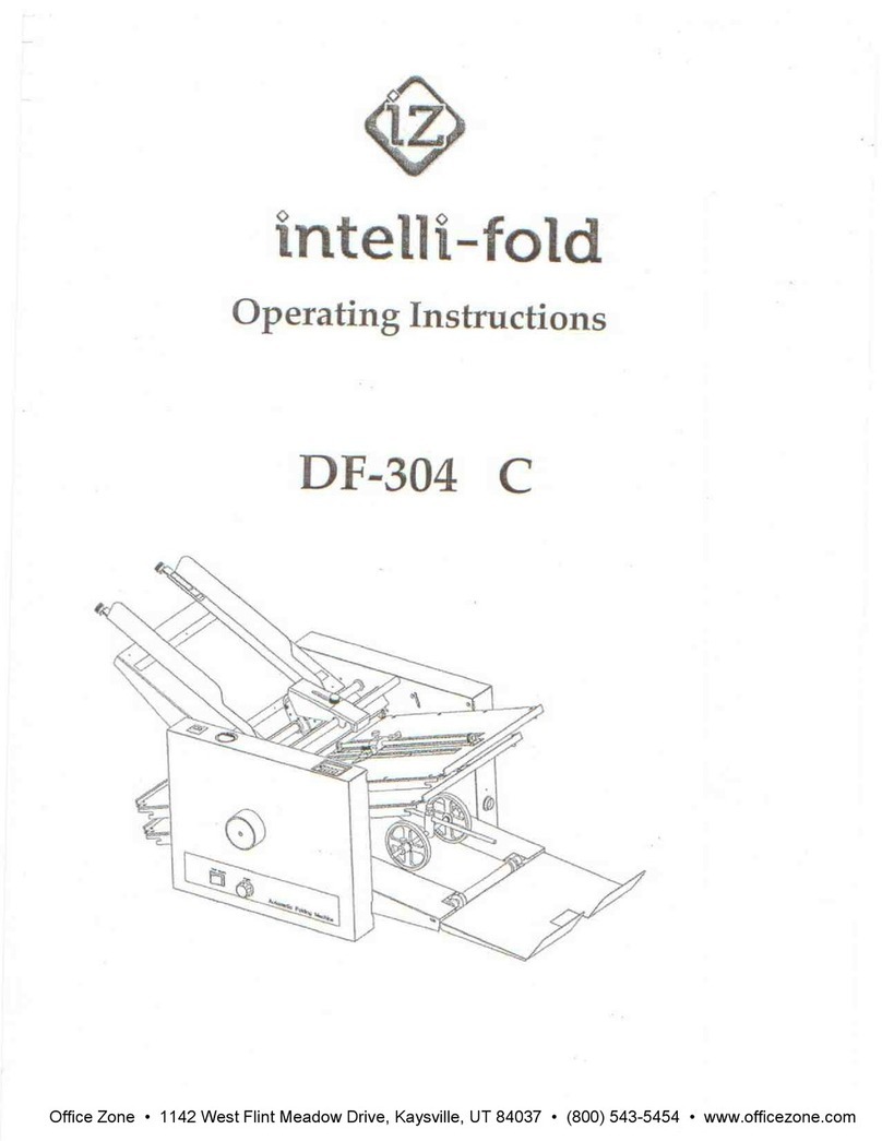
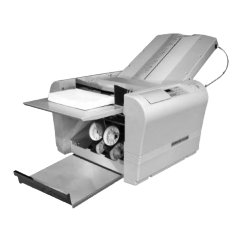
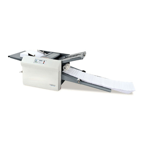
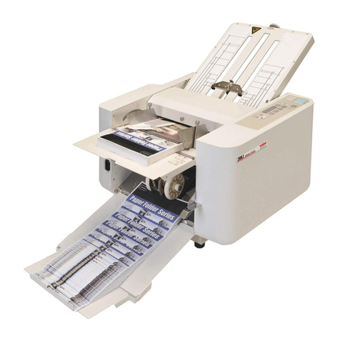
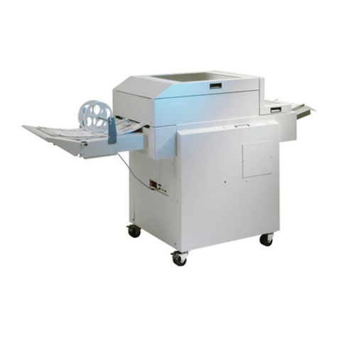
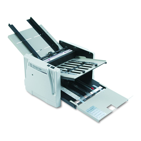
Horizon Fitness PF-P330 User manual

Page1/1
PF-P330 Revision Control List
Manual No. Date Bulletin Code S/N applied History Page
US503009-00 Oct/21/2003 First Edition
Dec/ 20/2003 1. Correcting the valve spring length 4-5
2.Changing the touch panel indication to icon from English 4-5, 5-6, 6-7
Mar/07/2004 1.Adding description about [All Memory Clear]. 2-2
Sep/17/2004 1.Adding side cover unit. 1-12
Sep/28/2004 007001- 1.Adding chapter 6-8 "PF-P330ROM Version Up History
"
6-11, 6-12
Sep/28/2004 014001-
1.Adding Main Control ROM V1.30 6-8 "PF-P330ROM Version Up
Histor
y
"6-11
A
pr/04/2005 017001- 1. Adding the air output adjusting function to the pump 1-11
US503009-00 Apr/17/2008 CD080079_00
E
045001-
1. Adding Main Control ROM V.1.50 in Section 6-8ROM Version U
p
History. 6-11


I
Important Information
This service manual is designed to help you to repair and maintain the PF-P330 in order to keep it in good operating condi-
tion. Please read and understand the instructions in this service manual before performing any repair or maintenance.
- Horizon International Inc. shall not be liable for incidental or consequential damages resulting from: improper or inadequate
maintenance by the customer; unauthorized modification or misuse; or operation outside of the environmental specifications
for the product.
- Horizon International Inc. follows a policy of continuing improvement in design and performance of the product. Therefore,
the product design and specifications are subject to change without prior notice and without our legal obligation.
- All rights are reserved. No part of the manual may be photocopied, reproduced or translated to another language without the
prior written consent of Horizon International Inc.
FOREWORD
Paper Folder PF-P330
US503009-01
080417/PFP330/01E/NO/HF/HO/P6.5/I9/P7

II
Safety Precautions
- Please read and understand all safety instructions with include the terms WARNING, and CAUTION. If these safety
instructions are ignored, personal injury may result.
- The repair, maintenance and safety instructions in this manual are valid only when the repair or maintenance work is performed
according to the procedures described in this manual.
- The term WARNING indicates a potentially hazardous situation which, if not avoided, could result in death or serious injury.
- The term CAUTION indicates a potentially hazardous situation which, if not avoided, may result in damage on machines. It may
also be used to alert against unsafe practices.
- Horizon International Inc. cannot anticipate every possible situation that might involve a potential hazard. The instructions in this
manual and the warning labels on the machine are therefore not all-inclusive.
- All equipment shall be locked out or tagged out to protect against accidental or inadvertent operation when such operation, repair
or maintenance could cause injury to personnel. Do not attempt to operate any switch, valve, or other energy isolating device
when it has been locked or tagged out.
- Some of the drawings in this manual show the machine uncovered for explanations of details inside the machine.

III
2. Abbreviations for electrical parts
Abbreviations
1. Abbreviations for wire colors
BRN = Brown
RED = Red
ORN = Orange
YEL = Yellow
GRN = Green
BRN(#) = the character (#) that follows the wire color indicates the
attached gray sticker. The sticker is to identify the wire in case there
are two wires of the same color.
RED/BLU = "/BLU"; the color that follows slash indicates the base
color of the wire. In this case, the wire is striped red on the blue color.
Axx = Inverter/Driver
Bxx = Sensor
Fxx = Fuse
Gxx = Power Supply
Kxx = Contactor
Lxx = LED
Mxx = Motor
Qxx = Circuit Protector/Breaker
QPM = (Multi Layer) P. C. Board
QPW = (Single Layer) P. C. Board
S/SWxx = Switch
Xxx = Terminal Board/Connector
Yxx = Solenoid/Clutch/Brake
R/VR = Volume
SL/SOL
= Solenoid
SSR = Solid State Relay
CON = Connector
DSW = Dip Switch
NF = Noise Filter
3. Other Abbreviations
BLU = Blue
VIO = Violet
GRY = Gray
WHT = White
BLK = Black

IV
P.C.Board and ROM can be damaged by humanly inperceptible static electricity.
Handle P.C.Board and ROM with following care.
Heading Precautions for P.C.Board and ROM
Do not put P.C.Board and
ROM on the machine,
especially on the acrylic cover.
(No problem on the conductive
plate.)
nd keep the P.C.Board and
ROM away from the insulators.
Insulators: Plastic, form polystyrene,
chemical fiber fabric, dry
paper, etc.
When replacing the P.C.Board
and ROM, or setting the dip
switches and volumes on the
P.C.Board, wear a wrist strap,
and connect the clip to the
machine frame (not painted
surface).
P.C.Board
Shield Bag
Keep P.C.Board in a
shield bag.
Put the ROM on a
conductive sponge
and keep in a shield
bag.
Shield Bag
Conductive
Sponge
crylic
Cover
Wrist
Strap
Clip
Machine
Frame

V
Contents
1. Mechanism
1-1 Feed Table Unit .......................................................................... 1-2
1-2 Table Up/Down Unit .................................................................. 1-3
1-3 Table Height Detect Unit............................................................ 1-4
1-4 Feed Rotor Unit .......................................................................... 1-5
1-5 Double Feed Stop Unit ............................................................... 1-6
1-6 Fold Roller Unit.......................................................................... 1-7
1-7 Deflector Unit ............................................................................. 1-8
1-8 Delivery Unit .............................................................................. 1-9
1-9 Buckle Chute Unit .................................................................... 1-10
1-10 Air Circuit Unit......................................................................... 1-11
1-11 Side Cover Unit ........................................................................ 1-12
2. Service Mode
2-1 Operations of Service Mode ....................................................... 2-2
2-2 Calibrating the Home Position (Buckle Chute Stopper) ............ 2-3
3. Adjusting and Checking Procedures
3-1 Sheet Guides Right Angle and Parallel Adjustment................... 3-2
3-2 Rack and Pinion Position Adjustment ........................................ 3-3
3-3 Lower Guide and Fold Roller Gap Adjustment ......................... 3-4
3-4 Deflector Position Adjustment ................................................... 3-5
3-5 Buckle Chute Stopper Level Adjustment ................................... 3-6
3-6 Belt Tension Adjustment ............................................................ 3-7
3-7 Stopper (Roller Lever) Position Adjustment .............................. 3-8
3-8 Table Upper Limit Switch S01 Position Adjustment ................. 3-9
3-9 Feed Rotor Check ..................................................................... 3-10
3-10 Feed Ring Replacement ............................................................ 3-11
4. Mechanical Troubleshooting
4-1 Error Code 01 Is Indicated (= Feed Table Does Not Lower) ..... 4-2
4-2 Error Code 02 Is Indicated (= Feed Table Does Not Lift) ......... 4-3
4-3 Buckle Chute Sounds Loudly and Q01/02 Are Actuated ........... 4-4
4-4 Feed Rotor Does Not Suction the Sheets ................................... 4-5
4-5 Feed Rotor Does Not Drive ........................................................ 4-6
4-6 Fold Rollers Do Not Rotate ........................................................ 4-7
4-7 Delivery Conveyor Belt Does Not Drive ................................... 4-8
4-8 Deflector Malfunctions ............................................................... 4-9
4-9 Buckle Stopper Does Not Move ............................................... 4-10
4-10 Motor Does Not Drive .............................................................. 4-11
4-11 Display Does Not Show Any Image ........................................ 4-13
4-12
Error Message “Close Buckle” Is Shown (Even though it is closed)
4-14

VI
5. Folding Quality Troubleshooting
5-1 Wrinkled Sheets.......................................................................... 5-2
5-2 Folded Corners ........................................................................... 5-3
5-3 Sheet Edges Do Not Align ......................................................... 5-4
5-4 Sheet Is Folded Askew ............................................................... 5-5
5-5 Sheets Are Not Arranged On the The Delivery.......................... 5-6
5-6 Sheet Jams at the Deflector ........................................................ 5-7
6. Electrical Circuit
6-1 Electrical Parts Leyout and Descripton ...................................... 6-2
6-2 Electrical Chassis Layout and Description ................................. 6-3
6-3 P.C.B. Layout and Description ................................................... 6-4
6-4 Control P.C.B. QPM-192 ........................................................... 6-5
6-4-1 QPM-192 P.C.B. Layout ............................................ 6-5
6-4-2 QPM-192 LED Layout .............................................. 6-6
6-5 LCD P.C.B. QPW-677 ............................................................... 6-7
6-6 24V/5VDC Wiring Diagram ...................................................... 6-8
6-6-1 Buckle Chute Section ................................................. 6-8
6-6-2 Main Section ............................................................... 6-9
6-7 Power Circuit Wiring Diagram ................................................ 6-10
6-8 PF-P330 ROM Version Up History ......................................... 6-11

1
1-1
1: Mechanism
Mechanism
1. Mechanism

1-2
1: Mechanism
1-1 Feed Table Unit
Sheet Guide
Window for Sensor
Feed Angle
Adjusting Mechanism
The sheet guides rotate
on this fulcrum.
Guide Shaft
Eccentric Rod
Link
This rod is eccentric.
Feed Angle Adjusting Mechanism
1 2
Angle is adjustable
within the range of
this square.
Nut Plate
Slide Bracket
Sheet Guide
Fulcrum
Screw
Adjusting
Screw
Sheet Guide
Fixing Knob
The screw works as
the fulcrum of
sheet guide angle.
Sheet Guide Angle Adjusting Mechanism

1
1-3
1: Mechanism
Mechanism
1-2 Table Up/Down Unit
Bearing
Rack (front)
Pinion
Joint
Rack (rear)
Side Plate
(front)
Side Plate (rear)
Guides
Table Fixing Hole
Pinion Pinion
Top View
Joint
Table Up/Down Motor
M02
1-2: Table Up/Down Unit
Pinion
Guides
Table Bracket
(Rack)
Side View

1-4
1: Mechanism
1-3 Table Height Detect Unit
H
O
L
L : Table Height Low
O : Table Height Standard
H : Table Height High
Height Detecting Bar
Sensor
B06
When the top of the loaded
sheets pushes up this bar,
the sensor detects the metal
attached on the back of the bar.
Fulcrum for both
Fulcrum
Height Detecting Bar
Adjusting Lever
Adjusting Lever

1
1-5
1: Mechanism
Mechanism
1-4 Feed Rotor Unit
Vacuum Pipe
This pipe does not rotate.
This suctions the air through
the holes at the bottom.
Vacuum Rotor
This ring rotates and
suctions the sheet
through the radial slits.
Vacuum Rotor
Feed Ring
Vacuuming Mechanism
Clutch
Electromagnetic
Valve
A
Vacuum
Rotor Unit
Vacuuming Mechanism
Fold Rollers
Drive Motor
M01
Driving Mechanism Viewing from A
1-4: Feed Rotor Unit

1-6
1: Mechanism
1-5 Double Feed Stop Unit
Double Feed
Prevention Unit
Gate Lever
Blowing Outlet
Blower (exhale)
Square Pipe
The double feed stop unit
moves Up/Down on this fulcrum.
Double Feed Stop Plate
Moves Up/Down within
the range of this slot.
Fulcrum
Gate Lever
Gate Plate
Urethane
When installing the
gate plate, push it
down and screw it.
Up/Down Slide Plate
The bending and friction of this urethan
prevents the double feeding of the sheets.
Gate Plate
Urethan
Vacuum Roller
Worn out
When the flat
disappears, replace
to a new one.

1
1-7
1: Mechanism
Mechanism
1-6 Fold Roller Unit
1
24
35
4
Vacuum Rotor
The gap between the first roller and guide plate
= 1 mm (0.04")
Remove the second and fourth rollers.
After removing the rollers, raise the buckle
fixing lever and reset the roller lever level.
(If the buckle fixing lever is left lowered, the roller
lever pushes the guide plate up.)
Insert an 1 mm (0.04") allen wrench from the
infeed side, and check the gap.
1
2
Roller Lever Guide Plate
1mm
(0.04")
Solenoid ON = When the deflector is Up.
-
When the solenoid turns ON, the deflector
goes up and closer to the third roller.
- The sheet that comes through the second
and third roller goes under the deflector and
is delivered. (As shown with the arrow to
the right.)
Solenoid OFF = When the deflector is Down.
- When the solenoid turns OFF, the deflector
lowers and makes a space between the
deflector and the third roller.
- The sheet that comes through the second
and third roller goes over the deflector, then
goes to the second buckle chute through
the third and fourth roller.
24
3
24
3
Buckle
Chute
Side
1
2
3
[CHECK]
1-6: Fold Roller Unit

1-8
1: Mechanism
1-7 Deflector Unit
Deflector Unit
Deflector
Deflector Lever (front)
Deflector Holder
Deflector
Side Plate
Lock the deflector with this screw.
Solenoid ON:
Adjust the tilt of the deflector by
adjusting the deflector holder with
these two screws.
Deflector
Fulcrum Shaft
Deflector Lever
Deflector Holder
Solenoid OFF:
The upper/lower limit of the
deflector is decided by the
15 hole on the side plate.
15 hole
on the side plate

1
1-9
1: Mechanism
Mechanism
1-8 Delivery Unit
The O ring contacts the shaft directly
and drives the delivery shaft.
(The motor does not have reduction gear.
This wheel makes large reduction ratio.)
Adjust the belt tension
by fixing the shaft within
the range of the slot.
O Ring
M01
Delivery Belt
Tension Adjustment of the Delivery Belt
Drive Motor
1-8: Delivery Unit

1-10
1: Mechanism
1-9 Buckle Chute Unit
Buckle Chute Unit
Encoder
Sensor Sensor
Plate
Encoder Unit
B01
Home Position
Sensor
Sensor Plate
Screw Shaft Drive Gear
Idle Gear
M03
M04
Motor Gear
Stopper
Stopper Drive Mechanism

1
1-11
1: Mechanism
Mechanism
IN
OUT
- Inside the box, the motor M05 is installed.
- The air comes from top goes out through
the coil of the motor. The coil is also cooled
down by the air blow.
Carbon Brush
The carbon
worn out
Blower Box
M05
Blower Motor
Electromagnetic
Valve
Open/Close
Vacuum Air
Vacuum Rotor
This ring rotates and
suctions the sheet
through the radial slits.
Vacuum Plug
Separation Air Outlet
Separates the suctioned top
sheet from the rest of the sheets.
Blower Air Outlet
Blows the top of the loaded sheets
and flips it up.
1-10 Air Circuit Unit
1-10: Air Circuit Unit
[CAUTION]
The carbon brush can not be replaced
singly. Replace the whole blower box.

1-12
1: Mechanism
1-11 Side Cover Unit
L
L
0
H
H
LH
CAUTION
Do not remove the side covers forc-
ibly. Otherwise, the cover may be
damaged. Delivery side of the cover
is hooked into the side frame as
shown in the illustration to the right.
Side Cover (Front/Rear) Removal
Remove the lock screws (two on each
side).
Loosen the lock screw of the anel.
(See the illustration to the left.)
- Do not remove the screw. Loosen it until the anel
becomes shaky.
Insert the screw driver at the bottom.
- Insert the small screw driver at the bottom of the cover
(at arrow showing osition) and lift the cover u .
- Insert and lift in the numbering order.
Insert the screw driver at the arrow
showing osition.
- Insert the screw driver at the bottom and lift the cover,
then ull the covers outward.
FrontCover
Panel
[View from the
delivery side]
Rear Cover
Loosen
Remove the
lock screw.
Loosen
Front Cover
Insert the screw
driver here.
Front cover is fit
to this rojection.
Part Description and Structure
123
Table of contents
Other Horizon Fitness Folding Machine manuals

Horizon Fitness
Horizon Fitness SPF-10 User manual

Horizon Fitness
Horizon Fitness PF-P320 User manual

Horizon Fitness
Horizon Fitness AFC-566F User manual

Horizon Fitness
Horizon Fitness H-1000XP User manual

Horizon Fitness
Horizon Fitness SPF-10 User manual

Horizon Fitness
Horizon Fitness SPF-10II User manual

Horizon Fitness
Horizon Fitness PF-P3100 User manual

Horizon Fitness
Horizon Fitness PF-P3100 User manual

Horizon Fitness
Horizon Fitness SPF-20A User manual

Horizon Fitness
Horizon Fitness CRF-362 User manual