upelUIIUII
IVIUIIUUJ
MtiU,!
I
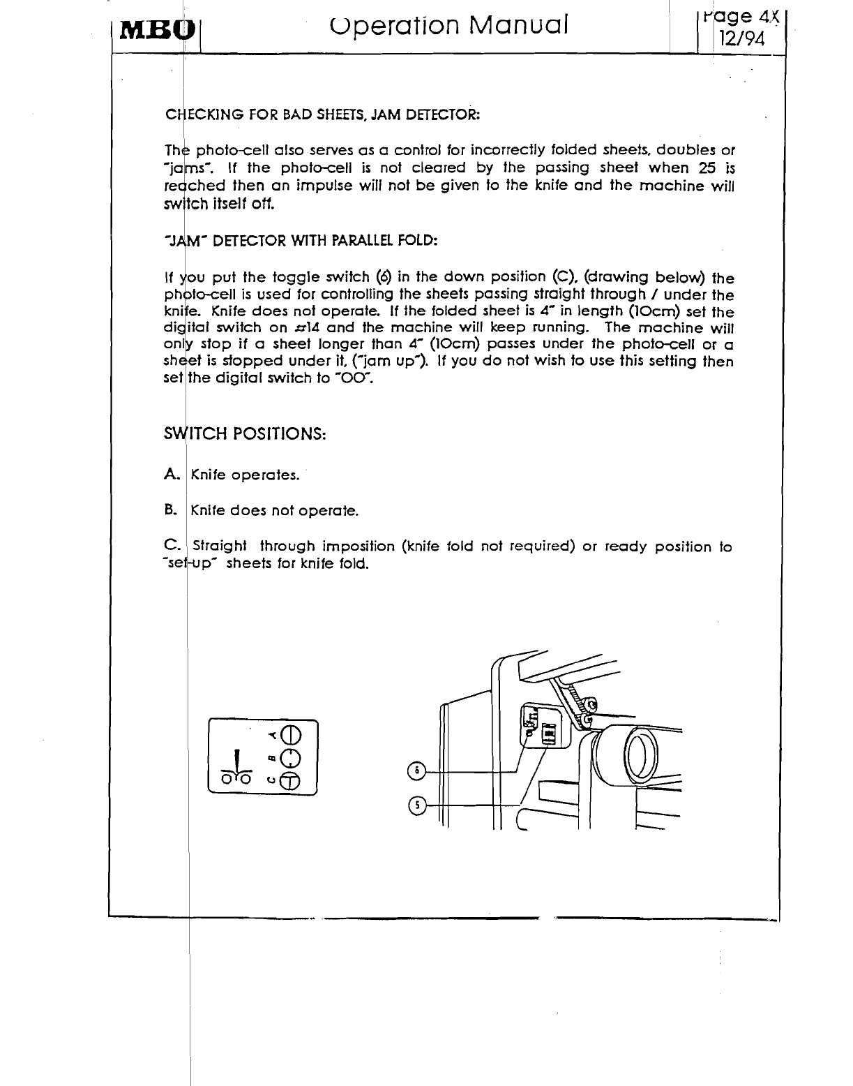
The
"x"
knife unit I
The
new
self-timing knife folding A unit
can
be
used
either
attached
to
fh~
pare lief
folding
unit as a 8
page
seCtion
or
to the 8
page
second
unit
after
the
fold plate:;.
T~e
folding
~olJers
and
knife shafts
as
well
as
!he
elec.tric clu.tch
~I
r
the
knife
mahan
are
dnven
by
a belt from the
preceding
folding
umt.
Th
electric
supply
to
the
clutch
a:; well as the
electronic
control:;
are
made
y
cab
e connections. The fold roller perforator shaft adjustments
are
made
cit
the
pperators
side
by
caliper
settings. Four transport
tapes
(8)
move
the
she,t
to
It
e sheet stops (7).
which
is
adjusted
according
to
the
scale
at
the
left
side
of
tt
e
machine
(2). In
accordance
to the sheet
size
use sufficient stop fingers
(7) (
ffached
to
the
sheet stop
bar
(1).
For
the final po:;itioning
of
the
sheet
the
side
guides
(6),
have
to
be
set.
one
on
each
side. The
height
of
the
foldin,6
knifl
(31)
can
be
adjusted
by
the
handle
(32)
:;ituated on
the
top
of
the
c1utqh
asse
mbly.
Turning
the
handle
COUNTER
ClOCKWISE moves
the
knife
nearer
to
the
oilers.
CLOCKWISE
moves it farther aV!ay. The knife
may
also
be
mov~d
hori ontaly,
(perpendicular
to the fold rollers) (tips
the
knife
from
front to
bacl¢.
Thi
operation
is
done
by
turning
handle
(33).
It
may
be
necessary to adju'st
the
~nife
to
correct
a
·crooked·
perforator I knife cut. i
I
I
The slitter shafts
und~r
the
fold rollers
can
be.
removed
by
means
of
pl~g
bee rings like in
the
other
folding units. i
I
The stacker I
delivery
is
positioned tacing the operator. (operators side). I
If the -X- unit
is
used on
the
8
page
unit the sheet
MUST
always
run in
the
cent~r
of
he
8
page
unit.
(if
a
half
fold
is
processed).
For
that
purpose
a conveypr
syst~m
is
used
with
yellow
belts I tapes to convey the sheet
to
the
center
aryd
under
the
side
lay.
This
unit
is
attached
to the
parallel
unit
by
-hooks·
arid
lac
ing screws. When running a
large
sheet the 8
page
unit
MUST
be
mov~d
awCJY
from
the
parallel
unit.
This
will
enable
the tail
of
the
sheet to
clear
t~e
conveyo~
: