1.Technical Data
Model
Free speed
Torque Dimension
LWeight
Air Consumption
Air Inlet Inner Hose
Dia.
Sound pressure
LpA
Sound power
LwA
Vibrations
Min Max Free speed ahd K
1 2 3 4 5 6 7 8 9 10 11
[min-1] [Nm] [Nm] [inch]
[mm]
[kg]
[lb]
[l/min]
[SCFM] [inch] [inch]
[mm] [dB(A)] [dB(A)] [m/s²] [m/s²]
max. pressure 6.3bar(90psi)
ah: Vibration level, kUncertainty ; LpA Sound pressure dB(A), KpA = KWA = 3 dB Uncertainty.
Declaration of noise and vibration statement (ISO 15744 and ISO 28927-2)
All values are current as of the date of this publication.
These declared values were obtained by laboratory type testing in accordance with the stated standards and are suitable for comparison with the declared
values of other tools tested in accordance with the same standards. These declared values are not adequate for use in risk assessments and values measured
in individual work places may be higher. The actual exposure values and risk of harm experienced by an individual user are unique and depend upon the way
the user works, the workpiece and the workstation design, as well upon the exposure time and the physical condition of the user. We, CHICAGO PNEUMATIC
TOOLS , cannot be held liable for the consequences of using the declared values, instead of values reecting t he a ctual e xposure, i n a n i ndividual risk
assessment in a work place situation over which we have no control. This tool may cause hand-arm vibration syndrome if its use is not adequately
managed. We recommend a programme of health surveillance to detect early symptoms which may relate to noise or vibration exposure, so that management
procedures can be modified to help prevent future impairment.
2. Machine type(s)
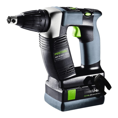
• This product is designed for installing and removing threaded fasteners in wood, metal and plastic.No other use permitted. For professional use only.
• Please read the instructions carefully before starting the machine.
3. Operation (See gures)
• Fix the accessories properly to the tool.
• Connect device as shown in Fig. 01.
• To start the machine, pull the trigger (A). Machine speed is increase by increasing pressure on the trigger. Release the trigger to stop.
• Use the reverse switch (B) only when the drive spindle comes to a complete stop. Changing the speed before the drive spindle stops may damage the
machine.
• To switch rotation, turn the switch (B) as shown in Fig. 03.
4. Lubrication
Motor Clutch
Use an air line lubricator with SAE #10 oil, adjusted to two drops per minute. If an air line
lubricator cannot be used, add air motor oil to the inlet once a day.
Use Molykote BR2PLUS or equivalent grease. [14 oz (395 g)]
5. Maintenance instruction
• Follow local country environmental regulations for safe handling and disposal of all components.
• Maintenance and repair work must be carried out by qualified personnel using only original spare parts. Contact the manufacturer or your nearest authorised
dealer for advice on technical service or if you require spare parts.
• Always ensure that the machine is disconnected from energy source to avoid accidental operation.
• Disassemble and inspect the tool every three 3 months if the tool is used every day. Replace damaged or worn parts.
• High wear parts are underlined in the parts list.
6. Disposal
• The disposal of this equipment must follow the legislation of the respective country.
•All damaged, badly worn or improperly functioning devices MUST BE TAKEN OUT OF OPERATION.
• Repair only by technical maintenance staff.
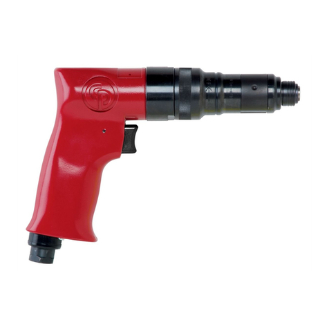
CP783
Screwdriver
7. EC Declaration of conformity
Machine type(s): Screwdriver
Declare that the product(s): CP783 Serial Number: 001 - 999
Origin of the product : JAPAN
is in conformity with the requirements of the council Directives on the approximation of the laws of the Member States relating : to “Machinery“ 2006/42/EC applicable
harmonised standard(s) : EN ISO 11148-6:2012
Name and position of issuer : Pascal Roussy (R&D Manager)
Check out the collection of air drills and drivers we offer.
