CHIEF PACPC1 User manual

INSTALLATION INSTRUCTIONS
Instrucciones de instalación
Installationsanleitung
Instruções de Instalação
Istruzioni di installazione
Installatie-instructies
Instructions d´installation
Power Conditioner Accessory
Spanish Product Description
German Product Description
Portuguese Product Description
Italian Product Description
Dutch Product Description
French Product Description
PACPC1

PACPC1 Installation Instructions
2
DISCLAIMER
CSAV, Inc., and its affiliated corporations and subsidiaries
(collectively, "CSAV"), intend to make this manual accurate and
complete. However, CSAV makes no claim that the information
contained herein covers all details, conditions or variations, nor
does it provide for every possible contingency in connection
with the installation or use of this product. The information
contained in this document is subject to change without notice
or obligation of any kind. CSAV makes no representation of
warranty, expressed or implied, regarding the information
contained herein. CSAV assumes no responsibility for
accuracy, completeness or sufficiency of the information
contained in this document.
IMPORTANT WARNINGS AND
CAUTIONS!
WARNING:
A WARNING alerts you to the possibility of
serious injury or death if you do not follow the instructions.
CAUTION:
A CAUTION alerts you to the possibility of
damage or destruction of equipment if you do not follow the
corresponding instructions.
WARNING:
Failure to read, thoroughly understand, and
follow all instructions can result in serious personal injury,
damage to equipment, or voiding of factory warranty! It is the
installer’s responsibility to make sure all components are
properly assembled and installed using the instructions
provided.
WARNING:
Failure to provide adequate structural strength
for this component can result in serious personal injury or
damage to equipment! It is the installer’s responsibility to
make sure the structure to which this component is attached
can support five times the combined weight of all equipment.
Reinforce the structure as required before installing the
component.
WARNING:
Exceeding weight capacity can result in
serious personal injury or damage to equipment! It is the
installer’s responsibility to make sure the combined weight of
all components does not exceed the maximum allowable
weight of the mount to which this accessory is being installed.
DIMENSIONS
Measurements in: inches
[
millimeters]

Installation Instructions PACPC1
3
LEGEND
Tighten Fastener
Apretar elemento de fijación
Befestigungsteil festziehen
Apertar fixador
Serrare il fissaggio
Bevestiging vastdraaien
Serrez les fixations
Loosen Fastener
Aflojar elemento de fijación
Befestigungsteil lösen
Desapertar fixador
Allentare il fissaggio
Bevestiging losdraaien
Desserrez les fixations
Security Wrench
Llave de seguridad
Sicherheitsschlüssel
Chave de segurança
Chiave di sicurezza
Veiligheidssleutel
Clé de sécurité
By Hand
A mano
Von Hand
Com a mão
A mano
Met de hand
À la main
PACPC1 Installation Instructions
4
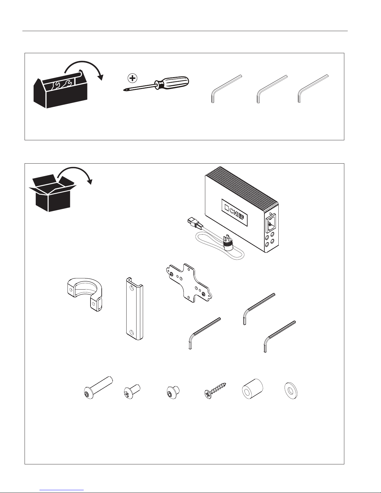
TOOLS REQUIRED FOR INSTALLATION
PARTS
5/32"
3/32"
Security
(Provided)
5/32"
Security
(Provided) (Provided)
A (1)
(includes cord)
B (1)
C (1)
E (1)
3/32"
(Security)
F (1)
5/32"
(Security)
G (1)
5/32"
H (2)
1/4-20 x 1-1/4"
J (1)
8-32 x 3/8" K (2)
1/4-20 x 1/4"
L (2)
#6 x 1"
M (2)
.625x.312x.750
N (4)
1/4"
D (1)

Installation Instructions PACPC1
5
INSTALLATION
Attaching to Drywall
1. Attach bracket (D) to drywall using two #6 x 1" drywall
screws (L). (See Figure 1)
NOTE:
Do NOT overtighten drywall screws.
2. Proceed to Installing Conditioner.
Figure 1
Attaching to Wood Stud
1. Drill two 0.08" pilot holes into wood stud. (See Figure 2)
2. Attach bracket (D) to wall using two #6 x 1" drywall
screws (L).
3. Proceed to Installing Conditioner.
Figure 2
Attaching to 1-1/2" NPT Pole
1. Attach bracket (D) to pole mount bracket (C) using two
1/4-20 x 1/4" buttonhead screws (K). (See Figure 3)
NOTE:
The bracket can be installed for either horizontal or
vertical attachment of the conditioner. (See Figure 3)
Figure 3
2. Attach pole clamp (B) around the pole to the pole mount
bracket using two 1/4-20 x 1-1/4" buttonhead security
screws (H), four 1/4" washers (N), and two spacers (M).
(See Figure 4)
Figure 4
(D)
(L) x 2
Wood
Stud
Wall
(D)
(L) x 2
1
2
(K) x 2
(C)
(D)
Conditioner to be Attached Horizontally
Conditioner to be Attached Vertically
(B)
(M) x 2
(H) x 2
(N) x 4
1-1/2" NPT Pole
(Horizontal Attachment Shown)
PACPC1 Installation Instructions
6
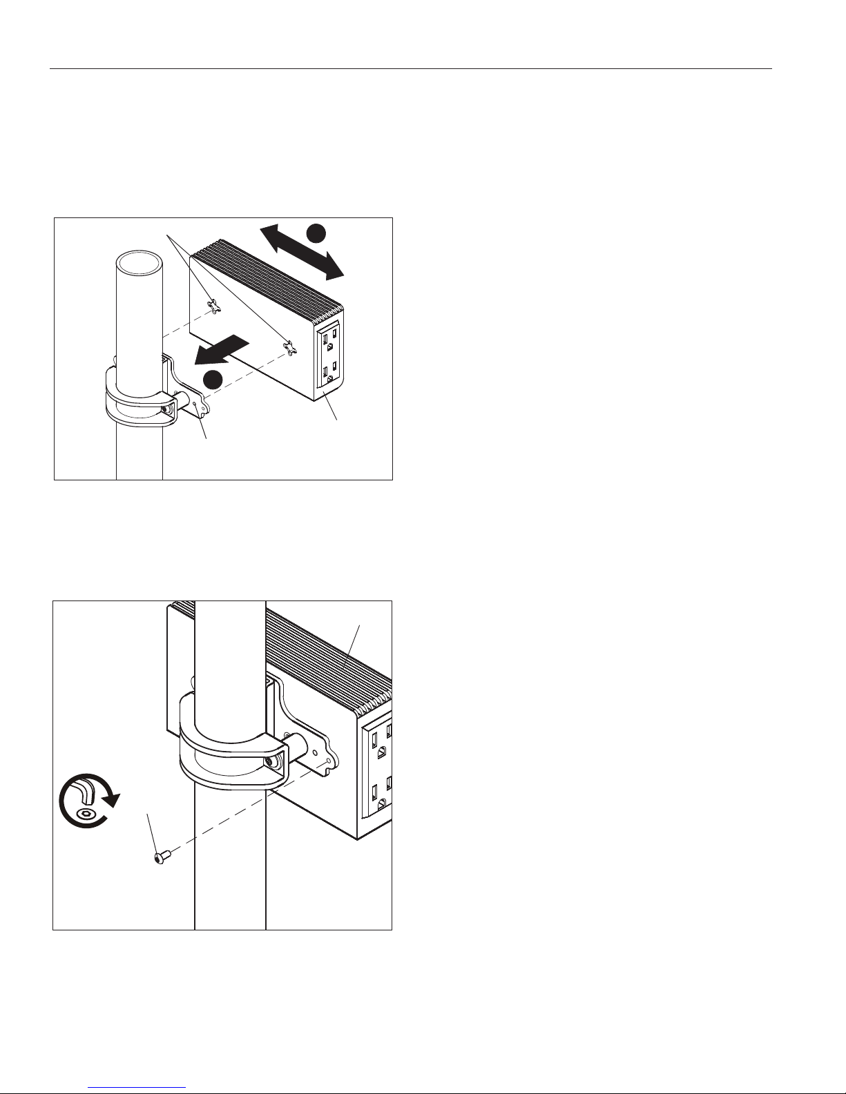
Installing Conditioner
1. Insert conditioner slots onto Phillips screws in bracket.
(See Figure 5)
2. Slide conditioner left or right. (See Figure 5)
3. Remove conditioner to adjust Phillips screws in bracket as
necessary for desired tension in mount.
Figure 5
4. OPTIONAL: For additional security, insert and tighten one
8-32 x 3/8" buttonhead security screw (J) through the
bracket into the conditioner. (See Figure 6)
NOTE:
Use optional security screw in pole mount application
only.
Figure 6
1
2
(Pole mount shown)
Conditioner
Bracket
Screws (x 2)
Conditioner
Slots
(J) x 1
Conditioner
(Horizontal Attachment Shown)

PACPC1 Installation Instructions
USA/International A 8401 Eagle Creek Parkway, Savage, MN 55378
P800.582.6480 / 952.894.6280
F877.894.6918 / 952.894.6918
Europe A Fellenoord 130 5611 ZB EINDHOVEN, The Netherlands
P31 (0)20 5708923
F31 (0)20 5708989
Asia Pacific A Room 30I, Block D, Lily YinDu International Building
LuoGang, BuJi Town, Shenzhen, CHINA. Post Code: 518112
P+86-755-8996 9226 ; 8996 9236 ; 8996 9220
F+86-755-8996 9217
8832-000240
¤2007 Chief Manufacturing
www.chiefmfg.com
09/07
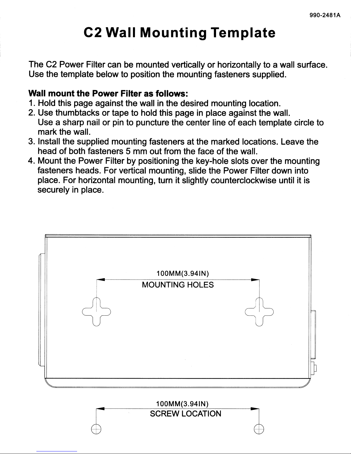
990-2481A
C2 Wall
Mounting
Template
The C2 Power Filter can be mounted vertically
or
horizontally to a wall surface.
Use the template below to position the mounting fasteners supplied.
Wall mount the Power Filter as follows:
1.
Hold this page against the wall in the desired mounting location.
2.
Use thumbtacks
or
tape to hold this page
in
place against the wall.
Use a sharp nail or pin to puncture the center line
of
each template circle to
mark the wall.
3.
Install the supplied mounting fasteners at the marked locations. Leave the
head
of
both fasteners 5 mm out from the face
of
the wall.
4.
Mount the Power Filter by positioning the key-hole slots over the mounting
fasteners heads. For vertical mounting, slide the Power Filter down into
place. For horizontal mounting, turn it slightly counterclockwise until it is
securely
in
place.
1OOMM(3.941N)
I - MOUNTING HOLES
!
~
l
1OOMM(3.941N)
SCREW LOCATION
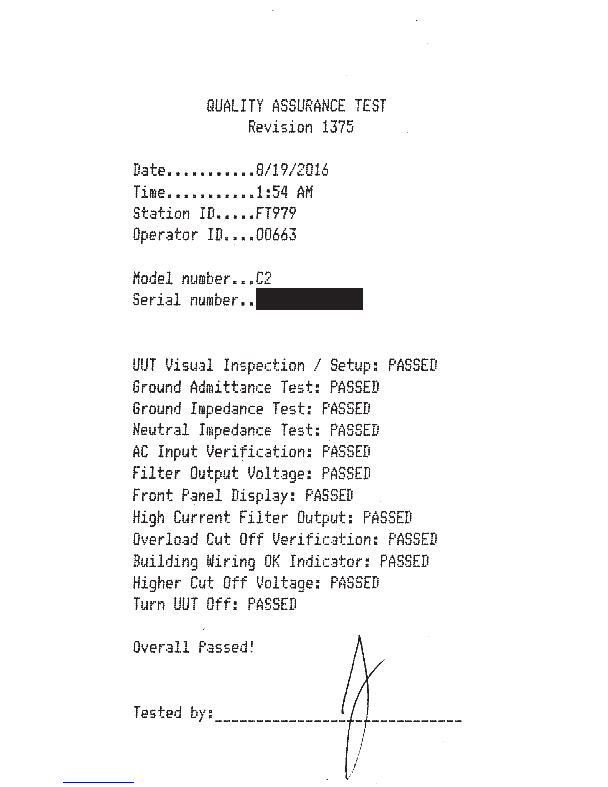
QUALITY
ASSURANCE
TEST
Revision
1375
n t
8
1
~9'~01'
.Li-3
.e....... .... , 1 .
1.::.
t:
Time
•••••••••••
1:54
AM
Station
ID
•••••
FT979
Operator
ID
••••
00663
Model
number
•••
C2
Serial
number
••
UUT
Visual
Inspection I
Setup:
PASSED
Ground
Admittance
Test:
PASSED
Ground
Impedance
Test:
PASSED
Neutral
Impedance
Test:
rASSED
AC
Input Verification:
PASSED
Filter
Output
Voltage:
PASSED
Front
Panel
Displ.3y:
PASSED
High
Current
Filter
Output:
PASSED
Overload
Cut
Off
Verification:
PASSED
Building
Wiring
OK
Indicator:
PASSED
Higher
Cut
Off
Voltage:
PASSED
Turn
UUT
Off:
PASSED
Tested
by:
_________________
-----------

WARNING:
Downtime
puts
valuable
equipment
at
risk! Register
today
for
crucial
upgrade/replacementalerts.
ATTENTION:
Les
temps
d'arret
representantun risque
pour
votre
equipement
critique! lnscrivez-vousdes
aujourd'hui
pour
recevoirles alertes
de
misea
niveauou
de
remplacement.
ADVERTENCIA:
Los
tiempos
de
inactividadponenen riesgo
losequipos. Regfstrese hoy
mismo
para
recibir
importantes
alertassobre
actualizacionesfsustituciones.
Table of contents
Other CHIEF Accessories manuals

CHIEF
CHIEF KSA-1022 User manual

CHIEF
CHIEF CM4S57 User manual

CHIEF
CHIEF NPT Threaded Coupler Accessory CMA-152 User manual

CHIEF
CHIEF PAC780 User manual

CHIEF
CHIEF WMA2S User manual

CHIEF
CHIEF DGP32 User manual

CHIEF
CHIEF Fusion Mobile Carts & Stands User manual

CHIEF
CHIEF Keyboard Tray Accessory KSA1021 User manual

CHIEF
CHIEF Pole Clamp Accessory FSA-1017 User manual

CHIEF
CHIEF SLBU User manual


