CHIEF RPA145 User manual
Other CHIEF Rack & Stand manuals

CHIEF
CHIEF PAC-710 User manual

CHIEF
CHIEF K1D100 User manual

CHIEF
CHIEF PAC730A User manual

CHIEF
CHIEF FSA-1005 User manual

CHIEF
CHIEF STLU User manual

CHIEF
CHIEF MSP-WRTS1 User manual

CHIEF
CHIEF WMAC16 User manual

CHIEF
CHIEF TS218SU User manual

CHIEF
CHIEF CMA440 User manual

CHIEF
CHIEF RPA Series User manual

CHIEF
CHIEF FCAX08 User manual

CHIEF
CHIEF PSMO2085 User manual

CHIEF
CHIEF PAC-390 User manual

CHIEF
CHIEF PSM-2051 User manual

CHIEF
CHIEF QMP1MM2 User manual

CHIEF
CHIEF SSB-311 User manual

CHIEF
CHIEF PAC717 User manual

CHIEF
CHIEF SSB-257 User manual

CHIEF
CHIEF KRAMS K1W110 User manual

CHIEF
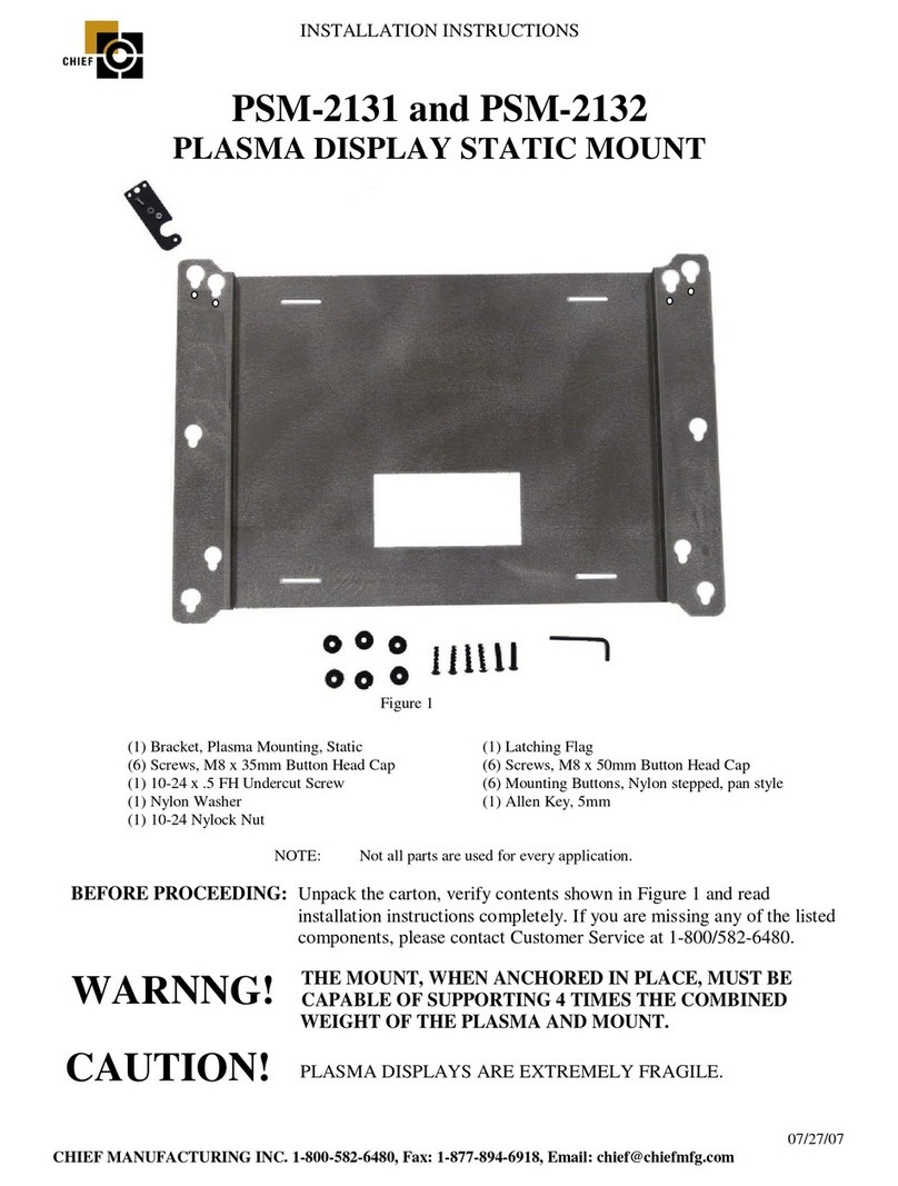
CHIEF PSM-2131 User manual
Popular Rack & Stand manuals by other brands

Salamander
Salamander Acadia AC/W/L400/WH Assembly instructions

Fohhn
Fohhn VAT-09 Mounting instruction

ricoo
ricoo FS0522 quick start guide

AMSOIL
AMSOIL BMK-22 Installation and service instructions

Kargo Master
Kargo Master 48220 installation guide

Milestone AV Technologies
Milestone AV Technologies SIMPLICITY SLF2 installation instructions


