Chigo CKST-4SH User manual
MODEL:CKST-4SH

24
19
20
2
++
X4
Expansion screws:
Install it on the four points of the bottom
plate to fix the unit to the foundation.
Signal wire
It is used for connecting the controller
to the unit
X2
1
2
3
4
780mm
258mm 540mm

4
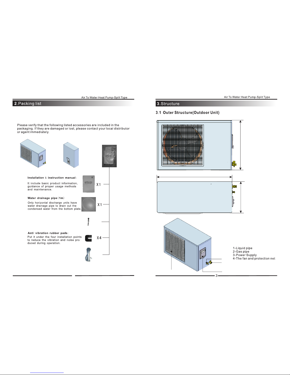
3.2 Outer Structure(Intdoor Unit)
1-Controller
2-Water Outlet
3-
4-
5-
6-Gas pipe
Liquid pipe
Water Inlet
Over the line hole
185mm
455mm
605mm
4.Specifications
Model CKST-4SH
Voltage/Phase/frequency 220V/1PH/50HZ
Amps Per Phase 5.0Amps
Min.Circuit Size 6.5Amps
Heating Capacity 4.0KW
Heating Power Input 1.1KW
Heating COP※4.2
Noise Level 48dB(A)@3m
Type Rotary
Number Per Unit 1
FLA(Full Load Amp) 5.5Amps
Voltage/Phase 220-240V/1PH
Type Propeller
Number Per Unit 1
Power Input 0.2KW
Voltage/Phase 220~240V/1PH
Fan Speed 720Rmp
Type Plate Type Heat Exchanger
Water Flow Volume (m^3/h) 0.8
Max.Outlet Water Temp 55℃
Water Connection 3/4Inch
Refrigerant R410A
Defrost Automatic Hot Gas Injection
Shipping weight Outdoor Unit:70kg;Intdoor Unit:18kg
Dimension L x W x H (mm) Outdoor Unit:780*258*540
Intdoor Unit:455*185*605
※※Heating: Outdoor Air Temp:15℃ DB ,11℃WB, Water Temp: 35℃
※Heating: Outdoor Air Temp:7℃ DB ,6℃WB, Water Temp: 40℃
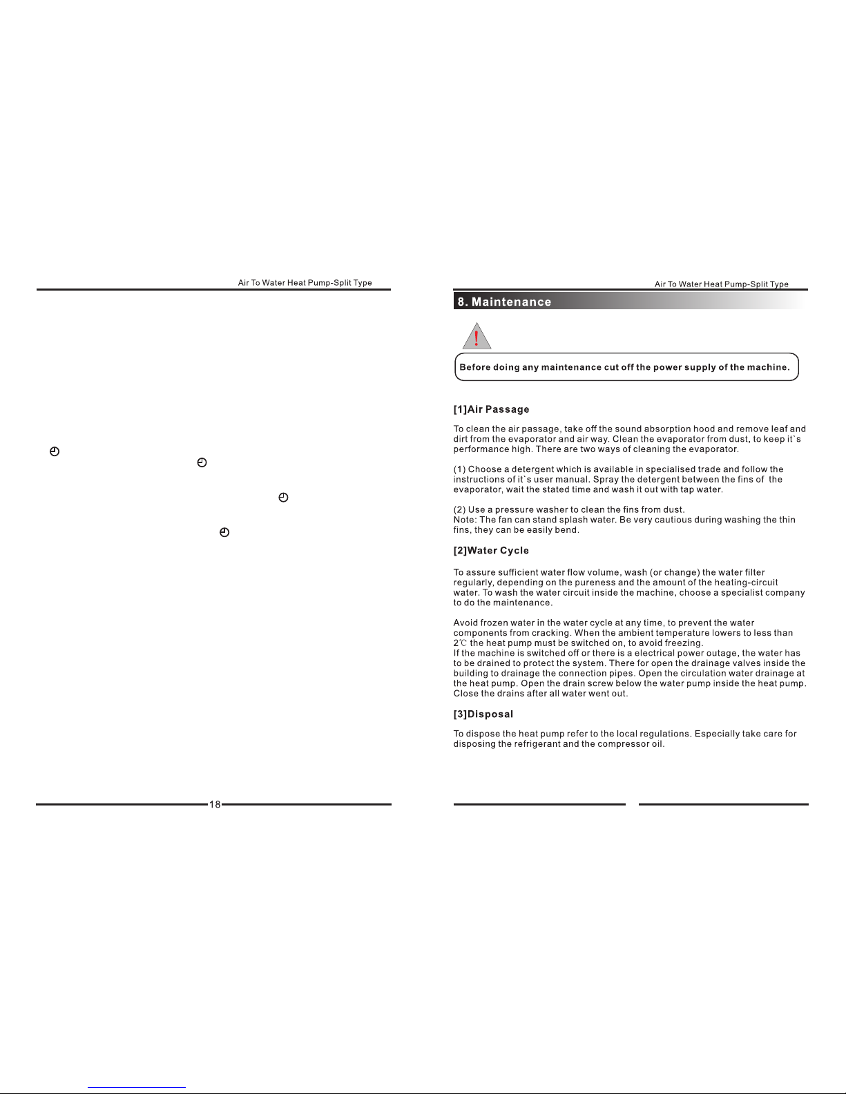
GENERAL INFORMATION
HEAT EXCHANGER(Water Side)
AIR TO WATER HEAT PUMP-SPLIT TYPE
Fan
Compressor
PERFORMANCE
ELECTRICAL INPUT
TECHNICAL DATA

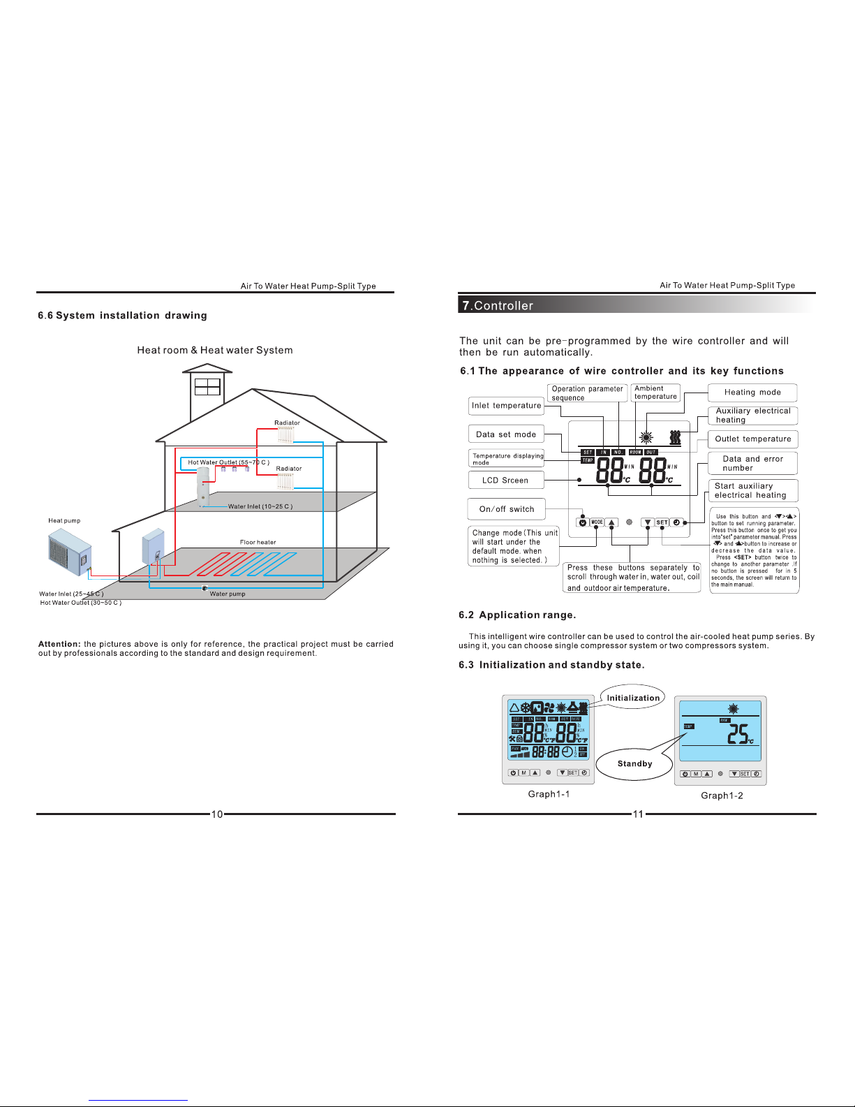
3.System Drawing
A
Fix the two pieces of fixing bars
to the place where the indoor unit
will be mounted.
The vertical distance between the
two fixing bars are 402mm.
After the fixing bars are well installed,
steadily hang the indoor unit on the fixing
bars, then button up the four hooks ensuring
that indoor unit is fixed firmly and stably. 2 4 0 m m
4 0 2 m m

9
B
C
2. After verifying the connection is right, the power can be on.
Terminal on main power
o
o


Time clock setting
1.Press button “SET “for 3 seconds to enter into the time clock setting
interface. Then you will see the flashing “hour” and “min”;
2.When the “hour” and “min” are both flashing, press button “SET”,
there will be only the “hour” flashing. Then press “▲”and “▼”to set
the required hour;
3.After the hour setting, press button “SET”, there will be only “min”
flashing, then press “▲”and “▼”to set the required minute;
4.After the minute setting, press button “SET”for confirming and saving
the time setting, then system will come back to main interface.
Timer setting
“ ” button
1.In the main interface, press “ ” button for three seconds to enter
timing setting interface;
2.In timing setting interface, “ON”flasing shows timing switch on,
“OFF” flashing shows timing switch off. Press “ ” button to change
the setting between “hour” and “min”, using “▲”and “▼”to set the
required time;
3.In timing setting interface, press “ ” button to save the current
setting time, then exit the timing setting interface and back to main
interface;
4.In timing setting interface, press “SET”button to cancel all of the
setting time, then exit the timing setting interface and back to main
interface.
19

Failure Possible causes Solutions
1. Power source failure 1. turn off the switch and
check the power source
2. Loosened wiring 2. find the caused and repair
3. The power fuse has broke 3. change a new fuse
1. Water leakage of the water
system
1. check the water supply
device and inject water
2. There is air in the system 2. Discharge the air
3. the valves are not open
entirely 3. open the valves completely
4. Filter blockage 4. Wash the filter
1. refrigerant shortage 1. check leakage and supply
refrigerant
2. bad water thermal insulation 2. Improve the insulation
3. bad heat elimination of air
heat exchanger
3. wash the heat exchanger
and improve condensing
4. Water flow shortage 4. Wash the filter
1. Excessive refrigerant 1. discharge unwanted
refrigerant
2. Bad heat elimination of air
heat exchanger
2. Wash the heat exchanger
and improve condensing
1. refrigerant shortage 1. check leakage and supply
refrigerant
2. filter or capillary blockage 2. change new filter or capillary
3. water flow shortage 3. wash the filter or discharge
the air in the system
4. Capillary in the expansion
valve cracks 4. change the expansion valve
1. power source failure 1. examine the power source
and eliminate the failure
2. compressor contactor
failure 2. change the contactor
3. loosened wiring 3. check and repair it
4. Compressor over loading
protection
4. compressor over loading
protection
5. wrong setting for inlet water
temperature 5. Reset it
6. Water flow shortage 6. Wash the filter or discharge
the air in the system
No running of the unit
The pump is running
without water
recycling or with high
noise
Low refrigerant capacity
while
compressors are running
Over-high outlet
pressure of compressors
Over-low inlet pressure
of compressors
No running of
compressors
9.1
20 21
Failure Possible causes Solutions
1. Liquid refrigerant into the
compressor
1. Check the cause and
eliminate it
2. compressor crash 2. change the compressor
1.Relay failure 1. change the relay
2. fan motor destroyed 2. change the fan motor
1. completely leakage of
refrigerant
1. examine leakage and supply
refrigerant
2. Tube-in-tube heat exchanger
ruined
2. change the tube-in-tube heat
exchanger
3. Compressors fault 3. Change compressors
1. water flow shortage 1. Wash the filter or discharge
the air in the system
2. Low setting value on
temperature 2. Reset the temperature
1. water flow shortage 1. wash the filter or discharge
the air in the system
2. water switch damage 2. Change the switch
The compressors are
running, but the unit
is not cooling/heating
Low water temperature
protection
Low water flow
protection
High noise of
compressor
No running of fan
motors
9.2System Status
Code Description Range Remark
IN Water inlet temp. -9℃~99℃Actual value
OUT Water Outlet tem p. -9℃~99℃Actual value
P1 Coil temp. -9℃~99℃Actual value
P2 Suction temp. -9℃~99℃Actual value
P3 Am bient tem p. -9℃~99℃Actual value
P4 Cooling coil temp. 0℃~F9℃(249℃) Actual value
P5 Step of electronic expansion
valve 0P~500P Actual value

22
Parameter
Function Range Value
00 Water inlet temperature during
cooling mode 8-28℃12℃
01 Water inlet temperature during
heating mode 15-60℃50℃
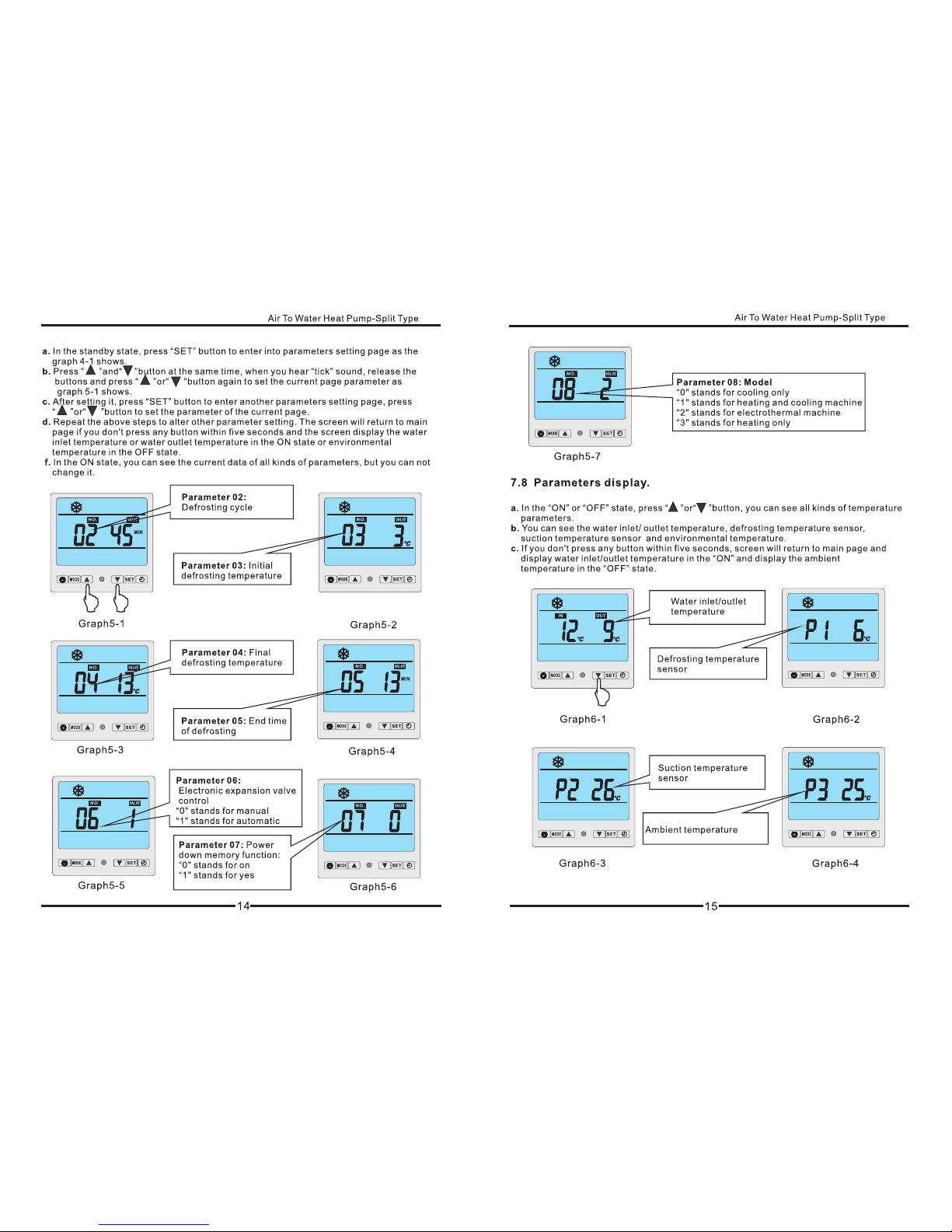
02 Defrosting cycle 30-90Min 45Min
03 Initial defrosting temperature 0--30℃-9℃
04 Final defrosting temperature 2-30℃13℃
05 End time of defrosting 1-12Min 10Min
06 Electronic expansion valve control 0-1 1
07 Power down memory function 0-1 1
08 Model 0-3 1
9 Work Pattern of water pump 0(Ordinary)
/1(Special) 0
a Automatic water inlet temp.setting 8℃-60℃40℃
b Target superheat temp. -F(-15℃)~
F(15℃)5℃
cManual adjustment of electronic
expansion valve 15~47 35
9.3 Parameter
23
Protection/Alarm Error Code Operation/Error indicator light
Standby state off
Booting normally on
Water inlet temp. sensor
fault PP 01 ☆●(Flashes on once and off once)
Water outlet temp. sensor
fault PP 02 ☆☆●( Flashes on twice and off once)
Coil temp. sensor fault PP 03 ☆☆☆●( Flashes on 3 times and off once)
Suction temp. sensor fault PP 04 ☆☆☆☆●( Flashes on 4 times and off
once)
Ambient temp. sensor
fault PP 05 ☆☆☆☆☆●( Flashes on 5 times and off
once)
Water outlet and inlet
temp. differences
overlarge protection
PP 06 on
Sub-cooling protection
under cooling mode PP 07 on
The First-degree
antifreezing protection in
winter
PP 07 off
The Second degree
antifreezing protection in
winter
PP 07 off
Cooling coil tem p. sensor
fault PP 08 ☆☆☆☆☆☆☆☆☆●( Flashes on 9 times
and off once )
High pressure protection EE 01 ☆☆☆☆☆☆●( Flashes on 6 times and off
once )
Low pressure protection EE 02 ☆☆☆☆☆☆☆●( Flashes on 7 times and
off once)
Water flow fault EE 03 ☆☆☆☆☆☆☆☆●( Flashes on 8 times
and off once)
Phase sequence
protection EE 04 ☆☆☆☆☆☆☆☆☆☆☆☆●(Flashes on 12
times and off once)
Water outlet and inlet
temp. overlarge fault EE 05 ☆☆☆☆☆☆☆☆☆☆●(Flashes on 10
times and off once)
Discharge temp.
overlarge protection EE 06 ☆☆☆☆☆☆☆☆☆☆☆●(Flashes on 11
times and off once)
Defrosting ☆☆☆☆☆☆☆☆……(Always flashing)
Communication fault EE 08 (The fault is only effective on rem ote
controllers)
MODEL:CKST-4SH
24
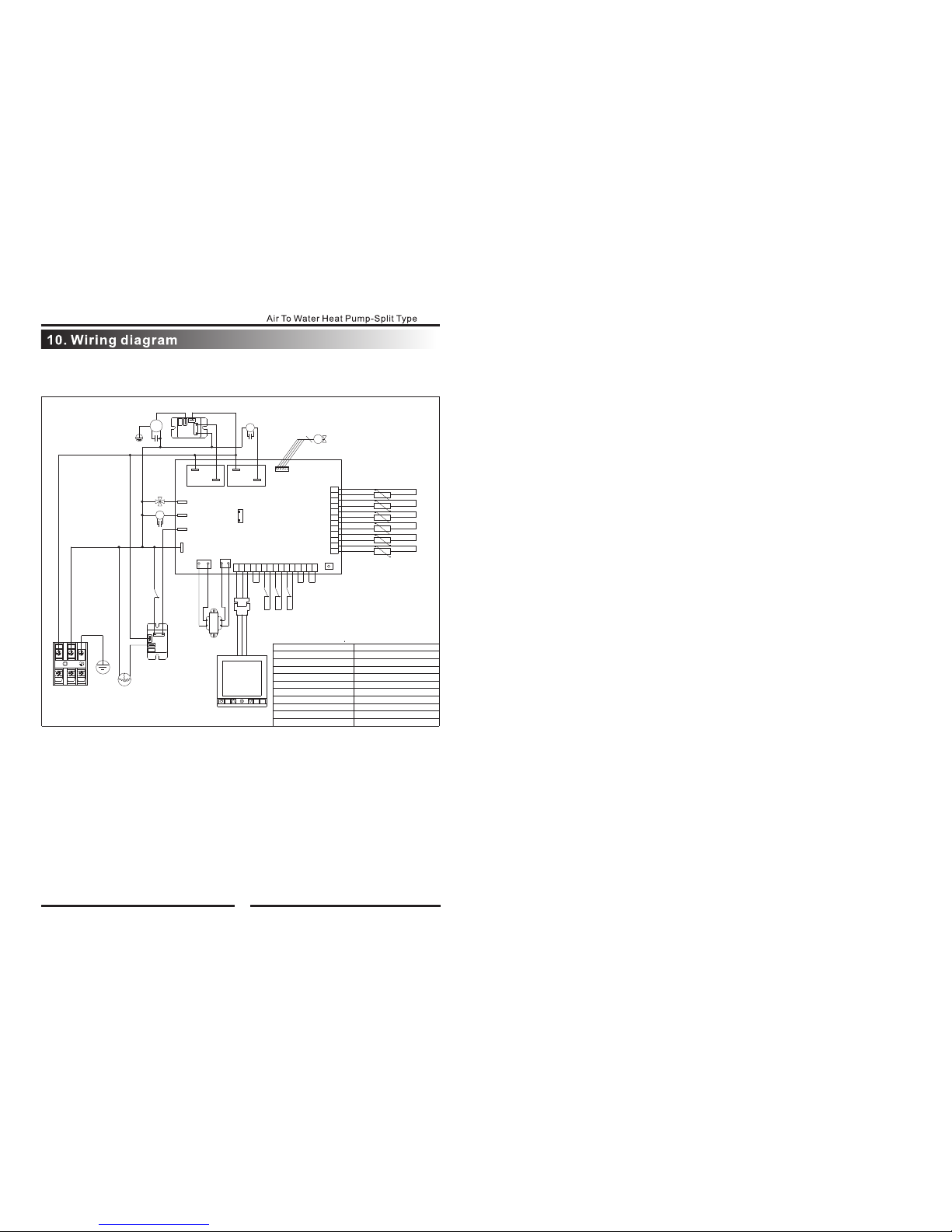
F3 F1
R3
V1
A2
AUXSET
M
V2
E
R5
L N
T1
R6
R4
R2
R1
M1
R
C
S
M2 A1
F2
(AC220V)
E1
CN3 CN4
CN2
CN1
AC-N
OUT5
OUT4
OUT3
OUT2
SW1
OUT1
CN19
CN7
K1
COM
NO
M3
K2
COM
NO
E2
F4
temperature control switch
F4
K2 electric heater relay
E1 transformer
M3 water pump
coil sensor
F3 water flow switch
F2 low pressure switch
cooling coil sensor
electrical expansion valve
V2
K1 Comp relay
fan
M2
R6
4-way valve
E2 electric heater
ambient sensor
R5
F1 high pressure switch
water outlet sensor
R4
water inlet sensor
suction gas sensor
R1
M1 Compressor
A2 wire controller
A1 main control board
T1 power supply
V1
R2
R3
Table of contents
Other Chigo Heat Pump manuals


Popular Heat Pump manuals by other brands


CLIMAVENETA
CLIMAVENETA AW HT 0031 Installation - user - maintenance manual

Carrier
Carrier 38BQ Installation, Start-Up and Service Instructions

LG
LG ARNU12GSER1 owner's manual

Calorex
Calorex C-PAC+ CPT6 ALY Owners & installation manual

Daikin
Daikin Altherma 3 R W Installer's reference guide

Daikin
Daikin Altherma 3 H F Installer's reference guide