Chigo CKF-34CV User manual

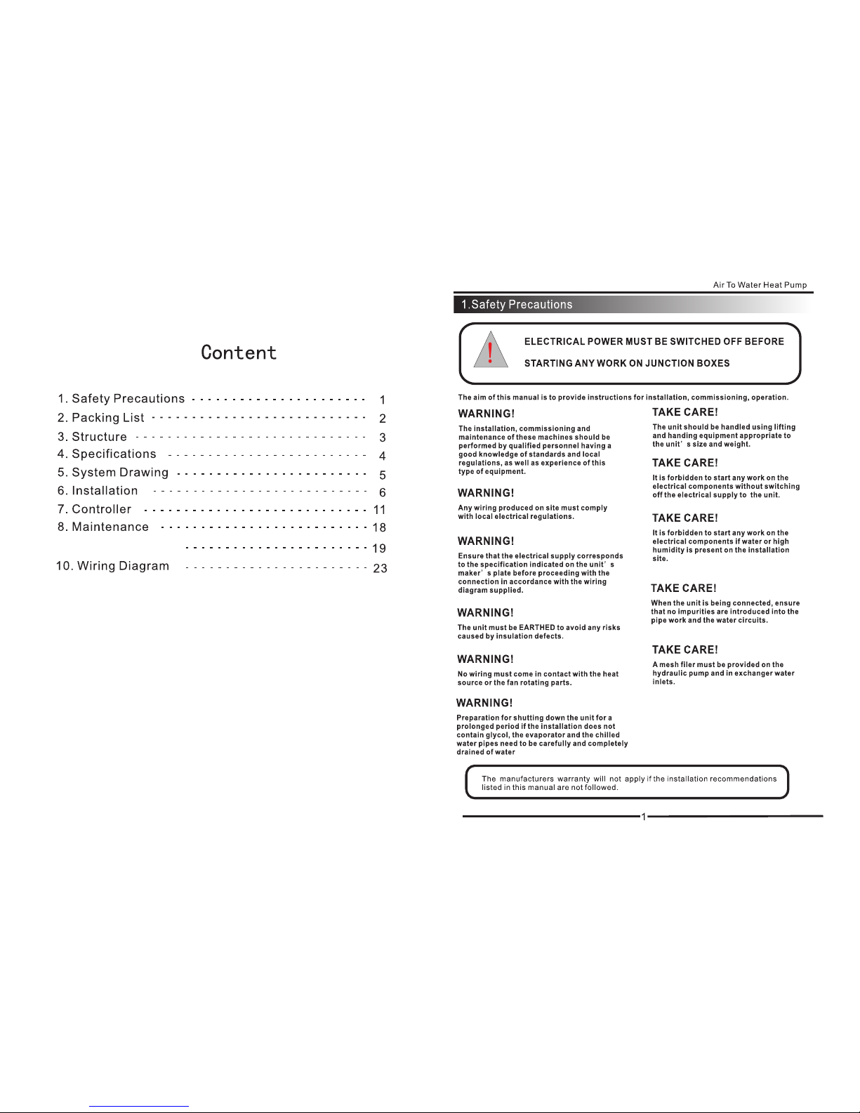
Air To Water Heat Pump
MODEL:CKF-34CV
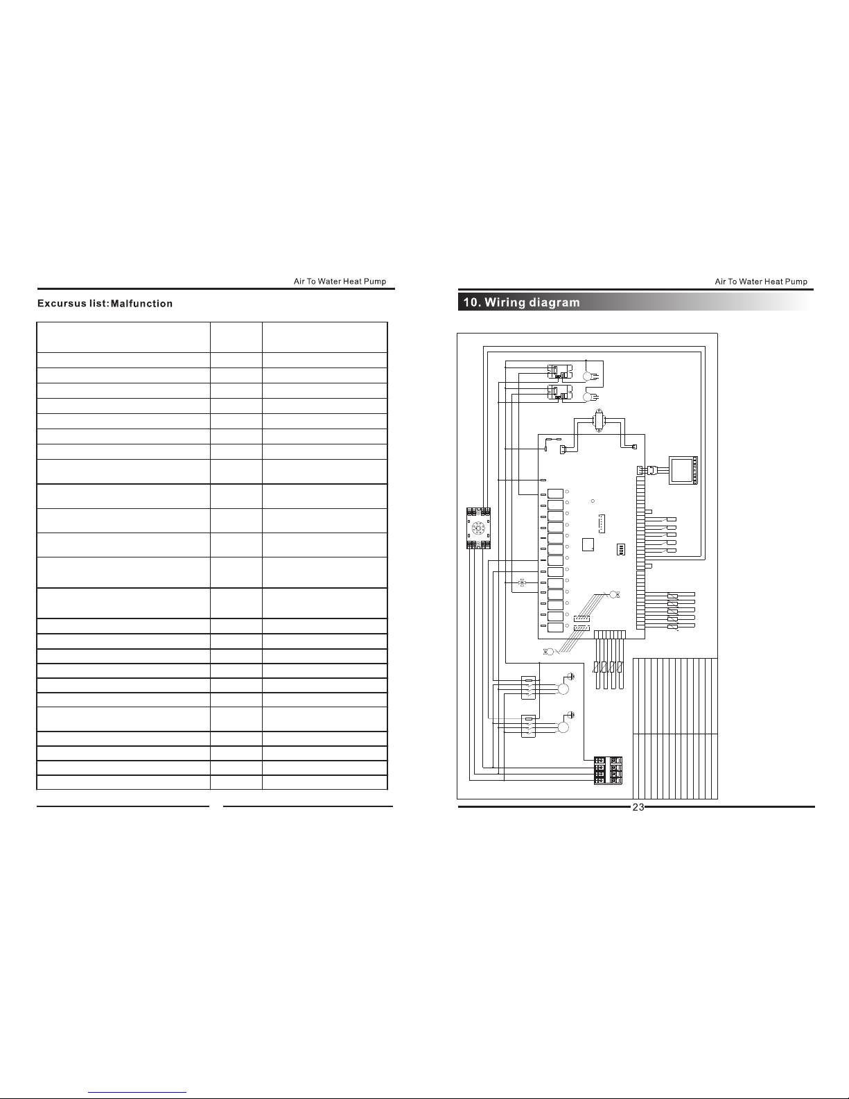
9. Trouble shooting
2
+
X4
Expansion screws:
3
● Outer Structure
12
67
3
4
5
8
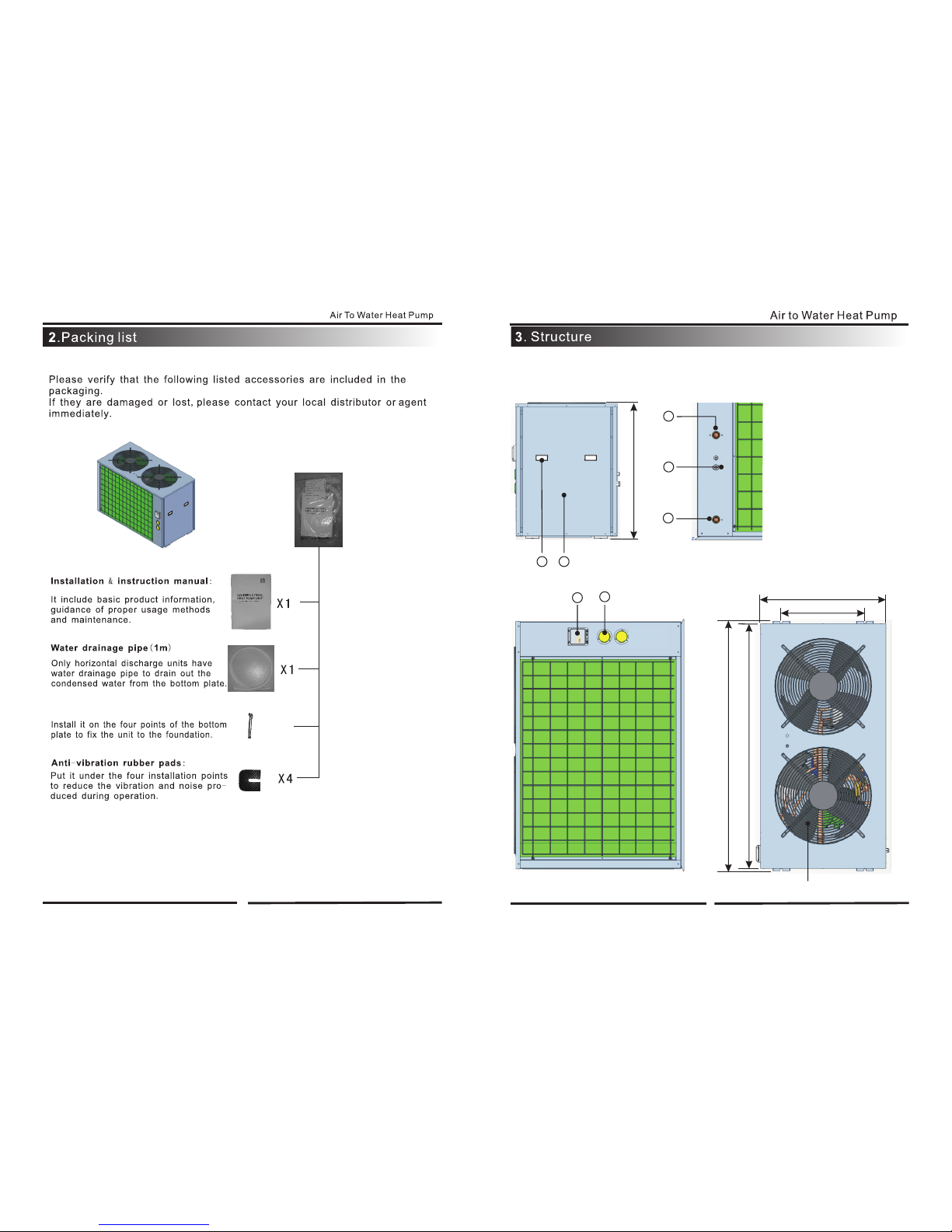
1.Handle
2.Maintenance Door
3.Water Outlet
4.
Water Inlet
6.Wire Controller And
Waterproof Box
7.Pressure Gauge
8.Fan and Motor
Power Supply
5.
990mm
1440mm
1470mm
494mm
735mm

4
Model CKF-34CV
Voltage/Phase/Frequency 380-400V/3PH/50HZ
Amps Per Phase 19.5Amps
Min. Circuit Size 25.4Amps
Heating Capacity 33.5KW
Heating Power Input 9.6KW
Sound Level 60dB(A)@3m
Type Scroll
Number Per Unit 2
FLA (Full Load Amp) 11*2Amps
Voltage/Phase 380~400V/3PH
Type External Rotor
Number Per Unit 2
Power Input 0.25*2KW
Voltage/Phase 220~240V/1PH
Fan Speed 850Rpm
Type Plate Type Heat Exchanger
Water Flow Rate (m3/h) 5.8
Max. Outlet Water Temp 55℃
Water Connections 1.5 Inch
Refrigerant R410a
Defrost Automatic Hot Gas Injection
Shipping Weight 296 kg
Dimensions L x W x H (cm) 147 x 73.5 x 99
※Heating: Outdoor Air Temp:15℃ DB ,11℃WB, Water Temp: 35℃
GENERAL INFORMATION
HEAT EXCHANGER (Water Side)
AIR TO WATER HEAT PUMP SPECIFICATIONS
Fan
Compressor
PERFORMANCE
ELECTRICAL INPUT
TECHNICAL DATA
7

9
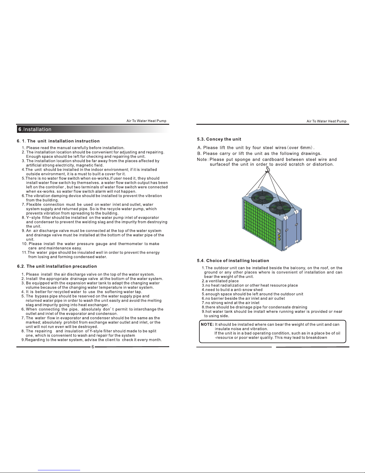
Soft connection
Automatic
drain valve


19
Failure Possible causes Solutions
1. Power source failure 1. turn off the switch and
check the power source
2. Loosened wiring 2. find the caused and repair
3. The power fuse has broke 3. change a new fuse
1. Water leakage of the water
system
1. check the water supply
device and inject water
2. There is air in the system 2. Discharge the air
3. the valves are not open
entirely 3. open the valves completely
4. Filter blockage 4. Wash the filter
1. refrigerant shortage 1. check leakage and supply
refrigerant
2. bad water thermal insulation 2. Improve the insulation
3. bad heat elimination of air
heat exchanger
3. wash the heat exchanger
and improve condensing
4. Water flow shortage 4. Wash the filter
1. Excessive refrigerant 1. discharge unwanted
refrigerant
2. Bad heat elimination of air
heat exchanger
2. Wash the heat exchanger
and improve condensing
1. refrigerant shortage 1. check leakage and supply
refrigerant
2. filter or capillary blockage 2. change new filter or capillary
3. water flow shortage 3. wash the filter or discharge
the air in the system
4. Capillary in the expansion
valve cracks 4. change the expansion valve
1. power source failure 1. examine the power source
and eliminate the failure
2. compressor contactor
failure 2. change the contactor
3. loosened wiring 3. check and repair it
4. Compressor over loading
protection
4. compressor over loading
protection
5. wrong setting for inlet water
temperature 5. Reset it
6. Water flow shortage 6. Wash the filter or discharge
the air in the system
No running of the unit
The pump is running
without water
recycling or with high
noise
Low refrigerant capacity
while
compressors are running
Over-high outlet
pressure of compressors
Over-low inlet pressure
of compressors
No running of
compressors
9.1

20
Failure Possible causes Solutions
1. Liquid refrigerant into the
compressor
1. Check the cause and
eliminate it
2. compressor crash 2. change the compressor
1.Relay failure 1. change the relay
2. fan motor destroyed 2. change the fan motor
1. completely leakage of
refrigerant
1. examine leakage and supply
refrigerant
2. Tube-in-tube heat exchanger
ruined
2. change the tube-in-tube heat
exchanger
3. Compressors fault 3. Change compressors
1. water flow shortage 1. Wash the filter or discharge
the air in the system
2. Low setting value on
temperature 2. Reset the temperature
1. water flow shortage 1. wash the filter or discharge
the air in the system
2. water switch damage 2. Change the switch
The compressors are
running, but the unit
is not cooling/heating
Low water temperature
protection
Low water flow
protection
High noise of
compressor
No running of fan
motors
9.2System Status
Code Description Range Remark
IN Water inlet tem p. -9℃~99℃Actual value
OUT Water Outlet tem p. -9℃~99℃Actual value
P1 System1 coil temp. -9℃~99℃Actual value
P2 System2 coil temp. -9℃~99℃Actual value
P3 Ambient tem p. -9℃~99℃Actual value
P4 System1 cooling coil tem p. -9℃~99℃Actual value
P5 System1 step of electronic
expansion valve 150P~470P Actual value
P6 System2 cooling coil tem p. -9℃~99℃Actual value
P7 Sys tem1 suction temp. -9℃~99℃Actual value
P8 Sys tem2 suction temp. -9℃~99℃Actual value
P9 System2 step of electronic
expansion valve 150P~470P Actual value
21
Parameter
Function Range Value
00 Water inlet temperature during
cooling mode 8-28℃12℃
01 Water inlet temperature during
heating mode 15-60℃50℃
02 Defrosting cycle 30-90Min 45Min
03 Initial defrosting temperature 0--30℃-9℃
04 Final defrosting temperature 2-30℃13℃
05 End time of defrosting 1-12Min 10Min
06 Electronic expansion valve control 0-1 1
07 Power down memory function 0-1 1
08 Model 0-3 1
9 Work Pattern of water pump 0(Ordinary)
/1(Special) 0
a Automatic water inlet temp.setting 8℃-60℃40℃
b System1 target superheat temp. -F(-15℃)~
F(15℃)5℃
cManual adjustment of electronic
expansion valve 15~47 35
b System2 target superheat temp. -F(-15℃)~
F(15℃)5℃
9.3 Parameter
Air To Water Heat Pump
22
Protection/Alarm Error Code Operation/Error indicator
light
Standby state off
Booting normally on
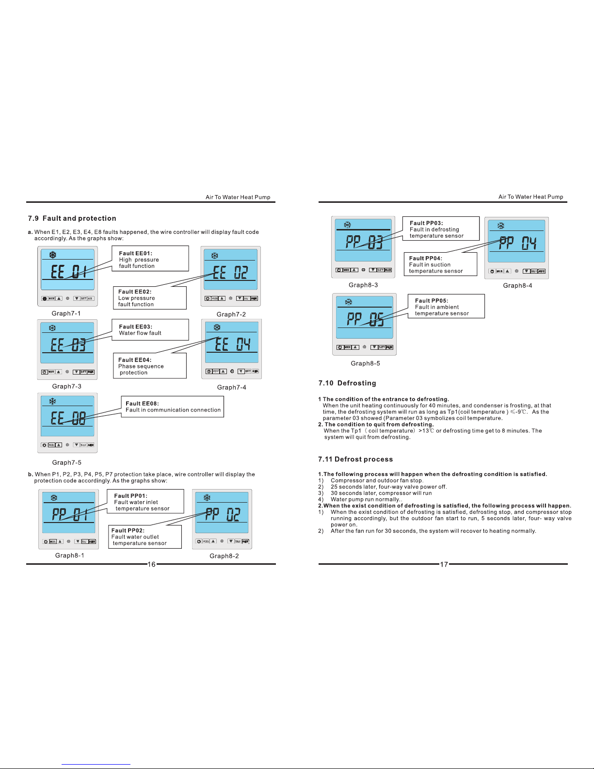
Water inlet temp. sensor fault PP 01
Water outlet temp. sensor fault PP 02
System1 coil temp. sensor fault PP 03
System1 suction temp. sensor fault PP 04
Ambient temp. sensor fault PP 05
Water outlet and inlet temp. differences
overlarge protection PP 06
Sub-cooling protection under cooling
mode PP 07
The First-degree antifreezing protection
in winter PP 07
The Second degree antifreezing
protection in winter PP 07
System1 cooling coil temp. sensor fault PP 08
System2 cooling coil temp. sensor fault PP 09
System2 coil temp. sensor fault PP 10
System2 suction temp. sensor fault PP 11
System1 high pressure protection EE 01
System1 low pressure protection EE 02
Water flow fault EE 03
Phase sequence protection EE 04
Water outlet and inlet temp. overlarge
fault EE 05
System2 high pressure protection EE 07
System2 low pressure protection EE 09
Defrosting
Communication fault EE 08
MODEL:CKF-34CV
OUT13 OUT12 OUT11 OUT10 OUT9 OUT8 OUT7 OUT6 OUT5 OUT4 OUT3 OUT2 OUT1
01 02 03 04 05 06 07 08 09 10 11 12 13 14 15 16 17 18 19 20 21 22 23 24
01 02 03 04 05 06 0708 09 10 11 12 1314 15
01 02 03 04 05 06 07 08
ON DIP
1 2 3 4
I;C
LED1
LED2
LED3
LED4
LED5
LED6
LED7
LED8
LED9
LED10
LED11
LED12
LED13
N3
N2
AC-N
AC-L
PP05
PP01
PP02
PP03
PP10 PP04 PP11 PP08 PP09 EE03
EE04 EE09
EE07EE02EE01
water inlet sensor
water outlet sensor
F5
low pressure switch1
F4
cooling coil sensor1
electrical expansion valve1
V2
V1
KM1/KM2 Comp AC contactor
fan
M3
R6
4-way valve
E1 transformer
ambient sensor
R5
F3
high pressure switch1 coil sensor1
R4
suction gas sensor1
R1
M1/M2 compressor
F2
F1 water flow switch
T1 power supply
V1
R2
R3
E1
F2F1
MSET AUX
A2
F3 F4 F5
R5 R6 R7 R8 R9
R1
R2
R3
R4
E
V3
E
V2
A1
main control board
wire controller
A2
A1
low pressure switch2
high pressure switch2
electrical expansion valve2
V3
R9
R8
cooling coil sensor2
R7
coil sensor2
suction gas sensor2
M2
(AC380V)
R S T N
T1
KM1
M1
KM2
phase sequence protection board
A3
K2K1
M3
COM
NO NO
COM
A3
5
6
7
8
4
321
relay
K1/K2
M4
water pump
M4
Other Chigo Heat Pump manuals


