Chilicon Power CP-720 User manual

Residential Design and Installation Guide
April 2020

Chilicon Power Residential Design and Installation Guide 2
Contact Information:
US Customer Service
support@chiliconpower.com
Tel: (310) 800-1396
Chilicon Power Inc
15415 Sunset Blvd Suite 102
Pacific Palisades, CA 90272
Tel: (310) 800-1396
www.chiliconpower.com
Safety Directives and Code Compliance
Chilicon Power directs all customers to comply with all national and local safety and code requirements when
installing equipment. To maintain product warranty, these directions must be followed when installing, operating
and servicing the unit. If ignored, injury or death may happen, as well as damage to the unit.
Read these Instructions before working on the unit. If you are unable to understand the Dangers, Warnings,
Cautions or Instructions, contact the manufacturer or authorized service agent before installing, operating and
servicing the unit. The inverters described in this document meets the requirements stipulated in:
•NEC 2017 Section 690.11 &12 Rapid Shutdown of PV Systems on Buildings
•NEC 2017 Section 705.12 Point of Connection
•IEEE 1547-2018 IEEE Standard for Interconnection and Interoperability of Distributed Energy Resources with
Associated Electric Power Systems Interfaces
•UL 1741 SA Standard for Inverters, Converters, Controllers and Interconnection System Equipment for Use
with Distributed Energy Resources
•IEEE 2030.5-2018 IEEE Standard for Smart Energy Profile Application Protocol
Other Information
All information, instructions, specifications, and illustrations in this manual are those in effect at the time of
printing. Chilicon Power reserves the right to change specifications or design at any time without notice.
For the most current information, please visit our website at www.chiliconpower.com
All trademarks are recognized as the property of their respective owners.
Copyright © 2020 Chilicon Power. All rights reserved.

Chilicon Power Residential Design and Installation Guide 3
Contents
Notes ........................................................................................................................................................ 4
1.1 Focus .................................................................................................................................................... 4
1.2 Symbols used........................................................................................................................................ 4
1.3 Safety Instructions................................................................................................................................ 4
Introduction................................................................................................................................................ 5
2.1 The Chilicon Advantage: More Flexibility, More Productivity ............................................................. 5
2.2 Products ............................................................................................................................................... 6
2.3 System Design ...................................................................................................................................... 6
2.4 Compatibility ........................................................................................................................................ 7
2.5 Packaging.............................................................................................................................................. 7
2.6 Microinverter Marking ......................................................................................................................... 7
Installation..................................................................................................................................................7
3.1 Required Parts & Tools......................................................................................................................... 8
3.2 Lightning Surge Suppression ................................................................................................................ 8
Installation Procedure ................................................................................................................................ 9
4.1 Installation............................................................................................................................................ 9
Step 1: Measure Grid AC Voltage at the Service Panel..............................................................................9
Step 2: Position the Microinverters and Loosely Secure on the Rails......................................................10
Step 3: Complete the Installation Map ....................................................................................................10
Step 4: Layout the Trunk Cable and Connect the Sections ......................................................................11
Step 5: Adjust the Microinverters and Secure to the Racking .................................................................12
Step 6: Connect the Microinverters to the PV modules and Trunk Cable ...............................................11
Step 7: Install the AC branch Circuit Junction Boxes................................................................................12
Step 8: Connect the System to the Main Service Panel...........................................................................13
Step 9: Install the Gateway and Commission the System........................................................................ 12
Step10: Finish Entering Additional Information On-line.......................................................................... 13
4.2 Z-Wave Energy Monitoring Installation ............................................................................................. 14
Appendices...............................................................................................................................................15
Reference Single Line Drawings................................................................................................................16
Connections Insert Guide......................................................................................................................... 18
Commissioning Quick Guide .................................................................................................................... 20
Technical Bulletin: Branch Circuit Sizing...................................................................................................21
Technical Bulletin: Power Limiting of Microinverters...............................................................................22
Technical Bulletin: Voltage Rise Calculations............................................................................................24
Technical Bulletin: Chilicon Microinverters on a 40 A Backfeed...............................................................28
Technical Bulletin: Surge Protection for Microinverter Systems ..............................................................29
Cabling Guide ...........................................................................................................................................30

Chilicon Power Residential Design and Installation Guide 4
Notes
1.1 Focus
This installation manual describes the design, installation, and commissioning of residential systems using the
Chilicon Power CP-720and CP-250E line of microinverters.
1.2 Symbols used
The following symbols are used in this manual and on Chilicon microinverters:
WARNING!
This indicates a safety hazard that could cause personal injury or equipment
malfunction. Follow these instructions carefully to avoid or reduce the risk.
HIGH VOLTAGE
This indicates a specific safety hazard relating to areas with 240V AC present
This indicates that the product conforms to all applicable UL testing standards as
confirmed by Intertek Corporation, an independent testing agency.
1.3 Safety Instructions
1. Follow local installation codes. Make sure to adhere to all applicable national and local electrical codes
during installation. Only qualified personnel should install or replace Chilicon Power microinverters.
2. No DIY repairs. Users must never attempt to repair or modify the Chilicon Power microinverters themselves. If
the microinverter fails to operate, contact Chilicon Power customer service for repair or replacement. Tampering
with or opening the hardware will void the warranty.
3. Read all instructions. Read all of the instructions and cautionary notes in this manual and referenced
supporting documents before installing the hardware.
4. Install safely. Do not connect the system to the AC power grid until the conclusion of the assembly process
and disconnect the AC power grid connection first before disconnecting the PV module from the Chilicon
microinverter or the microinverters from the AC trunk cable.
5. Microinverters can get hot. The case of the Chilicon microinverter acts as a heat sink. Under normal
operating conditions, the case temperature is approximately 36 °F (20°C) above ambient. However, under
extreme conditions the case temperature can reach 149°F (65°C) or more. Chilicon therefore recommends
wearing gloves when working with microinverters.

Chilicon Power Residential Design and Installation Guide 5
Introduction
Welcome to the Chilicon Power family of microinverter system installers. Chilicon Power offers the most
advanced microinverter system commercially available. This system is versatile, highly reliable, high performance,
and easy to install by following the instructions contained in this manual. Three elements constitute the
Chilicon Power system:
• Chilicon Power single or duo microinverter
• Communications gateway
• Web-based monitoring software
2.1 The Chilicon Advantage: More Flexibility, More Productivity
Microinverters offer enhanced reliability, production, and flexibility in PV system design and operation.
Conventional solar systems string numerous solar panels together and connect them all to a single inverter. This
approach requires series connecting the PV modules into “strings” which causes a loss in production when some
of the modules are shaded by clouds, trees, or debris. Furthermore, the string inverter represents a single point
of failure which if fails will result in a total loss of production from the PV system.
String Inverter Microinverter
Production Limited by weakest module Maximized for system
System Risks The whole system Isolated to the module
System Design Requires string calculations Simple branch circuits
DC High Voltage Yes No
DC Arc Fire Risk Yes No
Rapid Shutdown Compliant Requires additional hardware Fully compliant
Per module visibility No Yes
Installation Additional location required Hidden under solar module
Warranty (yrs) 10-12 yrs 25 yrs
The Chilicon Power system consists of either single (CP-250E) or duo (CP-720) high performance microinverters
connected together using standardized lengths of Chilicon Power MTC AC trunk cable into up to 30A breakers.
The CP100 gateway connects via a standard 120V electrical outlet to both receive microinverter data via a robust
PLC link and serve as a master control panel, allowing full access to firmware modification of the microinverters.
This significantly simplifies processes such as power limiting for support of larger branch circuits and AC coupling
for system which include generators or batteries. Finally, all information is uploaded to our cloud based
monitoring system for remote viewing and ease of O&M support.

Chilicon Power Residential Design and Installation Guide 6
2.2 Products
Chilicon offers the following products to support photovoltaic projects:
Microinverters
CP-250E Single input microinverter for 60 or 72 cell modules
CP-720 Dual input microinverter for 60, 72, 96 or 128 cell modules
Trunk Cabling
CP-MTC-1.025 1.025m cable - male connector one end and dual female connector on the other end
CP-MTC-1.7 1.7m cable - male connector one end and dual female connector on the other end
CP-MTC-2.15 2.15m cable - male connector one end and dual female connector on the other end
CP-MTC-JBOX 1.7m cable - bare wire on one end and dual female connector on the other end
CP-WTPRF-CAP Cap to seal unused female connectors
Communication Devices
CP-GWY-100 Communication gateway
CP-HEM Aeon Labs Gen 5 Z-wave energy meter (ZW095)
CP-ZW-Rep Aeon Labs Gen5 Z-wave repeater (ZW117)
Tooling
CP-AC-Tool Disconnect tool for AC trunk cable connections
CP-DC-Tool Disconnect tool for DC MC4 connectors
2.3 System Design
Designing a system using Chilicon Power microinverters is straight forward provided the following areas are
addressed prior to deployment:
1) Branch Circuit Sizing: The number of microinverters deployed on a branch circuit must not exceed the
maximum allowable current of 24 A supported by the Chilicon Power #10 AWG MTC trunk cabling. For the
CP-250E, each microinverter can produce 1.2A (@240V) at full power for a maximum of 20 inverters per branch
circuit, while the CP-720 can produce 3.0 A (@240V) at full power for a maximum of 8 duos (16 PV modules).
However, Chilicon Power provides the ability to self-limit microinverter power to support larger branch circuits for
lower wattage modules. Refer to Chilicon Power’s “Technical Bulletin: Branch Circuit Sizing” and “Technical
Bulletin: Power Limiting of Microinverters” for more details on this subject. These documents as well as reference
single line drawings for typical branch circuits can be found in the appendix of this document.
2) Voltage Rise:The linking of microinverters along a branch cable results in an increasing voltage at each node
in addition to the voltage rise associated with the cabling connecting the branch circuits to the main service panel.
Suitable wire sizing and connection topology should be exercised such that the voltage at the last micro does not
exceed 264V. Refer to Chilicon Power’s “Technical Bulletin: Voltage Rise Calculations” found in the appendix for
more details on this subject. Furthermore, should the situation require, it is possible to extend the 264V upper
shutdown limit. Please contact a Chilicon representative for more details on this procedure.

Chilicon Power Residential Design and Installation Guide 7
3) Module Layout and Orientation: The three standard length MTC cable sections make for easy deployment
in either portrait or landscape mode for either 60, 72 or 96 cell modules for the CP-250E, placing one
microinverter per module. However, the layout and cabling using the CP-720 dual microinverter requires
additional planning. Use of modules with DC leads shorter than 1.2m long can significantly complicate the
layout and may require the use of additional DC jumper cables, which Chilicon Power strongly discourages. The
most efficient layout is usually even rows of PV modules facing each other such that both sets of MC4 DC cables
can easily connect to one microinverter. This and other common configurations are described in the Chilicon
Power “Cable Guide” located in the appendix. Chilicon Power highly recommends reviewing it to determine the
optimal layout and cable lengths needed during project design.
2.4 Compatibility
The CP250E model is compatible with both 60-cell and 72-cell PV modules.
The CP-720 model is compatible with 60, 72, 96, and 128 cell modules.
All microinverters come with TI-Lane MC4 DC connectors. The connectors are a recognized component, tested
by UL (certification file number E347414). Other connector options may be available as specials.
2.5 Packaging
Chilicon Power ships product per the following table of box sizes and weights:
Product Weight per (lbs) Quantity per Box Box Dimensions Box Weight (lbs)
CP-250E 3.4 5 15" x 13" x 10.5" 18
CP-720 4 5 15" x 13" x 10.5" 21
CP-MTC-1.025 1 50 16" x 16" x 16" 50
CP-MTC-1.7 1.5 25 16" x 16" x 16" 40
CP-MTC-JBOX 1.5 25 16" x 16" x 16" 40
CP-MTC-2.15 1.9 20 16" x 16" x 16" 40
Broken quantities will be shipped in boxes of alternate dimensions and weights.
2.6 Microinverter Marking
The microinverter label contains the company name and logo, operating parameters, safety warnings, and the
unit serial number. The serial number identifies the batch or production date of the device. Chilicon Power
recommends making an installation map showing the location of all inverters on the site. A second, peel-off serial
number is included to facilitate marking the project site map.

Chilicon Power Residential Design and Installation Guide 8
Installation
3.1 Required Parts & Tools
The Chilicon microinverter system is designed to be installed using minimal effort and tooling. In addition to the
parts detailed in Section 2.2, the following parts and tools are required:
Other parts:
• MLPE rail or frame attach clamp
• AC junction boxes (need with ¾” or 1” threaded holes/knock-outs)
• A subpanel may be required for systems with multiple branch circuits
• Cordgrip with locknut or strain relief fitting (one per AC junction box)
(e.g. Heyco M3234GA+2251for ¾” or M8437+2252 for 1”)
• Cable clips
(e.g. Heyco S6441,S6442 or Nine Fasteners Inc. DCX-2452A)
• MC4 Y connectors or branch connector- One pair per micro for 96 or 128 Cell modules
(e.g. JHBOX Connectors Y Branch Parallel Adapter Cable or Renogy MC4 Y Branch Connectors)
Tools:
• Multimeter
• Torque wrench
• Sockets
• Adjustable wrench
• Flat head and Phillips head screwdrivers
• Allen wrench torque driver
• Impact drill (optional)
• Handheld mirror with extension rod (to view indicator LED on the microinverters)
3.5 Lightning & Surge Suppression
PV systems are typically installed on rooftops or other open areas - places where lightning can strike. Lightning
causes massive voltage spikes in solar arrays, which may damage equipment. While Chilicon Power

Chilicon Power Residential Design and Installation Guide 9
microinverters have built-in surge protection, this may not always protect the devices from the energy spike
caused by lightning. Additional surge protection devices are strongly recommended. Please refer to Chilicon
Power’s “Technical Bulletin: Surge Protection for Microinverter Systems” located in the appendix for more details.
Installation Procedure
4.1 Installation
Please read entire procedure prior to installing.
Step 1: Measure the AC voltage at the main service panel
Step 2: Position the microinverters on the rails and loosely secure
Step 3: Complete the installation map
Step 4: Layout the trunk cable and connect the sections
Step 5: Reposition the microinverters and secure to the racking
Step 6: Connect the microinverters to the PV modules and trunk cable
Step 7: Install the AC branch circuit junction boxes.
Step 8: Connect the system to the main service panel
Step 9: Install the communication gateway and commission the system
Step 10: Finish entering additional site information on-line
Note: Chilicon Power recommends taking photos of the PV system during installation, including the panel label,
microinverter attachment to the racking, the junction box connection, and the system grounding.
DO NOT connect the Chilicon Power microinverters to the utility grid until you have checked that all
of the module and cable connections are correct and secure. Confirmation can be determined by
the correct microinverter blink codes.
Step 1: Measure Grid AC Voltage at the Main Service Panel
Using the multimeter, measure the AC line voltage at the main service panel to ensure it is within range for the
proper operation of each microinverter. The nominal voltage should be 240V AC. If the voltage is appreciably
above this, the system may experience microinverter shutdown at the end of the branch circuits due to node

Chilicon Power Residential Design and Installation Guide 10
voltages rising above those allowable by code. Should this situation arise, notify the local utility of the issue.
However, there is also the ability to adjust the upper shutdown voltage of the microinverters via the CP-GWY-100
gateway. Please contact a Chilicon Power representative for assistance.
Step 2: Position the Microinverter on the PV Racking and Loosely Secure
Attach the microinverter using the appropriate
MLPE mounting hardware for the PV racking
selected and loosely secure using either an
allen wrench or socket (depending on the
manufacturer). Keep loose enough such that
the microinverter can slide along the rail.
Note that the fina
l cable segment often
connects to two microinverters, so the last
microinverter in a branch circuit will need to be
within 2 feet from the end of the trunk cable.
Position the micro such that it will lie under the
PV module with the chassis facing downward
and
out of direct sunlight. Also, leave at least
0.6in (1.5cm) clearance between the roof and
the bottom of the microinverter; and at least
0.6 in (1.5cm) clearance between the back of
the PV module and the top of the microinverter.
For rail-less or ballast mount systems
it is
possible to attach the microinverter directly to
the PV module frame using a suitable mount,
such as Unirac 8114M Mount.
Step 3: Complete the Installation Map
While the CP-100 gateway can identify the various microinverters connected to the system, it cannot locate their
position in the layout. Therefore, it is important to capture this information during installation using the layout
map generated during the design. Once a microinverter is associated with a module (or set of modules), remove
the serial number label located on the microinverter and place it at the corresponding location on the map.
Also, at this time draw a line connecting the panels to be paired if installing the CP-720 dual microinverter. This
map will be used later when constructing the physical layout in the monitoring software. It is advisable to keep
the original copy of the installation map for your records.

Chilicon Power Residential Design and Installation Guide 11
Step 4: Layout the Trunk Cable and Connect the Sections
Do NOT exceed the maximum allowable number of microinverters in an AC branch circuit.
As Chilicon Power supplies three different lengths of trunk cable and the system may require different sections in
different locations, it is advisable to first layout the cable to ensure sufficient materials and placement for the
project. Use the CP-MTC-JBOX as the first cable for each branch circuit, making sure it’s associated J-Box can be
placed within 1.7 m (5.6’). The male end of the second cable segment (M1) will seat into one of the female
connectors on the J-Box cable (F1), with the first microinverters branch cable occupying the second slot (F2).
The connections should securely snap, locking them in place. In the event a connection needs to be undone,
use the CP-AC-Tool supplied by Chilicon Power. Continue connecting the rest of the cables in this manner until
the branch circuit is completed, repeating this process for any additional branch circuits in the system. If the
layout is such that no microinverter connects to one of the female connectors (the case in certain configurations),
use the CP-WTRPF-CAP to plug the unused female connector.Should span lengths be required not supported by
Chilicon Power standard MTC cable segments, two options are available to the installer. Either standard MTC
cable segments can be connected together (with caps on the open female connectors) or 4 wire TCER cable can
be used to connect the two sections terminating in J-Boxes at each end. The trunk cable should then be attached
to the racking system using suitable clips. In order to facilitate the Chilicon Power 5.7” diameter 10AWG trunk
cabling, it may be necessary to use a flat head screw driver to first pry open the cable clips.
F2
F1 M1
Alternative Center Tap Connection
For systems where a fully populated branch circuit may exceed voltage rise limits or where dictated by roof
topology, the design may call for a center-tap of the branch circuit. In this event, each subsection of the branch
will connect via a CP-MTC-JBOX cable to the same junction box and internal wiring.
Never leave unused AC cables ports open in the system. Terminate all unused ends
of any AC trunk cable with end caps.

Chilicon Power Residential Design and Installation Guide 12
Step 5: Reposition the Microinverters and Secure to the Racking
Once the position of the microinverters has been finalized, secure them by ether tightening with the allen wrench
or socket to the torque value specified by the manufacturer of the MLPE clamp. A value of 10.3 ft lbs (14 NM) is
typical for MLPE with allen bolts. Check with your MLPE clamp manufacturer for the appropriate torque values for
their hardware. These are typically around 12 ft lbs (16.3 NM).
Step 6: Connect the Microinverters to the PV Modules and Trunk Cable
For each microinverter, first connect the DC cables from the associated PV module(s). The modules will need to be
specifically oriented per the layout diagram such that their DC cables can readily reach each microinverter. Next, connect the
microinverter’s branch cable to the associated female connector on the AC MTC trunk cable. Both the DC and AC connections
will lock in place if properly connected. The most common issue during installation is failure to fully secure these
connections. Then, secure the module to the racking with the appropriate torque value. Each microinverter contains an
LED that will indicate connection status via a series of blink codes. Once connected to the PV module, the microinverter
will blink every 4 seconds. If difficult to see, use the mirror to get a better view of the light. This indicates that PV module is
in the process of initially charging the microinverter. Once the charging process has completed, the LED will continuously
blink. This indicates that the system is now ready for the application of AC current. Refer to the table below and the
“Chilicon Power Connection Insert” document in the appendix for a complete listing of the codes.
After DC Applied:
After AC Applied:
Step 7: Install the AC Branch Circuit Junction Boxes
1) Install an AC junction box at its proper location for each branch
circuit. The most common location is at the beginning or middle of
an AC branch. For the latter location, it will need to accommodate
two CP-MTC-JBOX cables. Note that the junction box will need
threaded holes with diameters of either ¾” or 1” to accommodate
the cordgrips for the trunk cable.
Blink Sequence
Meaning
Slow, 1 blink every 4 seconds
DC Connected, but Micro NOT READY for AC to be applied-WAIT
Continuous blinking
DC Connected and Micro now ready for AC to be applied.
Blink Sequence
Meaning
1 blink every 8 seconds
Normal production, inverter not bound to gateway
1 blink every 16 seconds
Normal production, inverter bound to gateway
2 blink every 4 seconds
Microinverter initializing after grid present-WAIT
3 or 4 blinks every 4 seconds
Error-Grid voltage out of range
5 blinks every 4 seconds
Error-PV module voltage out of range

Chilicon Power Residential Design and Installation Guide 13
2) For each CP-MTC-JBOX cable needed for the branch circuit, insert a cordgrip into one of the holes in the
junction box and secure using the locknut.
3) Thread the CP-MTC-JBOX cable through the cordgrip.
4) Attach the L1, L2, neutral and ground wires to their counterparts inside the J-box and secure using wire nuts.
Chilicon Power recommends then back filling the wire nuts with a waterproof sealant.
5) Tighten the cordgrips using the open ended wrench until secure and then close the junction box.
Step 8: Connect the System to the Main Service Panel
Each branch circuit is supported by a maximum of a 30A breaker. A system with one single branch circuit can
therefore be connected directly into the main service panel using a single 30A dual pole breaker. For systems with
multiple branch circuits, the branches may first be aggregated into a subpanel. Refer to Chilicon Power’s
“Technical Bulletin: Chilicon Power Microinverters on a 40A Backfeed” in the appendix for guidance on how to
maximize system size when connecting to a 200A service panel. Certain AHJs will also require the use of an
external blade-type disconnect box prior to the main service panel. Check to see if this is required for your project.
For protection against voltage spikes, Chilicon Power recommends inclusion of a surge protector in the system.
Refer to “Technical Bulletin: Surge Protection for Microinverter Systems” for a list of suitable devices. After proper
connection to the AC service, the microinverters will issue a blink every 8 seconds.
Only qualified personnel should connect the Chilicon Power microinverter branch circuits to the
service panel. Installation includes risk of electric shock.
Step 9: Install the Communication Gateway and Commission the System
Install the CP-GWY-100 gateway by either plugging into an indoor electrical outlet or by directly wiring using 12
AWG romex cable into the wall. A single gateway will support up to 255 microinverters. Next follow the
commissioning instruction as detailed in the “Commissioning Quick Guide” included in the Appendix. A socket
survey routine in the gateway will indicate if the device is on the same split-phase line as the PLC signal from the
microinverters. The device will still receive signal even if one the opposite phase. However, if an issue with
signal strength is indicated, it is advisable to switch L1 and L2 from the array on the main PV breaker in the
service panel. Once the microinverters are properly bound to the gateway, their LED will blink once every 16
seconds. While some of the initial array configuration steps can be accomplished through the gateway, the
complete process is currently only available online.
Step 10: Finish the Registration On-line
After receiving a confirmation email, finish the site registration process by visiting the Chilicon Power monitoring
site at cloud.chiliconpower.com. There the site layout information can be entered and other modifications
Chilicon Power Residential Design and Installation Guide 14
made. Instructions are accessed by clicking on the question mark (?) located on the microinverter tab at the top
right corner of the screen.
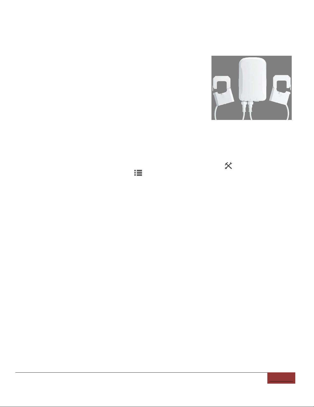
4.2 Z Wave Energy Monitoring Installation (Optional)
In addition to collecting data from the system microinverters using power
line communication (PLC), the CP-GWY-100 allows for communication with
select devices over a Z Wave link. The most common application for this is
for energy monitoring with the Aeotec Gen5 Home Energy Meter
(ZW095-A). It allows for the Chilicon system to support production and
consumption monitoring as well as zero export. The Gen5 uses a series of
current transducers which are placed on the power lines to be monitored.
While these transducers must be physically placed on the lines, Chilicon power recommends first pairing the units
with the CP-GWY-100 gateway. This ensures that they are in range of each other with a strong enough wireless
signal. If a weak signal is detected, the ZW117 repeater can be deployed to extend the distance.
To pair the devices:
1) From the home screen, press the Menu button and then the Advanced Settings.
2) Press the “Measurement Setup” button.
3) Enable the Z-Wave communication hardware on the Gateway if that has not been done yet by checking the
box labeled “Enable Z-Wave communication”. A dot inside the box indicates it is active.
4) The next step is to add the HEM to the list of paired devices. Press the “Add” button and then press the button
on the back of the HEM device once.
5) If your meter has been successfully paired to your network, its light will remain solid. If the pairing was
unsuccessful, the light will blink. If that is the case, try repeating the procedure again.
6) Once the HEM is paired, you will be prompted to specify the number of clamps used (usually it will be 2) and
whether the HEM is used for generation metering (PV array only) or consumption (net home metering or any
home appliance).
7) After exiting that window, the new paired device should show up in the list of paired devices. Note that each
HEM is associated with an ID number.
8) The next step is to finish the setup of the meter. Press the “Auto-Setup Meter” button in the bottom left. This
will automatically setup the meter either as a NET METER or as a PV METER. A dialog box will prompt for that
choice at the end of the setup. Note that most users will choose the NET METER option since that enables
consumption monitoring while the PV array monitoring is accomplished by the microinverters themselves. The PV
METER option is only in the case you have an additional meter setup solely for the purpose of measuring a
generating solar array. This is redundant with the monitoring of Chilicon microinverters and would only be used
to monitor should there be a pre-existing array with another manufacturer’s equipment.
9) Finally, install the CT clamps on the actual lines to be monitored. Please note that both the Aeotec Gen5
ZW095-A Home Energy Meter and the ZW117 repeater require 120V AC power to operate.

Chilicon Power Residential Design and Installation Guide 15
Appendices

Typical Single Line Diagram
One branch circuit of 20 x ≤355W modules
10 CP-720 microinverters current limited to 2.4A
Two modules connect to each microinverter
MICROINVERTERS MEET RAPID
SHUTDOWN REQUIREMENTS PER NEC
2017 SECTION 690.12

8 CP-720 microinverters at maximum current
Two modules connect to each microinverter
Typical Single Line Diagram
One branch circuit of 16 x >355W modules
MICROINVERTERS MEET RAPID
SHUTDOWN REQUIREMENTS PER NEC
2017 SECTION 690.12

CP-720 dBC MC4 & MTC CONNECTION PROCEDURE
STEP 1: DC CONNECTIONS
IPREV 4.16.20A
STEP
1:
DC
CONNECTIONS
IMPORTANT:ALWAYSCONNECTDCFIRST.DONOTENERGIZEACBUSTOINVERTERSUNTILALL
INVERTERSHAVEBEENDCPOWEREDWITHENOUGHSUNLIGHT (LEDsblinkingcontinuously).
60/72cellmodules:PlugeachpanelintooneofthetwopairsofMC4connectorsoftheCP720.
Note:ThepairfurtherAWAYfromtheLEDpowerstheelectronics.
96/128cellmodules:MakeaPARALLELconnectionbetweentwo96or128cellmodulesusinga
2‐1MC4combiningadapter.ThisparallelcombinationshouldbepluggedintotheFIRSTpairof
MC4sontheCP720(furthestfromtheLED).ThesecondpairofMC4sconnectorsontheCP720
shouldbeconnectedtogether(shorted).
STEP 2: AC CONNECTOR – INSTALLATION PROCEDURE
1) JointheintegratedACcablefromthemicroinvertertoatrunkcableT‐Junction.
NOTE:Theconnectorpinsshouldeasilyglideintothesocket.Asmallclickindicatesthatthe
connectorisproperlyseated.
IMPORTANT:donottrytoforceintheconnector!Insertionresistanceindicatesimproper
orientation.Rotatetheconnector180°beforetryingagain.
MBC Cable MBC Cable
MTC C bl
1
2
MTC
C
a
bl
e
1
LED CODES
A
fter DC is a
pp
lied:
BlinkSequence Meaning
Slow,1blinkevery4seconds DCConnected,butMicroNOTREADY forACtobeapplied‐WAIT
Continuousblinking DCConnectedandMicronowreadyforACtobeapplied.
BlinkSequence Meaning
1blink every 8seconds
Normal production, inverter not bound to gateway
pp
After AC is applied:
1
blink
every
8
seconds
Normal
production,
inverter
not
bound
to
gateway
1blinkevery16seconds Normalproduction,inverterboundtogateway
2blinkevery4seconds Microinverterinitializingaftergridpresent‐WAIT
3or4blinksevery4seconds Error‐Gridvoltageoutofrange
5blinksevery4seconds Error‐PVmodulevoltageoutofrange
Chilicon Power LLC | 2019 18

WIRING FOR COMMUNICATION TO THE GATEWAY
Chilicon Power trunk cables have 4 color-coded conductors: RED, BLACK, WHITE, GREEN.
BLACK and WHITE conductors are for the PLC communication. The same grid line (BLACK)
must be used to connect the inverter to the Gateway to ensure robust communication.
Specifically, the Gateway inside the home (120 V) should be powered using GRID HOT LINE B
(= BLACK trunk conductor) and GRID NEUTRAL (= WHITE trunk conductor).
NOTE: Communication with the Gateway is usually fine even if the Gateway is connected in
th ll k t t th
RED
d
WHITE
tk
i l t i H th i l ill b
th
e wa
ll
soc
k
e
t
t
o
th
e
RED
an
d
WHITE
t
run
k
-equ
i
va
l
en
t
w
i
res.
H
owever,
th
e s
i
gna
l
w
ill
b
e
weaker (- 10 dB). The Gateway socket survey screen indicates the strength of the signal. In the
worst case, you simply have to swap the RED and BLACK trunk wires on the breaker or at the
AC disconnect.
NOTE: Miswiring AC grid lines to the inverter trunk (for instance swapping a GRID L1 for GRID
NEUTRAL) will not damage the inverters. However, they will not export power in this
ff ff
con
f
iguration. I
f
inverters are miswired, LED single blink export con
f
irmation
f
rom the LED will
never be established.
WARNING:NEVER CONNECT GREEN to a Live Wire
Max 8 CP720/String (16 Modules)
240V full current
Solar AC Subpanel
Max
8
CP720/String
(16
Modules)
–
240V
full
current
Max10CP720/String(20Modules)– 240V@2.4Acurrentlimit
Max7CP720/String(14modules)– 208Vfullcurrent
Solar
AC
Subpanel
GRID NEUTRAL WHITE
10AWG JBox
GRID L2 BLACK Conductor (PLC Phase)
GRID L1 RED Conductor
GROUND GREEN Conductor
10AWG
JBox
Chilicon Power LLC | 2019 19

GATEWAY COMMISSIONING PROCEDURE
GCREV20.01
Step 1: Plug in the gateway
Step 2: Establish the communication link
•Select“Menu>Wifi Setup”andenterthecustomerswifi information
•Thisstepisnotrequiredifdirectlyconnectingwithanethernet cabletothecustomer’snetwork.
•Note:Chilicon recommendsadirectethernet connectionwheneverpossible.
Step 4: Register the system
•
Select
“
Menu
>
Advanced
Settings
>
Cloud
Setup
”
to register the site to the
Chilicon
cloud
Step 3: Select/confirm time zone
•Select“Menu>Preferences>SetTimeZone”
•Select“OK”forPacificTime,otherwisechangefromthepulldownmenuandthenselect“OK”
Step 5: Perform a socket survey (PLC strength test)
•Select“Menu>AdvancedSetting>SurveySocket”.Checktoseethata90%+signalisreceived
ontheproperphase.ThisindicatesthatthegatewayisonthesamephaseasthePLCsignal.
•
If
not
you can either switch the gateway to an outlet
in the house that
is on the same phase
Select
Menu Advanced
Settings Cloud
Setup
to
register
the
site
to
the
Chilicon
cloud
monitoringsystem(enterthecustomerinformationandemail,installerinformationandemail)
•NOTE:Pleasedoublecheckforthecorrectemailaddress.Anincorrectaddresswillnot
immediatelygenerateanerrormessagebutwillpreventthecustomerfromconnecting.
•
If
not
,
you
can
either
switch
the
gateway
to
an
outlet
in
the
house
that
is
on
the
same
phase
asthePLCsignalorswapL1withL2inthecombinerpaneltoswitchthephasing.
Step 6: Find inverters
•Select“Menu>InverterWizard”.Enterthenumberofinvertersinstalledinthesystem.
•ChooseSplitPhaseorTriPhasedependingonsystem
•Waitfortheinverterstobefoundandbind(1beepforeverymicrofound)
St 8 R i t ti fi ti
Step 7: Design array
•Clickonthedialonthehomesplashpagetoeditlocationofpanels
•Followtheinstructionswithinthedialtocreatepanelstoassigntoeachmicro.
•IfusingCP720,panelswillneedtobe"twinned"sothat2panelsgoto1microinverter.
•IfusingCP250,1panelpermicroissufficient.
•Note:ThearraycanalsobedesignedbyloggingintotheChilicon Powermonitoringportal.
St
ep
8
:
R
eg
i
s
t
ra
ti
on con
fi
rma
ti
on
Chilicon Power LLC | 2020
•Havethecustomerchecktheiremailandgetsignedintocloud.chiliconpower.comsothat
theycanmonitorthesystemfromacomputeraswellasthetouchscreen.
Foradditionalassistance,pleasecontactSupportat(310)8001396option2
20
This manual suits for next models
1
Table of contents
Popular Inverter manuals by other brands


Dolmar
Dolmar GE-1100 instruction manual

YASKAWA
YASKAWA GPD 505/P5 troubleshooting manual

Westerbeke
Westerbeke 8 BCDT-614 Specifications

SIIG
SIIG HDMI 2.0 4K HDR user manual

Velleman Instruments
Velleman Instruments PCG10 Reference manual

SMA Solar Technology
SMA Solar Technology STP 15000TL-30 Quick reference guide


