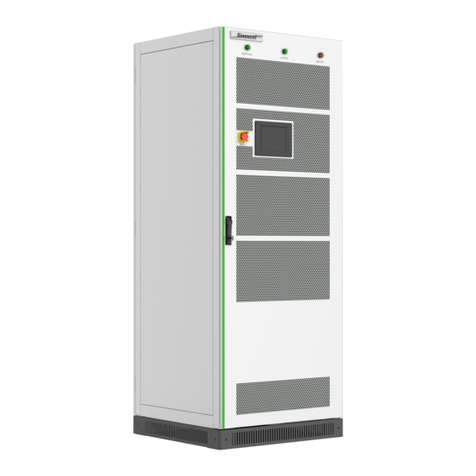
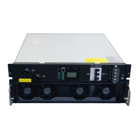
Sinexcel PWD-100M User manual

PWD-100M
User Manual
Ver 1.00


Sinexcel PWD-100M Intelligent Switching Box
User's Manual
Data Version V1.0
Date of filing 2022-10-23
BOM code
Applicable to PWD-100M
Shenzhen Sinexcel Electric Co., LTD provides a full range of technical support to customers, users can
contact the nearest office or customer service center of Shenzhen Sinexcel Electric Co., LTD
Shenzhen Sinexcel Electric Co., LTD
All rights reserved. Contents are subject to change without notice.
Shenzhen Sinexcel Electric Co., LTD
Company website: www.sinexcel.com
Address:Block 6, Block 2, Nanshan Baiwangxin Hi-Tech Industrial Park, No.1002 Songbai Road,
Nanshan District, Shenzhen, China
Postcode:518055
Customer Service Hotline:0755-8651-1588
Company Fax:0755-8651-3100
E-mail: service@sinexcel.com


Contents
Chapter 1 Overview ................................................................................3
1.1 Model Definition................................................................................................................................................................3
1.2 Explanation of symbols ......................................................................................................................................................3
1.3 Safety Instructions .............................................................................................................................................................4
1.3.1 Safety instructions in mechanical installation.............................................................................................................5
1.3.2 Safety instructions in electrical connection ................................................................................................................5
1.3.3 Safety instructions for the switch box in operation ....................................................................................................5
1.3.4 Repair and Replacement Safety Instructions ..............................................................................................................6
1.3.5 Other ..........................................................................................................................................................................6
1.4 Precautions ........................................................................................................................................................................7
1.4.1 Personnel requirements .............................................................................................................................................7
1.4.2 Equipment use range..................................................................................................................................................7
1.4.3 Enclosure marking ......................................................................................................................................................7
1.4.4 Instructions.................................................................................................................................................................7
Chapter2 Product Introduction .....................................................................8
2.1 SystemApplication..............................................................................................................................................................8
2.2 Technical parameters .........................................................................................................................................................8
2.3 Dimension........................................................................................................................................................................10
2.4 Function Description........................................................................................................................................................13
Chapter 3 Equipment Installation .................................................................15
3.1 Transport and Storage......................................................................................................................................................15
3.2 Open Box Inspection........................................................................................................................................................15
3.2.1 Overview...................................................................................................................................................................15
3.2.2 Packing list ................................................................................................................................................................15
3.3 Installation requirements.................................................................................................................................................16
3.3.1 Environmental requirements....................................................................................................................................16
3.3.2 Carrier requirements ................................................................................................................................................16
3.3.3 Other requirements..................................................................................................................................................17
3.4 Equipment installation.....................................................................................................................................................17
3.5 Electrical connection........................................................................................................................................................18
3.5.1 System configuration ................................................................................................................................................18
3.5.2 System grounding .....................................................................................................................................................18
3.5.3 Cableconnection.......................................................................................................................................................18
3.5.4 Connecting communication lines..............................................................................................................................20

IITable of Contents
3.5.5 Dry node connection ................................................................................................................................................21
3.6 Post-installation check .....................................................................................................................................................22
Chapter 4 Commissioning Operation ................................................................23
4.1 Working State Description ...............................................................................................................................................23
4.2 Control method................................................................................................................................................................25
4.3 Backstage display description ..........................................................................................................................................26
4.3.1 Event logging interface display .................................................................................................................................26
4.4 Switching on and off ........................................................................................................................................................28
4.4.1 Pre-boot check..........................................................................................................................................................28
4.4.2 Grid connection procedure.......................................................................................................................................28
4.4.3 Off-grid steps ............................................................................................................................................................30
4.4.4 Shutdown procedure ................................................................................................................................................31
4.4.5 Emergency shutdown ...............................................................................................................................................31
4.4.6 Parallel operation......................................................................................................................................................31
Chapter 5 Communication mode .....................................................................32
5.1 EMS communication ........................................................................................................................................................32
5.1.1 Ethernet port ............................................................................................................................................................32
5.1.2 RS485 serial port.......................................................................................................................................................32
5.2 PWD-100M andPCS cascade networking.........................................................................................................................32
5.3 PWD-100M and multiple PCS are connected to the same network ................................................................................33
Chapter 6 Maintenance ............................................................................34
6.1 Maintenance....................................................................................................................................................................34
6.2 Power circuit connection maintenance............................................................................................................................34
6.3 System working condition maintenance..........................................................................................................................34
6.4 Cleaning and sanitation....................................................................................................................................................35
Appendix .........................................................................................36
Appendix I: Quality assurance and after-sales service.................................................................................................................36
Installation record ..............................................................................38

Chapter 1 Overview
1.1 Model Definition
This section presents the product model definitions covered in the manual as shown in Figure 1-1.
PWD-100M-O
Power 100kW
Power Switch Device
Module
Outside
Figure 1-1 Model Number Definition
Description.
PWD-100M indicates power switching equipment with a module rated capacity of 100kW also known as PWD-100M
intelligent switching box.
PWD-100M-O indicates outdoor power switching equipment with a module rated capacity of 100kW.
The two models have some differences in appearance.
1.2 Explanation of symbols
The following is a list of the identifiers applied in this manual. Please read carefully and understand the meaning
represented by each symbol.
This instruction indicates that there are hazards during operation and that failure to comply
with such warning messages will directly result in serious personal injury or death.
This instruction indicates that there are potential hazards during operation and that failure to
comply with such warnings may result in personal injury or death.
This instruction indicates that there is a potential hazard during operation and that failure to
follow such warnings may result in equipment damage.
DANGER
WARNING
CAUTION

4Chapter 2Introduction to PCS-AC, STS modules
"Instructions" are additional information in the manual, highlighting and supplementing the
content, and may also provide tips or tricks to optimize the use of the product, helping you to
efficiently solve some of the problems in the application.
1.3 Safety Instructions
This manual covers the installation and use of the PWD-100M Intelligent Switching Box from Sinexcel Electric.
⚫The PWD-100M Smart Switch Box must be commissioned and maintained by an engineer appointed
by the manufacturer or its agent. Otherwise, it may endanger personal safety and cause equipment failure, and the
resulting damage to the equipment is not covered by the warranty.
⚫PWD-100M intelligent switching box is for commercial/industrial use only.
⚫The PWD-100M Smart SwitchBox is designed and tested in strict accordance with relevant
international safety standards, and its installation, commissioning, operation and maintenance processes must
comply with the Code of Practice for the Safety of Electrical and Electronic Equipment. Improper use or misuse may
endanger the personal safety of the operator or third parties, as well as damage the converter or other property
safety. To avoid this, the following safety precautions must be strictly observed during operation and maintenance,
which are described in detail in the respective sections.
All installation, commissioning and maintenance operations must be performed by
qualified personnel. Professional technicians must meet the following conditions.
⚫An engineer appointed by the manufacturer or its agent.
⚫Have received professional training.
⚫A complete reading of this manual and familiarity with safety matters in
the operation of electrical and electronic equipment.
⚫Be familiar with the relevant safety codes for electrical systems.
Misuse of the equipment poses a risk of injury!
⚫must always follow the instructions in the manual when moving and
placing the machine.
⚫Improper operation of the equipment may result in electric shock, burns,
contusions, etc.
⚫Damage to the equipment caused by any private modification and split
system (or equipment) operation without permission is not covered by the warranty.
CAUTION
CAUTION

1.3.1 Safety instructions in mechanical installation
⚫Damage to the equipment caused by any unauthorized modification and
disassembly of the system (or equipment) is not covered by the warranty.
⚫Always make sure that the converter is free of any electrical
connections before installing the Smart Switch Box!
⚫Poor ventilation of the installation environment will affect the performance of the system!
⚫Good ventilation needs to be ensured during the operation of the equipment. The unit
must be kept upright and the air ducts smooth, with no strong air currents blocking
the air flow near the air outlet to ensure adequate cooling inside the unit.
1.3.2 Safety instructions in electrical connection
⚫Before making electrical connections, it is important to be safe and not to touch the
metal terminals without adequate protection.
⚫The cables used in the electrical system must be securely connected, well insulated and
of proper gauge.
⚫All electrical installations must meet national/regional electrical standards.
⚫Permission must be obtained from the electricity authority of the country/region in which
the installation is located in order to be connected to the grid.
⚫Before connecting to the input power, be sure to ground it reliably and comply with local
electrical standards.
1.3.3 Safety instructions for the switch box in operation
⚫Any touching of the copper strip, contacts, terminals, etc. inside the equipment
connected to the grid circuit may result in a fatal burn or electric shock!
⚫Do not touch the terminals and conductors connected to the grid circuit.
⚫Pay attention to any instructions and safety instruction documents regarding connection
to the grid.
⚫There may be a risk of electric shock inside the device! Donot open theSmart Switch
Box housing while the Smart Switch Boxis in operationor under power.
⚫Only an intact and closed box enclosure protects the operator's personal property.
DANGER
CAUTION
DANGER
WARNING
CAUTION
DANGER
WARNING

6Chapter 2Introduction to PCS-AC, STS modules
⚫any operation of this equipment needs to be performed or directed by a professional.
⚫Please note the safety precautions listed in the user manual and other documents.
1.3.4 Repair and Replacement Safety Instructions
Improper maintenance of the equipment may result in injury or damage to the equipment.
Before performing any operation, the user must strictly follow the following steps.
⚫(a) First disconnect the disconnect switches on the grid side, PCS side and load
side of the intelligent switching box.
⚫Wait at least 5 minutes until the internal energy storage components are
discharged, during which time it is strictly forbidden to touch the equipment terminals,
contacts, copper row and other electrically charged parts with human body or any
conductor.
⚫Use testing equipment to verify that no voltage or current is present.
⚫Do not allow unrelated personnel to enter the maintenance site!
⚫Temporary warning signs must be posted or barriers erected during electrical
connection and maintenance work to prevent entry of unrelated persons into the
electrical connection or maintenance area.
⚫Restart the intelligentswitching boxonly after troubleshooting faults affecting the safety
performanceof theintelligent switching box.
⚫The Smart SwitchBox does not contain maintenance parts inside, so if you need any
maintenance service, please contact our after-sales service personnel.
⚫Please do not replacethe internal components ofthe Smart Switch Box without
permission. Our company will not be responsible for any warranty and joint and
several liability for the resulting damage.
⚫Contact or improper handling of printed circuit boards or other electrostatic sensitive
components can result in damage to the device.
⚫Avoid unnecessary contact with the circuit board.
⚫Observe electrostatic protection codes and wear anti-static bracelets.
1.3.5 Other
All safetymarkings, warning labels and nameplates on the Smart Switch Box.
⚫Must be clearly visible.
⚫Must not be removed or covered.
DANGER
CAUTION
CAUTION
CAUTION
CAUTION
WARNING

1.4 Precautions
1.4.1 Personnel requirements
The PWD-100M intelligentswitching box must be commissioned and maintained by the manufacturer or its agent's
designated engineer. Otherwise, it may endanger personal safety and cause equipment failure, and the resulting damage to
the equipment is not covered by the warranty.
1.4.2 Equipment use range
The PWD-100M intelligent switchingbox is for commercial/industrial use only and may not be used as any energy saving
equipment associated with life support equipment.
1.4.3 Enclosure marking
Thechassis markings contain important information for safe operation of the cabinet and are strictly prohibited from being
torn or destroyed.
Makesurethe chassis marking is clearly readable and replace it immediately if it appears damaged or blurred.
1.4.4 Instructions
To facilitate the user to read this manual more easily, the manual is equipped with a large number of pictures. The
pictures are for illustration purposes only. The actual product shall prevail for specific information about the product.

Chapter2 Product Introduction
2.1 SystemApplication
Intelligent switching equipment is usually connected between grid, PCS and load at the same time, used to dispatch the
power configuration between the three, grid can be composed of low-voltage distribution network or a small range of oil
machine power supply network, the load is local load for industrial and commercial use, when there is a fault in the grid, it can
be switched off the grid through PCS to realize grid and load switching, when PCS has a fault, cut off the connection between
grid and PCS to ensure normal operation of the load.
Figure 2-1 Intelligent switching topology diagram
2.2 Technical parameters
Table 2-1 shows the detailed technical parameters of PWD-100M intelligent switching box.
Table 2-1 technical parameters table
Indicator Item \ Model
PWD-100M
System parameters
Rated power
100kVA
Rated voltage
Single-phase: 220VAC/230VAC/277VAC
Three-phase: 380VAC/400VAC/480VAC
Rated frequency
50Hz/60Hz
Rated input current
145A
Parallel and off-grid
switching time
<30ms
PWD100
Grid
Breaker
PCS
Breaker
PCS
Breaker
PCS
Aux1
MCU1
MCU2
Breaker
BI
load
CT
KM1 KM2
N1
N2
NPE
Breaker
Aux2
CT

Chapter 3System Introduction9
Protection grade
IP20
Design life
10 years
Cooling method
Air-cooled
Grid access
1 way (no more than 100kW)
PCS access
1 way (no more than 90kW)
Load access
1 way (no more than 90kW)
Number of inverters
3 unitsPWS2-(29M,30M)-EX
Wiring method
Three-phase four-wire system / Three-phase three-wire system
Communication
method of upper computer
ModBus, TCP/IP protocol
Communication
interface
CAN*2/RS485*4/WIFI*1/LAN*2
Dimension
440*580*175mm
Noise
70dB
Temperature range
-25℃~ +50℃
Altitude
3000m
Humidity
0~100%
Weight
25KG
Installation method
Wall/rack type
DI
6
DO
4
Indicators
Run, fault, power
Wiring terminals
DT terminal (M8)
Protection
System protection: over temperature, AC over-voltage, AC reverse sequence, emergency
stop, fan failure, output overload.
Safety protection conditions can be set, setting parameters include: AC voltage protection
upper limit, AC voltage protection lower limit, AC frequency protection upper limit, AC frequency
protection lower limit.
Indicator items \
Models
PWD-100M-O
System parameters
Rated power
100kVA
Rated voltage
Single-phase: 220VAC/230VAC/277VAC
Three-phase: 380VAC/400VAC/480VAC
Rated frequency
50Hz/60Hz
Rated input current
145A
Parallel and off-grid
<30ms

switching time
Protection class
IP65
Design Life
10 years
Cooling method
Air-cooled
Grid access
1 way (no more than 100kW)
PCS access
1 way (no more than 90kW)
Load access
1 way (no more than 90kW)
Number of inverters
3 unitsPWS2-(29M,30M)-EX
Wiring method
Three-phase four-wire system / Three-phase three-wire system
Communication
method of upper computer
ModBus, TCP/IP protocol
Communication
interface
CAN*2/RS485*4/WIFI*1/LAN*2
Dimension
440*580*175mm
Noise
70dB
Temperature range
-25℃~ +50℃
Altitude
3000m
Humidity
0~100%
Weight
31.5KG
Installation method
Wall/rack type
DI
6
DO
4
Indicators
Run, fault, power
Wiring terminals
DT terminal (M8)
Protection
System protection: over temperature, AC over-voltage, AC reverse sequence, emergency
stop, fan failure, output overload.
Safety protection conditions can be set, setting parameters include: AC voltage protection
upper limit, AC voltage protection lower limit, AC frequency protection upper limit, AC frequency
protection lower limit.
2.3 Dimension
PWD-100M intelligent switching box outline dimensions as shown in Figure 2-1, chassis length 580mm, width 440mm,
height 173. 8mm.
PWD-100M-O intelligent switching box outline dimensions as shown in Figure 2-3, chassis length 920mm, width 440mm,
height 205mm.

Chapter 3System Introduction11
Figure 2-1 PWD-100M intelligent switching box dimensions
1
234
5
Figure 2-2 PWD-100M front panel
Table 2-1 PWD-100M front panel description
Serial
number
Name
Description
1
Grounding
terminal
Grounding protection wire fixed point

2
Grid terminal
Connection to the grid
3
Load side terminal
Connects tothe load
4
PCS side terminal
ConnectPWS2-(29M,30M)-EX module
5
Signal interface
area
External communication port
Figure 2-3 PWD-100M-O Intelligent Switching Box External Dimensions
6
1
2 3 4
5
7

Chapter 3System Introduction13
Figure 2-4 PWD-100M-O front panel
Table 2-2 PWD-100M-O front panel description
Serial
number
Name
Description
1
Pneumatic
pressure reducing
valve
Prevents expansion when the internal temperature of the module is high
2
Grid terminal
Grid side inlet baffle (remove this baffle during installation)
3
Load side
terminals
Load side inlet baffle (remove this baffle during installation)
4
PCS side terminal
block
PCS side inlet baffle (remove this baffle during installation)
5
Signal line
waterproof terminal
External communication port
6
Grounding
terminal
Grounding protection wire fixed point
7
Handle
For chassis support
2.4 Function Description
The functions of the PWD-100M intelligent switching box can be basically summarized as follows.
On-grid active cut off-grid: When PCS module PWS2-(29M,30M)-EXwith PWD-100M intelligent switching box
systemworks in the on-grid state, if the user takes the initiative to set off-grid, the system switches off-grid operation, at which
time the load is carried by PCS alone.
Off-grid active cut to grid: When PCS module PWS2-(29M,30M)-EX modulewith PWD-100M intelligent switching box
systemis working in the grid-connected state, if the user actively set the grid-connected, the system switches to
grid-connected operation, and the load is driven by PCS and the grid together at this time.
When the PCS module PWS2-(29M,30M)-EX module with PWD-100M intelligentswitching box system is workingin
grid-connected state, if abnormal condition of the grid is detected, the system will automatically switch to off-grid operation,

and the load will be driven by PCS alone; if the grid is back to normal, the system will automatically return to grid-connected
operation, and the load will be driven by PCS and the grid together.
Data storage: PWD-100M intelligent switching box stores operation information, operation records, fault records and
other information.
Communication function.
⚫The standard RS485 interface can be connected with EMS and other monitoring equipment.
⚫The standard Ethernet interface is used to communicate with the host computer to achieve remote control,
remote software upgrade and other functions.
⚫Standard CAN interface can be used for parallel communication with PWS2-(29M,30M)-EX.
Protection functions.
⚫Overcurrent protection
⚫Overload protection
⚫Short circuit protection
⚫Simultaneous failure protection
⚫Environmental over-temperature protection
⚫Grid voltage monitoring
⚫Grid frequency monitoring
⚫Anti-islanding protection
⚫Redundant protection functions in accordance with VDE certification

Chapter 4 Equipment Installation15
Chapter 3 Equipment Installation
3.1 Transport and Storage
When transporting andstoring the SmartSwitch Box, please pay attention to the marking on the box. The following
requirements should be met during transport and storage.
⚫Do not removethe outer packagingof the Smart Switch Box.
⚫No corrosive gases in the surroundings.
⚫Storage temperature maintained at -40℃~65℃and relative humidity maintained at 0%RH~95%RH.
⚫Non-dusty environment.
⚫Periodic inspection is required during storage; if insects and rodents are found, the packaging
material needs to be replaced in time.
⚫Compliance with fire-fighting requirements.
⚫After long-term storage, the converter needs to be inspected and tested by professionals before it can
be put into use.
CAUTION
⚫Cabinets should not be stacked when transported and stored, and other items
are not allowed to be stacked on top.
⚫The cabinet should be placed upright, not upside down or flat.
3.2 Open Box Inspection
3.2.1 Overview
Beforethe PWD-100M intelligent switchingbox is ready for installation, an unpacking inspection should be conducted,
mainly checking the following contents.
⚫Check whether the quantity of each item in the packing list is consistent with the physical object.
⚫Check whether the nameplate data of the product and the ordering contract are consistent, such as the product
model, rated capacity, voltage level, etc..
⚫Check whether the factory documents and accessories are complete.
⚫Whether the chassis is deformed, off-painted and loose.
3.2.2 Packing list
PWD-100M intelligent switching box packinglist is shown in Table 3-1, PWD-100M-O outdoor intelligent switching box
packing list is shown in Table 3-2.
Table 3-1 PWD-100M intelligent switching box packing list

16Chapter 4 Equipment Installation
Seri
al
number
Name
Qua
ntity
Remarks
1
User manual
1
copy
2
External communication terminal
2
pcs
3
WIFI signal enhancement connector
1pc
4
Certificate of Conformity
1
copy
Table 3-2 PWD-100M-O intelligent switching box packing list
Seri
al
number
Name
Qua
ntity
Remarks
1
User manual
1
copy
2
External communication terminal
2
pcs
3
WIFI signal enhancement connector
1pc
4
Fireproof mud
1
copy
5
Certificate of Conformity
1
copy
3.3 Installation requirements
3.3.1 Environmental requirements
⚫Installation indoors, avoiding sunlight, rain and standing water.
⚫Clean installation environment, avoiding large amounts of dust in the air.
⚫Installation position without shaking.
⚫Ambient temperature guaranteed at: -20 to 50°C.
3.3.2 Carrier requirements
⚫Intelligent switching box installation carrier must have fireproof performance.
⚫Please do not install the equipment on flammable building materials.
⚫Please ensure that the installation surface is sturdy and meets the load-bearing requirements for the installation of
the smart switching box.
Table of contents
Other Sinexcel Inverter manuals
Popular Inverter manuals by other brands

Thermal Arc
Thermal Arc Dragster 80 owner's manual

Mitsubishi Electric
Mitsubishi Electric FR-E720-0.4K instruction manual
FoxESS
FoxESS H1 Series user manual

Mitsubishi Electric
Mitsubishi Electric FR-A700 Series Installation guidelines

Everpower Electronics
Everpower Electronics SD700 Programming and Software Manual

atecpool
atecpool SIROCCO AIHP115 user manual
