Chiltern Invadex OHWLTRK-1 User manual
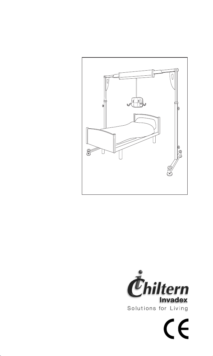
Portable Gantry
Wispa
LiteTrack
LiteTrack
user guide
Gantry System
FM 40009
FM 21085
Q
U
A
L
I
T
Y
•
S
A
F
E
T
Y
•
S
E
R
V
I
C
E
•
LiteTrack
Chiltern Invadex Ltd
6Wedgwood Road
Bicester Oxfordshire
OX26 4UL
Tel: 01869 246470
Fax: 01869 247214
Overseas Enquiries
Tel: +44 (0) 1869 365545
Fax: +44 (0) 1869 365567
Web: www.chilterninvadex.co.uk
Chiltern Invadex (NI) Ltd
5Balloo Way
Balloo Industrial Estate
Bangor County Down
BT19 7QZ
Tel: 028 9145 0497
Fax: 028 9127 0046
Chiltern Invadex Ltd
Unit 16 Evans Business Centre
68-74 Queen Elizabeth Avenue
Hillington Industrial Estate
Glasgow G52 4NQ
Tel: 0141 880 9986
Fax: 0141 880 9990
Copyright © Chiltern Invadex Ltd. The design of the product shown in this User Guide is vested in Chiltern Invadex Ltd and should not be copied or
reproduced in anyway whatsoever without the express permission in writing of Chiltern Invadex Ltd.
Published by: Chiltern Invadex Ltd 6 Wedgwood Road Bicester Oxon OX26 4UL Registered in England No: 1182024
In Ireland: Chiltern Invadex (NI) Ltd 5 Balloo Way Balloo Industrial Estate Bangor County Down BT19 7QZ Registered No: 19958
CINV435.01 08/05
23

User Guide
1
Contents
Portable Gantry System
This product has been designed to the highest
standards with safety, strength and quality in
mind.
Follow the recommendations in this guide to
ensure maximum benefit from your Wispa
LiteTrack Gantry system. Should you
experience any difficulties please consult the
trouble shooting guide, prior to contacting your
LiteTrack Gantry supplier.
Read the safety section of this guide prior to
use, this is contained on page 2.
Intended use of the Product .............................. 2
Things to consider before using the
Gantry ................................................................ 2
Assembly Guide ................................................ 4
Disassembly guide .......................................... 11
Servicing & maintenance ................................ 15
Parts ................................................................. 15
Troubleshooting ............................................... 16
Gantry Specification ........................................ 17
Warranty .......................................................... 18
Gantry Service Record ................................... 19
Chiltern Invadex LiteTrack Portable Gantry
20
Gantry Service Record
Serviced By
(company) .......................................................................................
Telephone no....................................................................................
Engineers training cert. no. Signature
................................................................ .................................
Date: .............................. Load Tested To: .............................Kgs
Comments..........................................................................................
...........................................................................................................
Serviced By
(company) .......................................................................................
Telephone no.......................................................................................
Engineers training cert. no. Signature
...................................................................... .................................
Date: .............................. Load Tested To: ..........................Kgs
Comments .........................................................................................
...........................................................................................................

Chiltern Invadex LiteTrack Portable Gantry
2
•
Only a single hoist should be attached to the gantry at
any one time
•
Do not operate the WispaLite Portable Hoist and gantry
without training in the safe operation of the hoist,
gantry and slings. The gantry should only be assembled
by a competent person.
•
Only use slings which have been assessed as
suitable by a competent person.
•
Read the Wispa Lite Portable hoist User Guide in
conjunction with this guide.
•
Read the relevant Sling User Guide, which is
provided with each sling. It explains in detail how to
use slings correctly.
•
Do not use the Gantry if there is any doubt about the
integrity of the gantry, wear to the hoist carry bar or
there is fraying or stitch damage to the lifting tape or
slings, or if the gantry or hoist itself is damaged in any way.
•
Do not exceed the Maximum load of the gantry or hoist.
Wispa LiteTrack Gantry 210kgs (33 Stone) (460 lb)
WispaLite Portable Hoist 200kgs (31 Stone) (440 lb)
•
Ensure when the gantry and hoist are in use that
the surrounding area is clear and the person being
lifted is clear of all objects.
•
Always ensure the gantry is assembled and
adjusted for level using the spirit levels on the end beams.
•
There are only 3 width adjustment holes per end
beam. The pin must always be located in one of these.
Safety
Safety Considerations
Intended Use of the Product
The Wispa LiteTrack gantry sytem has been designed to lift and transfer
aless able person with the help of a carer. The gantry is portable and
can easily be relocated and reassembled wherever required. It should be
used with the WispaLite Portable Hoist and a Wispa sling or other lifting
accessories from the Chiltern Invadex range, as assessed by a trained person.
Note: Not all slings and accessories are compatible with the Wispa Lite hoist.
If you are unsure please contact your nearest Chiltern Invadex Office.
The correct and appropriate use of this product will reduce the risks
associated with manual patient handling. The lifting/transferring task should
be assessed and planned by a trained person.
User Guide
19
Gantry Service Record
Serviced By
(company) .......................................................................................
Telephone no....................................................................................
Engineers training cert. no. Signature
................................................................ .................................
Date: .............................. Load Tested To: .............................Kgs
Comments..........................................................................................
...........................................................................................................
Serviced By
(company) .......................................................................................
Telephone no.......................................................................................
Engineers training cert. no. Signature
...................................................................... .................................
Date: .............................. Load Tested To: ..........................Kgs
Comments .........................................................................................
...........................................................................................................
Serviced By
(company) .......................................................................................
Telephone no.......................................................................................
Engineers training cert. no. Signature
...................................................................... .................................
Date: .............................. Load Tested To: ..........................Kgs
Comments .........................................................................................
...........................................................................................................

User Guide
3
•
Always ensure the gantry track is directly above
the clients centre of gravity. Hoists should only be
used to lift vertically. Lifting at an angle will wear
the lifting tape prematurely and affect the stability
of the gantry.
•
Always ensure the top beam is horizontal and the
leg adjustment pin is located in the same position
on each side.
•
All fixings should be checked on a regular basis.
•
The cassette case and mechanical parts should
only be removed by a qualified service engineer,
trained by Chiltern Invadex.
•
Do not touch any of the moving parts in the hoist
unit or in the track. Call Chiltern Invadex for assistance.
•
Always ensure the legs are positioned as shown
in Fig 13 of this user guide
•
Take care when moving around the gantry to avoid
trip hazards such as the legs, handwheels and
potential injury from the corner quadrant.
•
Take care when attaching or removing a sling as a
swinging carry bar or hoist could cause injury.
•
For maximum comfort always move the user in one
movement and avoid stop/starting the hoist.
Some occupants are reassured if the carer holds
them whilst the hoist is traversing across the track.
•
Never leave a client unattended on the gantry.
•
Keep this user guide readily available for other users.
•
Always ensure there is sufficient clearance width
and height to erect/dismantle the gantry.
•
If the gantry is to be dismantled always remove the
Wispa Lite portable hoist from the gantry before
attempting to dismantle the gantry. The hoist should
be lowered onto a bed, chair or a Chiltern Invadex
transportation trolley before it is disconnected from
the gantry track.
•
Always follow the assembly/dissassembly
instructions contained in this guide.
After use
Chiltern Invadex LiteTrack Portable Gantry
18
Warranty
Your Chiltern Invadex Wispa LiteTrack Gantry carries a 2 year warranty
from the date of purchase, subject to the following :-
1. Should you experience any problems with our workmanship
or materials within the first 2 year period please contact
your point of purchase.
2. Repairs made during the warranty period will be carried out
free of charge, provided the product has been used strictly
in accordance with the guidelines set out in this user guide.
3. Our warranty does not cover replacements, adjustments or
repairs which may be required as a result of normal wear
and tear, wilful or accidental damage, misuse, neglect or
any other cause which is beyond the control of
Chiltern Invadex.
4. Modifications and repairs made to this product by
unauthorised persons will render the warranty void.
5. Only parts manufactured or approved by Chiltern Invadex
shall be used to repair this product. Use of unauthorised parts
will invalidate all warranties and remove all liability from
Chiltern Invadex for the safety of this product.
6. Chiltern Invadex shall in no event be liable for any damages,
costs or expenses arising from any claim made under this
warranty (save for any legal liability of Chiltern Invadex for
death or personal injury resulting from the company’s
negligence in respect of its products).
7. This warranty does not affect your statutory consumer rights.

Chiltern Invadex LiteTrack Portable Gantry
4
Check all components are available prior to assembly.
Notes:
If the gantry is to be assembled over a bed
The gantry can be assembled over a bed unless it is occupied. If the
bed is occupied assemble the gantry away from the bed and then
position afterwards (as a guide this would be approximately 900mm
from the head board but always ensure the gantry track is directly
above the clients centre of gravity).
1. Preparation
1. Unpack all components and lay on the floor ready for assembly.
2. Check all parts are available (see Fig 1) and for damaged components.
3. Safety note: The corner quadrant located on the end beam (see Fig 1)
should always have tension. Check to ensure it does not swing freely
and there is tension.
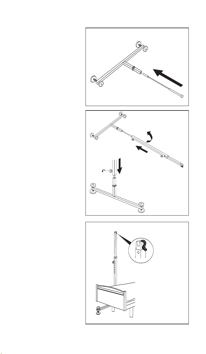
2. Leg assembly
Loosen both black handwheels on the leg as Fig 2 (C & D). Push both
release levers in with one hand as Fig 2 (A), pull out the inner leg
section to the first position as Fig 2 (B) having let go of the release
levers. This should then ‘click’ into place (the pin will be flush with the
top of the block when in the correct position). Secure the leg with the
locking knob Fig 2 (C). Note: The height of the unit can be adjusted later
when the gantry is fully assembled.
AA
A
B
C
D
LiteTrack Gantry Assembly
Instructions
Fig 2
Foot section x 2
Leg section x 2
Cassette x 1
End beam x 2
Foot section x 2
Leg section x 2
Cassette x 1
Gas strut x 2
Corner
quadrant x 2
Fig 1
User Guide
17
Lifting capacity 210 Kg (33 stone)(460 lb)
including hoist
Construction Legs - steel
Track - Aluminium
Cassette - Aluminium with ABS cover
Lifting Range Approximately 1525mm - 1825mm
Maximum loading per foot 100kg (16 stones) (220lb) (provided that the gantry is used in
accordance with the instructions in this user guide)
Assembled component weights:
Lower Leg section (x2) 7kg each (15.5lb)
Upper Leg section 8kg each (18lb)
Cassette (x1) 11kg (24lb)
End section/corner quadrant (x2) 5kg each (11lb)
Gas strut (x2) 1kg each (2.2lb)
Total weight of gantry 53kg (116lb)
CE MARK
The Chiltern Invadex Wispa LiteTrack Gantry carries the CE mark and complies with EC Directives:
Medical Device Directive(93/42/EEC)
Further assistance
Please telephone any Chiltern Invadex Office for further assistance.
Remember that service calls made after the guarantee period will be
chargeable. If the maintenance of the equipment is the responsibility of a
third party, for example the Social Services, please contact them in the first
instance.
Gantry Specification
2165 - 2465
(50mm intervals)
1010 - 1530440
Gantry at highest position 1825
Gantry at lowest position 1525
2040 - 2560
1890 - 2410 (Internal)
1100
User Guide
5
3. Locating the leg
and foot sections
and inserting the
gas strut
Where there is limited
head room it is
recommended that
the foot section is
laid on its side for
assembly as Fig 3.
Insert the gas strut in
the orientation shown
in Fig 3.
Place the leg section
over the gas strut as
Fig 3 (B) (Note:
Orientate the leg to
ensure the top catch
bracket is pointing
towards the floor),
while raising the leg
at the same time
(taking care not to
damage the gas
strut), compressing
the gas strut and
pushing down as far
as the moulding on
the foot section as
Fig 3 (C). Note: The
bottom handwheel
needs to be almost
all the way out.
4. The top catch
bracket should be
located on the inside
as Fig 4. Tighten the
lower handwheel to
secure in place.
Safety note: The
leg is not yet free
standing. Do not
leave the leg
unattended. Lay it
on the floor, against
abed or wall.
Repeat for other leg.
Fig 3
Fig 4
Top catch bracket on
leg section facing inward
B
A
Fig 3B
Fig 3C
Chiltern Invadex LiteTrack Portable Gantry
16
symptom suggested cause solution
Troubleshooting
Cassette travels
further in one direction
along the beam than
the other
Pins do not click into
position on the leg
Pins do not click into
position on the end
beam/cassette
Spring mechanism is
stuck on the leg/end
beam section
Spring mechanism has
failed on the leg/end
beam section and will
not push in manually
Height of feet cannot
be adjusted
Cannot check gantry is
level
Lifting eye on cassette
will not come down
Corner quadrant will
not fold back against
the leg
There is no tension in
the corner quadrant
Leg does not raise
easily/falls under gravity
Gas strut will not
compress
Cable tension is
incorrect
Leg section is
incorrectly positioned
End beam section is
incorrectly positioned
Push pin in manually
Spring mechanism is
damaged
Thread on feet is
damaged or twisted
Spirit levels are
damaged or broken
Spring mechanism is
defective/damaged
Gantry leg not positioned
correctly to accept the
corner quadrant.
Corner quadrant is
defective/damaged
Washers in the corner
quadrant are damaged/
defective.
Adjust grub screws
Gas strut is damaged
Gas strut is damaged
Contact Chiltern
Invadex for assistance
Adjust leg position
Adjust end beam
position
If problem persists
contact Chiltern
Invadex for assistance
Contact Chiltern
Invadex for assistance
See replacement parts
list in this booklet.
Contact Chiltern
Invadex for parts.
Contact Chiltern
Invadex for
replacement parts.
Contact Chiltern
Invadex for assistance
Reposition gantry leg
at 90 degrees.
Contact Chiltern
Invadex for assistance
Contact Chiltern
Invadex for assistance.
Check tension
Contact Chiltern
Invadex for assistance
Contact Chiltern
Invadex for assistance
Chiltern Invadex LiteTrack Portable Gantry
6
6. Attaching beam
to leg section
Please note prior to
assembly:
Top catch bracket on
the leg section should
be on the inside to
accept the beam as
Fig 6.
Top catch bracket on
leg section facing inward
Fig 6
B
A
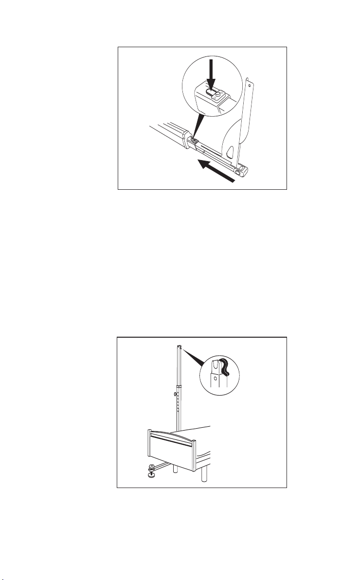
5. Assembling the
cassette and end
beams
Notes:
1. The end beams
which attach to the
cassette are identical.
2. The cassette can be
positioned either way
round.
3. Assemble the
cross beam as close
to the legs as
possible.
Rotate the corner
quadrant to the
position shown in Fig
5. Push the release
lever down with one
hand as Fig 5 (A) and
slide the end beam
into the cassette as
Fig 5 (B) having let go
of the release lever
as the end beam
begins to slide, and
select the appropriate
hole (depending on
lifting task - see p14
for Width calculation
guide). The end beam
will then ‘click’ into
place (the pin will be
flush with the top of
the block when in the
correct position).
Repeat for other side.
Fig 5
User Guide
15
Servicing and Maintenance
Based upon EN10535:1998 and Health and Safety Executive guidance
Chiltern Invadex recommend that hoists and gantry systems are fully
serviced, including a load test, at least every 12 months with an interim
six monthly inspection to LOLER requirements. Prices are available from
Chiltern Invadex Service Offices. The frequency of servicing should be
increased in areas where the environment or heavy usage may cause
deterioration of the equipment. Further details can be obtained from any
Chiltern Invadex Office, shown on the back of this booklet.
Chiltern Invadex and its Authorised Dealers are able to carry out all
aspects of servicing and maintenance work.
Maintenance of this equipment should only be conducted by engineers
trained and certified by Chiltern Invadex.
Keep the service record (at the back of this booklet) up to date.
DO NOT USE IF:
1. There is any damage to the hoist or gantry.
2. There is fraying or stitch damage to the lifting tape, or slings.
3. Any of the gantry parts are missing or damaged
To ensure maximum cleanliness
Wipe with a dry cloth (Gantry and hoist). For stubborn marks use a damp
cloth and a mild cleanser. Always read the manufacturers instructions
prior to applying the cleanser. Avoid using cleaning agents which contain
chlorine, carbolic acid or other strong chemicals as these may damage
the metalwork and plastic components.
Parts
item description qty part no
1 Upright mouldings kit (all mouldings for legs) 1 360-80001
2 Beam mouldings kit (all mouldings for horizontal beam) 1 360-80002
3 Hand Wheel (Black) 1 COM0081
4 Levelling Foot Kit 1 360-80011
5 Spirit Level spares kit (x4 spirit levels) 1 360-80003
6 Gas strut assembly spares kit (x1) 1 360-80004
1
4
Note: Replacement parts should only be installed by trained personnel.
The gantry then needs testing once parts have been replaced.
6
5
2
3
Chiltern Invadex LiteTrack Portable Gantry
14
THGIR
TFEL
eloH
noitisop
123
10981
debelgnislacipyT(
)riahcrewohsot
0
202
debelgnislacipyT(
renilcer/resirot
)riahc
0
512
citsemodlacipyT(
otdebelbuod
)riahcrewohs
20202
debelgnislacipyT(
renilcer/resirot
)riahc
0512
citsemodlacipyT(
otdebelbuod
)riahcrewohs
0822
gnisrunlacipyT(
otdebelbuod
)riahcrewohs
30512
citsemodlacipyT(
otdebelbuod
)riahcrewohs
0822
gnisrunlacipyT(
otdebelbuod
)riahcrewohs
0142
elbuodlacipyT(
otdeb
riahcrenilcer/resir
Width calculation guide
The table below can be used as a quick reference guide to help
determine the internal width of the gantry (depending on the hole position
which has been selected). For example - when the first hole position is
selected on the end beam and the same on the right end beam the internal
width is 1890mm, which will typically allow the transfer of a client from a
single bed to a shower chair).
Dimensions are in mm and for guidance only
User Guide
7
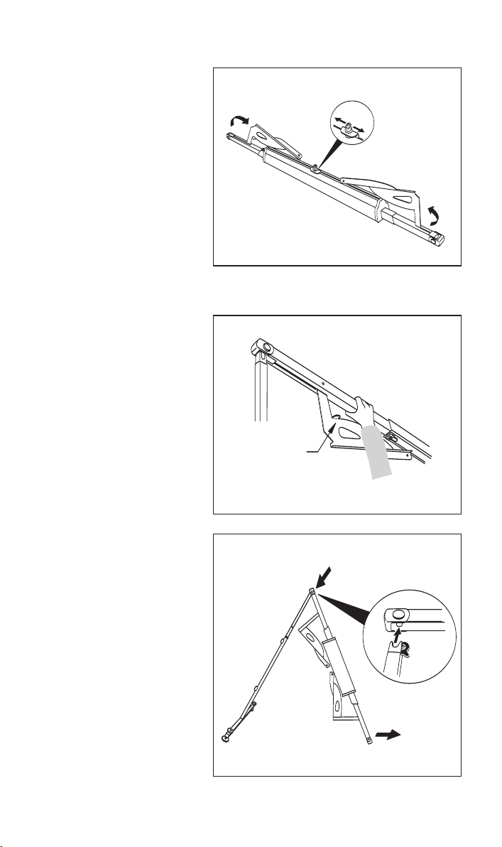
8. General safety
note: When placing
the top beam on the
legs always position
hand behind the
corner quadrant as
Fig 8.1.
Corner quadrant
Note hand grasp point for safety
when assembling beam
Fig 8.2
A
B
Do not lift the whole
cassette section. With
one end of the
cassette resting on
the floor hold the
assembled leg with
one hand, raise the
beam section and
place on top of the leg
as Fig 8.2 (A).
Fig 8.1
7. Fold over the
corner quadrant on
both end beams in
preparation for
connecting to the leg
as Fig 7 (A).
Ensure the cassette is
centralised in the
correct position
(latched). To achieve
this slide along until it
clicks into position in
the centre of the rail
as Fig 7 (B).
Fig 7
A
A
B

Chiltern Invadex LiteTrack Portable Gantry
8
9. Securing the
cross beam to the
cassette
Adjust the position of
the leg as Fig 8.2 (B)
to allow the corner
quadrant to be
connected (this
should be at 90
degrees to the leg and
cross beam).
Pull the corner
quadrant back against
the leg and hold with
one hand against the
leg as Fig 9 (A).
Check the cross
beam has been
locked in position on
the legs. Be aware of
finger trapping hazard
when pulling corner
quadrant back
against the leg.
Secure in position
using the handwheel
as Fig 9 (B).
Fig 9
10. Place the second
leg within easy reach
and raise the end of
the beam. Place on
top of the second leg
as Fig 10. Note:
Check the pin on the
cross beam sits on
top of the moulding on
the legs as Fig 10.
Fig 10
Pull the corner
quadrant back against
the leg (at 90 degrees
to the leg and cross
beam) and hold with
one hand against the
leg as Fig 11 (A).
Secure in position
using the handwheel
as Fig 9 (B).
Fig 11
A
B
A
Pin should sit
on top of the
moulding
User Guide
13
B
A
C
B
C
A
Fig 19
19. Fold back the
corner quadrant as
Fig 19 (A), depress
the release lever as
Fig 19 (B) and slide
out the end beam
section as Fig 19 (C).
Repeat for other side.
20. Leg
disassembly
Where there is limited
head room it is
recommended that
the leg section is laid
on its side for
disassembly as Fig 20.
Loosen the lower
black handwheel as
Fig 20 (A). The gas
strut and leg section
will then slide apart.
Safety note: The
gas strut is
compressed and
will spring out. Pull
the leg section apart
from the gas strut as
Fig 20 (B) and remove
the gas strut from the
foot section (C).
Repeat for other side. Fig 21
Fig 20
B
C
AA
A
21. Ensure top
handwheel is loose
and depress the
release levers as Fig
21 (A) and push the
leg section down to
the lowest position
as Fig 21 (B). Fasten
both handwheels (C)
for safe transportation.
Repeat for other side.
Chiltern Invadex LiteTrack Portable Gantry
12
17. Important safety
note:
1. Completely
remove one leg
BEFORE releasing
the second leg.
2. Ensure there is
sufficient space to
lower the gantry.
Remove the upper
handwheel which
locks the corner
quadrant in place as
Fig 17 (A)
Fold back the corner
quadrant against the
cassette as Fig 17 (B)
one leg at a time.
Push the beam
upwards as Fig 17 (C).
Fig 17
C
BA
Fig 18
Safety note: The
leg is not free
standing. Do not
leave the leg
unattended. Lay it
on the floor,
against a bed or
wall.
18. Lower the beam
to the floor as Fig 18
whilst retaining the
leg with the other
hand.
Repeat for other side.
User Guide
9
Lever NOT correctly
engaged
Lever correctly
engaged
BA
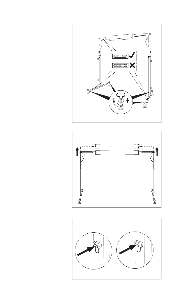
12. Adjusting the
height of the gantry
Position the gantry in
its required location
prior to adjusting the
height and checking
level. Take care when
moving the gantry to
the desired location.
Move one leg at a time
in small increments.
The gantry should be
level in all directions.
Check this using the
spirit levels on the
feet and end beams.
Centre the bubble in
the spirit level
window as Fig 12.
Use the large
handwheels on the
feet to adjust level, as
required as Fig 12.
Fig 12
13. If the height of the
gantry needs to be
raised release the
middle handwheel.
Hold onto the top
handwheel with one
hand, pressing the
release levers in on
the leg with the other
hand, and push the
leg up to the required
height one hole at a
time,raising one leg
and then repeating by
the same increment
on the other side.
Ensure it ‘clicks’ into
position and the pin is
flush with the block
as Fig B. Secure with
the middle handwheel
and check for level
using the spirit levels
on the end beam.
Repeat for other side.
If the leg height is
raised always ensure
adequate clearance
overhead.
Fig 13

Chiltern Invadex LiteTrack Portable Gantry
10
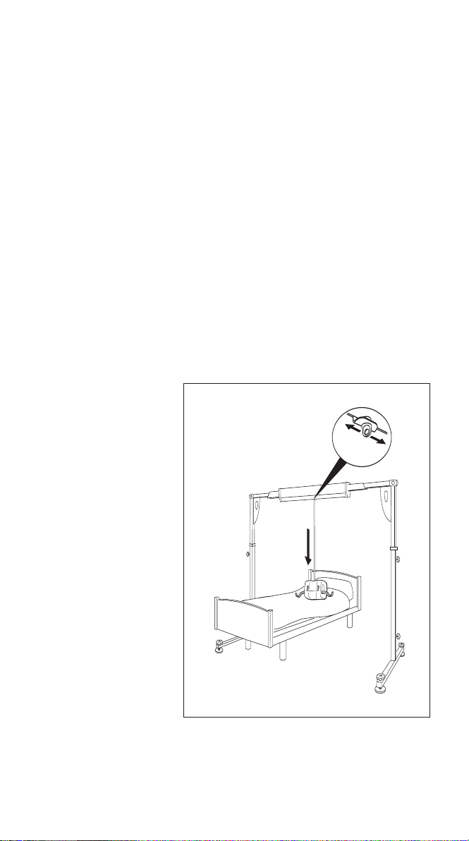
15. Final safety check
Prior to hoisting a client check:
- All handwheels are in place (3 per upright) and they have
been securely tightened
- The gantry is level in all directions
- The height and width of the gantry are appropriate for the
task eg. there is sufficient space to position a wheelchair or
shower chair at the side of the bed for transfer
The gantry is now
ready for use. The
weight of the hoist will
release the cassette
and allow it to travel
freely along the beam
as Fig 15. Slide the
hoist across the
gantry to the desired
position ready to lift/
transfer the client.
Take care when
moving around the
gantry to avoid
trip hazards such as
the legs, handwheels
and potential injury
from the corner
quadrant or cassette.
14. Attaching the
Wispa Lite Portable
hoist
Rest the Portable hoist
on the bed or trolley
ready for attaching to
the eye on the gantry.
Release sufficient
tape to connect the
carabena on the hoist
to the eye on the
gantry as Fig 14. Do
not lift the hoist to
attach it to the gantry.
Fig 14
Fig 15
Final positioning
User Guide
11
16. Disassembly of the gantry
1. Do not lift the hoist. Lower the hoist by releasing sufficient
tape to disconnect the carabena on the hoist from the eye on the
gantry as Fig 16 (B). Remove the hoist from the gantry.
2. Always ensure the cassette is locked in the central position
before disassembling the gantry. To achieve this slide the
cassette along until it clicks into position in the centre of the rail
as Fig16 (A).
If the height of the gantry needs to be lowered release the
middle handwheel. Hold onto the top handwheel with one hand,
pressing the release levers in on the leg with the other hand,
and push the leg down to the required height one hole at a
time,lowering one leg and then repeating by the same
increment on the other side.
3. If the bed is occupied, relocate the gantry to a suitable place
ready for disassembly.
Disassembly of the gantry
A
B
Disassembly of the gantry
Fig 16
Chiltern Invadex LiteTrack Portable Gantry
10
15. Final safety check
Prior to hoisting a client check:
- All handwheels are in place (3 per upright) and they have
been securely tightened
- The gantry is level in all directions
- The height and width of the gantry are appropriate for the
task eg. there is sufficient space to position a wheelchair or
shower chair at the side of the bed for transfer
The gantry is now
ready for use. The
weight of the hoist will
release the cassette
and allow it to travel
freely along the beam
as Fig 15. Slide the
hoist across the
gantry to the desired
position ready to lift/
transfer the client.
Take care when
moving around the
gantry to avoid
trip hazards such as
the legs, handwheels
and potential injury
from the corner
quadrant or cassette.
14. Attaching the
Wispa Lite Portable
hoist
Rest the Portable hoist
on the bed or trolley
ready for attaching to
the eye on the gantry.
Release sufficient
tape to connect the
carabena on the hoist
to the eye on the
gantry as Fig 14. Do
not lift the hoist to
attach it to the gantry.
Fig 14
Fig 15
Final positioning
User Guide
11
16. Disassembly of the gantry
1. Do not lift the hoist. Lower the hoist by releasing sufficient
tape to disconnect the carabena on the hoist from the eye on the
gantry as Fig 16 (B). Remove the hoist from the gantry.
2. Always ensure the cassette is locked in the central position
before disassembling the gantry. To achieve this slide the
cassette along until it clicks into position in the centre of the rail
as Fig16 (A).
If the height of the gantry needs to be lowered release the
middle handwheel. Hold onto the top handwheel with one hand,
pressing the release levers in on the leg with the other hand,
and push the leg down to the required height one hole at a
time,lowering one leg and then repeating by the same
increment on the other side.
3. If the bed is occupied, relocate the gantry to a suitable place
ready for disassembly.
Disassembly of the gantry
A
B
Disassembly of the gantry
Fig 16
Chiltern Invadex LiteTrack Portable Gantry
12
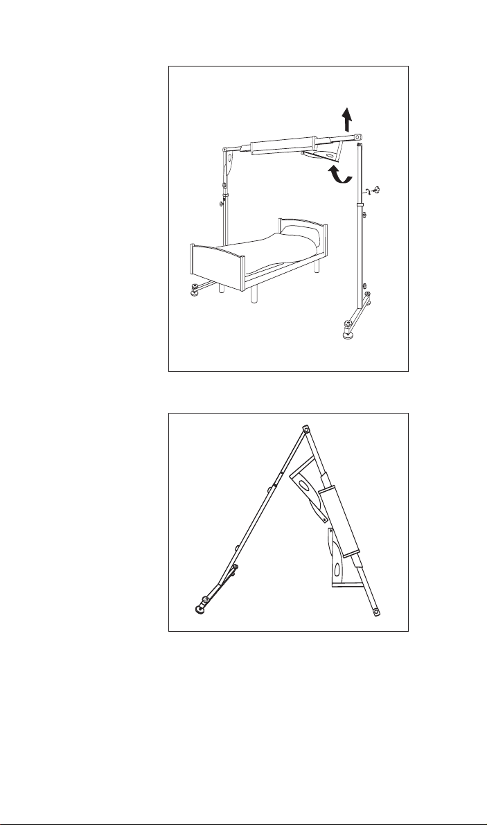
17. Important safety
note:
1. Completely
remove one leg
BEFORE releasing
the second leg.
2. Ensure there is
sufficient space to
lower the gantry.
Remove the upper
handwheel which
locks the corner
quadrant in place as
Fig 17 (A)
Fold back the corner
quadrant against the
cassette as Fig 17 (B)
one leg at a time.
Push the beam
upwards as Fig 17 (C).
Fig 17
C
BA
Fig 18
Safety note: The
leg is not free
standing. Do not
leave the leg
unattended. Lay it
on the floor,
against a bed or
wall.
18. Lower the beam
to the floor as Fig 18
whilst retaining the
leg with the other
hand.
Repeat for other side.
User Guide
9
Lever NOT correctly
engaged
Lever correctly
engaged
BA
12. Adjusting the
height of the gantry
Position the gantry in
its required location
prior to adjusting the
height and checking
level. Take care when
moving the gantry to
the desired location.
Move one leg at a time
in small increments.
The gantry should be
level in all directions.
Check this using the
spirit levels on the
feet and end beams.
Centre the bubble in
the spirit level
window as Fig 12.
Use the large
handwheels on the
feet to adjust level, as
required as Fig 12.
Fig 12
13. If the height of the
gantry needs to be
raised release the
middle handwheel.
Hold onto the top
handwheel with one
hand, pressing the
release levers in on
the leg with the other
hand, and push the
leg up to the required
height one hole at a
time,raising one leg
and then repeating by
the same increment
on the other side.
Ensure it ‘clicks’ into
position and the pin is
flush with the block
as Fig B. Secure with
the middle handwheel
and check for level
using the spirit levels
on the end beam.
Repeat for other side.
If the leg height is
raised always ensure
adequate clearance
overhead.
Fig 13

Chiltern Invadex LiteTrack Portable Gantry
8
9. Securing the
cross beam to the
cassette
Adjust the position of
the leg as Fig 8.2 (B)
to allow the corner
quadrant to be
connected (this
should be at 90
degrees to the leg and
cross beam).
Pull the corner
quadrant back against
the leg and hold with
one hand against the
leg as Fig 9 (A).
Check the cross
beam has been
locked in position on
the legs. Be aware of
finger trapping hazard
when pulling corner
quadrant back
against the leg.
Secure in position
using the handwheel
as Fig 9 (B).
Fig 9
10. Place the second
leg within easy reach
and raise the end of
the beam. Place on
top of the second leg
as Fig 10. Note:
Check the pin on the
cross beam sits on
top of the moulding on
the legs as Fig 10.
Fig 10
Pull the corner
quadrant back against
the leg (at 90 degrees
to the leg and cross
beam) and hold with
one hand against the
leg as Fig 11 (A).
Secure in position
using the handwheel
as Fig 9 (B).
Fig 11
A
B
A
Pin should sit
on top of the
moulding
User Guide
13
B
A
C
B
C
A
Fig 19
19. Fold back the
corner quadrant as
Fig 19 (A), depress
the release lever as
Fig 19 (B) and slide
out the end beam
section as Fig 19 (C).
Repeat for other side.
20. Leg
disassembly
Where there is limited
head room it is
recommended that
the leg section is laid
on its side for
disassembly as Fig 20.
Loosen the lower
black handwheel as
Fig 20 (A). The gas
strut and leg section
will then slide apart.
Safety note: The
gas strut is
compressed and
will spring out. Pull
the leg section apart
from the gas strut as
Fig 20 (B) and remove
the gas strut from the
foot section (C).
Repeat for other side. Fig 21
Fig 20
B
C
AA
A
21. Ensure top
handwheel is loose
and depress the
release levers as Fig
21 (A) and push the
leg section down to
the lowest position
as Fig 21 (B). Fasten
both handwheels (C)
for safe transportation.
Repeat for other side.

Chiltern Invadex LiteTrack Portable Gantry
14
THGIR
TFEL
eloH
noitisop
123
10981
debelgnislacipyT(
)riahcrewohsot
0
202
debelgnislacipyT(
renilcer/resirot
)riahc
0
512
citsemodlacipyT(
otdebelbuod
)riahcrewohs
20202
debelgnislacipyT(
renilcer/resirot
)riahc
0512
citsemodlacipyT(
otdebelbuod
)riahcrewohs
0822
gnisrunlacipyT(
otdebelbuod
)riahcrewohs
30512
citsemodlacipyT(
otdebelbuod
)riahcrewohs
0822
gnisrunlacipyT(
otdebelbuod
)riahcrewohs
0142
elbuodlacipyT(
otdeb
riahcrenilcer/resir
Width calculation guide
The table below can be used as a quick reference guide to help
determine the internal width of the gantry (depending on the hole position
which has been selected). For example - when the first hole position is
selected on the end beam and the same on the right end beam the internal
width is 1890mm, which will typically allow the transfer of a client from a
single bed to a shower chair).
Dimensions are in mm and for guidance only
User Guide
7
8. General safety
note: When placing
the top beam on the
legs always position
hand behind the
corner quadrant as
Fig 8.1.
Corner quadrant
Note hand grasp point for safety
when assembling beam
Fig 8.2
A
B
Do not lift the whole
cassette section. With
one end of the
cassette resting on
the floor hold the
assembled leg with
one hand, raise the
beam section and
place on top of the leg
as Fig 8.2 (A).
Fig 8.1
7. Fold over the
corner quadrant on
both end beams in
preparation for
connecting to the leg
as Fig 7 (A).
Ensure the cassette is
centralised in the
correct position
(latched). To achieve
this slide along until it
clicks into position in
the centre of the rail
as Fig 7 (B).
Fig 7
A
A
B

Chiltern Invadex LiteTrack Portable Gantry
6
6. Attaching beam
to leg section
Please note prior to
assembly:
Top catch bracket on
the leg section should
be on the inside to
accept the beam as
Fig 6.
Top catch bracket on
leg section facing inward
Fig 6
B
A
5. Assembling the
cassette and end
beams
Notes:
1. The end beams
which attach to the
cassette are identical.
2. The cassette can be
positioned either way
round.
3. Assemble the
cross beam as close
to the legs as
possible.
Rotate the corner
quadrant to the
position shown in Fig
5. Push the release
lever down with one
hand as Fig 5 (A) and
slide the end beam
into the cassette as
Fig 5 (B) having let go
of the release lever
as the end beam
begins to slide, and
select the appropriate
hole (depending on
lifting task - see p14
for Width calculation
guide). The end beam
will then ‘click’ into
place (the pin will be
flush with the top of
the block when in the
correct position).
Repeat for other side.
Fig 5
User Guide
15
Servicing and Maintenance
Based upon EN10535:1998 and Health and Safety Executive guidance
Chiltern Invadex recommend that hoists and gantry systems are fully
serviced, including a load test, at least every 12 months with an interim
six monthly inspection to LOLER requirements. Prices are available from
Chiltern Invadex Service Offices. The frequency of servicing should be
increased in areas where the environment or heavy usage may cause
deterioration of the equipment. Further details can be obtained from any
Chiltern Invadex Office, shown on the back of this booklet.
Chiltern Invadex and its Authorised Dealers are able to carry out all
aspects of servicing and maintenance work.
Maintenance of this equipment should only be conducted by engineers
trained and certified by Chiltern Invadex.
Keep the service record (at the back of this booklet) up to date.
DO NOT USE IF:
1. There is any damage to the hoist or gantry.
2. There is fraying or stitch damage to the lifting tape, or slings.
3. Any of the gantry parts are missing or damaged
To ensure maximum cleanliness
Wipe with a dry cloth (Gantry and hoist). For stubborn marks use a damp
cloth and a mild cleanser. Always read the manufacturers instructions
prior to applying the cleanser. Avoid using cleaning agents which contain
chlorine, carbolic acid or other strong chemicals as these may damage
the metalwork and plastic components.
Parts
item description qty part no
1 Upright mouldings kit (all mouldings for legs) 1 360-80001
2 Beam mouldings kit (all mouldings for horizontal beam) 1 360-80002
3 Hand Wheel (Black) 1 COM0081
4 Levelling Foot Kit 1 360-80011
5 Spirit Level spares kit (x4 spirit levels) 1 360-80003
6 Gas strut assembly spares kit (x1) 1 360-80004
1
4
Note: Replacement parts should only be installed by trained personnel.
The gantry then needs testing once parts have been replaced.
6
5
2
3

User Guide
5
3. Locating the leg
and foot sections
and inserting the
gas strut
Where there is limited
head room it is
recommended that
the foot section is
laid on its side for
assembly as Fig 3.
Insert the gas strut in
the orientation shown
in Fig 3.
Place the leg section
over the gas strut as
Fig 3 (B) (Note:
Orientate the leg to
ensure the top catch
bracket is pointing
towards the floor),
while raising the leg
at the same time
(taking care not to
damage the gas
strut), compressing
the gas strut and
pushing down as far
as the moulding on
the foot section as
Fig 3 (C). Note: The
bottom handwheel
needs to be almost
all the way out.
4. The top catch
bracket should be
located on the inside
as Fig 4. Tighten the
lower handwheel to
secure in place.
Safety note: The
leg is not yet free
standing. Do not
leave the leg
unattended. Lay it
on the floor, against
abed or wall.
Repeat for other leg.
Fig 3
Fig 4
Top catch bracket on
leg section facing inward
B
A
Fig 3B
Fig 3C
Chiltern Invadex LiteTrack Portable Gantry
16
symptom suggested cause solution
Troubleshooting
Cassette travels
further in one direction
along the beam than
the other
Pins do not click into
position on the leg
Pins do not click into
position on the end
beam/cassette
Spring mechanism is
stuck on the leg/end
beam section
Spring mechanism has
failed on the leg/end
beam section and will
not push in manually
Height of feet cannot
be adjusted
Cannot check gantry is
level
Lifting eye on cassette
will not come down
Corner quadrant will
not fold back against
the leg
There is no tension in
the corner quadrant
Leg does not raise
easily/falls under gravity
Gas strut will not
compress
Cable tension is
incorrect
Leg section is
incorrectly positioned
End beam section is
incorrectly positioned
Push pin in manually
Spring mechanism is
damaged
Thread on feet is
damaged or twisted
Spirit levels are
damaged or broken
Spring mechanism is
defective/damaged
Gantry leg not positioned
correctly to accept the
corner quadrant.
Corner quadrant is
defective/damaged
Washers in the corner
quadrant are damaged/
defective.
Adjust grub screws
Gas strut is damaged
Gas strut is damaged
Contact Chiltern
Invadex for assistance
Adjust leg position
Adjust end beam
position
If problem persists
contact Chiltern
Invadex for assistance
Contact Chiltern
Invadex for assistance
See replacement parts
list in this booklet.
Contact Chiltern
Invadex for parts.
Contact Chiltern
Invadex for
replacement parts.
Contact Chiltern
Invadex for assistance
Reposition gantry leg
at 90 degrees.
Contact Chiltern
Invadex for assistance
Contact Chiltern
Invadex for assistance.
Check tension
Contact Chiltern
Invadex for assistance
Contact Chiltern
Invadex for assistance
Chiltern Invadex LiteTrack Portable Gantry
4
Check all components are available prior to assembly.
Notes:
If the gantry is to be assembled over a bed
The gantry can be assembled over a bed unless it is occupied. If the
bed is occupied assemble the gantry away from the bed and then
position afterwards (as a guide this would be approximately 900mm
from the head board but always ensure the gantry track is directly
above the clients centre of gravity).
1. Preparation
1. Unpack all components and lay on the floor ready for assembly.
2. Check all parts are available (see Fig 1) and for damaged components.
3. Safety note: The corner quadrant located on the end beam (see Fig 1)
should always have tension. Check to ensure it does not swing freely
and there is tension.
2. Leg assembly
Loosen both black handwheels on the leg as Fig 2 (C & D). Push both
release levers in with one hand as Fig 2 (A), pull out the inner leg
section to the first position as Fig 2 (B) having let go of the release
levers. This should then ‘click’ into place (the pin will be flush with the
top of the block when in the correct position). Secure the leg with the
locking knob Fig 2 (C). Note: The height of the unit can be adjusted later
when the gantry is fully assembled.
AA
A
B
C
D
LiteTrack Gantry Assembly
Instructions
Fig 2
Foot section x 2
Leg section x 2
Cassette x 1
End beam x 2
Foot section x 2
Leg section x 2
Cassette x 1
Gas strut x 2
Corner
quadrant x 2
Fig 1
User Guide
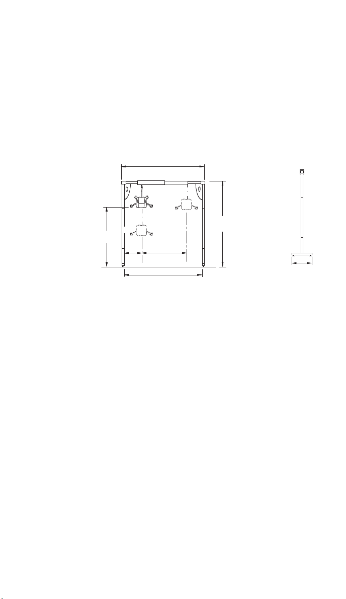
17
Lifting capacity 210 Kg (33 stone)(460 lb)
including hoist
Construction Legs - steel
Track - Aluminium
Cassette - Aluminium with ABS cover
Lifting Range Approximately 1525mm - 1825mm
Maximum loading per foot 100kg (16 stones) (220lb) (provided that the gantry is used in
accordance with the instructions in this user guide)
Assembled component weights:
Lower Leg section (x2) 7kg each (15.5lb)
Upper Leg section 8kg each (18lb)
Cassette (x1) 11kg (24lb)
End section/corner quadrant (x2) 5kg each (11lb)
Gas strut (x2) 1kg each (2.2lb)
Total weight of gantry 53kg (116lb)
CE MARK
The Chiltern Invadex Wispa LiteTrack Gantry carries the CE mark and complies with EC Directives:
Medical Device Directive(93/42/EEC)
Further assistance
Please telephone any Chiltern Invadex Office for further assistance.
Remember that service calls made after the guarantee period will be
chargeable. If the maintenance of the equipment is the responsibility of a
third party, for example the Social Services, please contact them in the first
instance.
Gantry Specification
2165 - 2465
(50mm intervals)
1010 - 1530440
Gantry at highest position 1825
Gantry at lowest position 1525
2040 - 2560
1890 - 2410 (Internal)
1100

User Guide
3
•
Always ensure the gantry track is directly above
the clients centre of gravity. Hoists should only be
used to lift vertically. Lifting at an angle will wear
the lifting tape prematurely and affect the stability
of the gantry.
•
Always ensure the top beam is horizontal and the
leg adjustment pin is located in the same position
on each side.
•
All fixings should be checked on a regular basis.
•
The cassette case and mechanical parts should
only be removed by a qualified service engineer,
trained by Chiltern Invadex.
•
Do not touch any of the moving parts in the hoist
unit or in the track. Call Chiltern Invadex for assistance.
•
Always ensure the legs are positioned as shown
in Fig 13 of this user guide
•
Take care when moving around the gantry to avoid
trip hazards such as the legs, handwheels and
potential injury from the corner quadrant.
•
Take care when attaching or removing a sling as a
swinging carry bar or hoist could cause injury.
•
For maximum comfort always move the user in one
movement and avoid stop/starting the hoist.
Some occupants are reassured if the carer holds
them whilst the hoist is traversing across the track.
•
Never leave a client unattended on the gantry.
•
Keep this user guide readily available for other users.
•
Always ensure there is sufficient clearance width
and height to erect/dismantle the gantry.
•
If the gantry is to be dismantled always remove the
Wispa Lite portable hoist from the gantry before
attempting to dismantle the gantry. The hoist should
be lowered onto a bed, chair or a Chiltern Invadex
transportation trolley before it is disconnected from
the gantry track.
•
Always follow the assembly/dissassembly
instructions contained in this guide.
After use
Chiltern Invadex LiteTrack Portable Gantry
18
Warranty
Your Chiltern Invadex Wispa LiteTrack Gantry carries a 2 year warranty
from the date of purchase, subject to the following :-
1. Should you experience any problems with our workmanship
or materials within the first 2 year period please contact
your point of purchase.
2. Repairs made during the warranty period will be carried out
free of charge, provided the product has been used strictly
in accordance with the guidelines set out in this user guide.
3. Our warranty does not cover replacements, adjustments or
repairs which may be required as a result of normal wear
and tear, wilful or accidental damage, misuse, neglect or
any other cause which is beyond the control of
Chiltern Invadex.
4. Modifications and repairs made to this product by
unauthorised persons will render the warranty void.
5. Only parts manufactured or approved by Chiltern Invadex
shall be used to repair this product. Use of unauthorised parts
will invalidate all warranties and remove all liability from
Chiltern Invadex for the safety of this product.
6. Chiltern Invadex shall in no event be liable for any damages,
costs or expenses arising from any claim made under this
warranty (save for any legal liability of Chiltern Invadex for
death or personal injury resulting from the company’s
negligence in respect of its products).
7. This warranty does not affect your statutory consumer rights.

Chiltern Invadex LiteTrack Portable Gantry
2
•
Only a single hoist should be attached to the gantry at
any one time
•
Do not operate the WispaLite Portable Hoist and gantry
without training in the safe operation of the hoist,
gantry and slings. The gantry should only be assembled
by a competent person.
•
Only use slings which have been assessed as
suitable by a competent person.
•
Read the Wispa Lite Portable hoist User Guide in
conjunction with this guide.
•
Read the relevant Sling User Guide, which is
provided with each sling. It explains in detail how to
use slings correctly.
•
Do not use the Gantry if there is any doubt about the
integrity of the gantry, wear to the hoist carry bar or
there is fraying or stitch damage to the lifting tape or
slings, or if the gantry or hoist itself is damaged in any way.
•
Do not exceed the Maximum load of the gantry or hoist.
Wispa LiteTrack Gantry 210kgs (33 Stone) (460 lb)
WispaLite Portable Hoist 200kgs (31 Stone) (440 lb)
•
Ensure when the gantry and hoist are in use that
the surrounding area is clear and the person being
lifted is clear of all objects.
•
Always ensure the gantry is assembled and
adjusted for level using the spirit levels on the end beams.
•
There are only 3 width adjustment holes per end
beam. The pin must always be located in one of these.
Safety
Safety Considerations
Intended Use of the Product
The Wispa LiteTrack gantry sytem has been designed to lift and transfer
aless able person with the help of a carer. The gantry is portable and
can easily be relocated and reassembled wherever required. It should be
used with the WispaLite Portable Hoist and a Wispa sling or other lifting
accessories from the Chiltern Invadex range, as assessed by a trained person.
Note: Not all slings and accessories are compatible with the Wispa Lite hoist.
If you are unsure please contact your nearest Chiltern Invadex Office.
The correct and appropriate use of this product will reduce the risks
associated with manual patient handling. The lifting/transferring task should
be assessed and planned by a trained person.
User Guide
19
Gantry Service Record
Serviced By
(company) .......................................................................................
Telephone no....................................................................................
Engineers training cert. no. Signature
................................................................ .................................
Date: .............................. Load Tested To: .............................Kgs
Comments..........................................................................................
...........................................................................................................
Serviced By
(company) .......................................................................................
Telephone no.......................................................................................
Engineers training cert. no. Signature
...................................................................... .................................
Date: .............................. Load Tested To: ..........................Kgs
Comments .........................................................................................
...........................................................................................................
Serviced By
(company) .......................................................................................
Telephone no.......................................................................................
Engineers training cert. no. Signature
...................................................................... .................................
Date: .............................. Load Tested To: ..........................Kgs
Comments .........................................................................................
...........................................................................................................
This manual suits for next models
1
Table of contents
Other Chiltern Invadex Medical Equipment manuals


