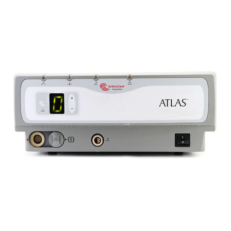
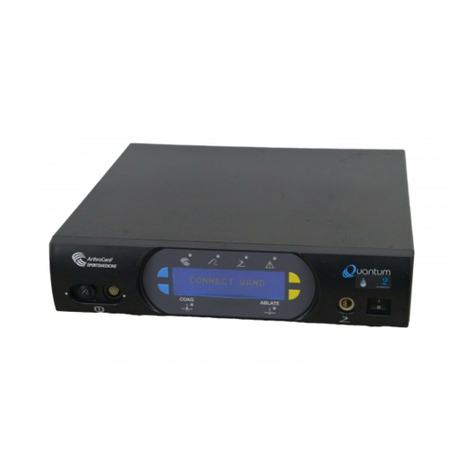
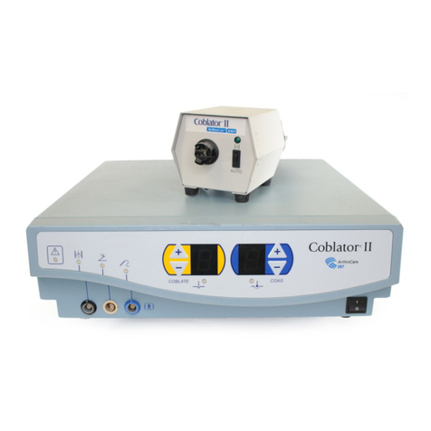
ArthroCare Quantum RF 12000 User manual

1
ArthroCare®Quantum™ (RF 12000) System
Service Manual
This equipment has been tested and found to comply with the limits for medical devices to IEC/EN 60601-1-2:2001.
These limits are designed to provide reasonable protection against harmful interference in a typical medical installation.
This equipment generates, uses, and can radiate radiofrequency energy and, if not installed and used in accordance
with the instructions, may cause harmful interference to other devices in the vicinity. If this equipment does cause
harmful interference to other devices, which can be verified by turning the equipment off and on, the user is encouraged
to try to correct the interference by one or more of the following measures:
• Reorient or relocate the receiving device,
• Increase the separation between the affected equipment and the Controller,
• Connect the affected equipment to an outlet or circuit different from that to which the Controller is connected, or
• Consult the manufacturer or field service technician for help.
High frequency surgical unit with respect to electrical shock, fire and mechanical hazards only in accordance with:
IEC/EN 60601-1/CAN/CSAC22.2 No. 601.1, and IEC/EN 60601-2-2.

2ArthroCare®Quantum™ (RF 12000) System
Service Manual

3
ArthroCare®Quantum™ (RF 12000) System
Service Manual
TABLE OF CONTENTS
Introduction ...............................................................................5
Functional Description of the Quantum System . . . . . . . . . . . . . . . . . . . . . . . . . . . . . . . . . . . . . . . . . . . . . . . . . . . . . .7
Board Level Description ......................................................................9
Main Board . . . . . . . . . . . . . . . . . . . . . . . . . . . . . . . . . . . . . . . . . . . . . . . . . . . . . . . . . . . . . . . . . . . . . . . . . . . . . . . . .10
Display Board with LCD Display . . . . . . . . . . . . . . . . . . . . . . . . . . . . . . . . . . . . . . . . . . . . . . . . . . . . . . . . . . . . . . . . .11
Medical Grade Power Supply . . . . . . . . . . . . . . . . . . . . . . . . . . . . . . . . . . . . . . . . . . . . . . . . . . . . . . . . . . . . . . . . . . .11
Front Panel Overlay . . . . . . . . . . . . . . . . . . . . . . . . . . . . . . . . . . . . . . . . . . . . . . . . . . . . . . . . . . . . . . . . . . . . . . . . . .11
Block Diagram for Quantum Controller .........................................................13
Inside view of the Quantum Controller .........................................................15
System Maintenance and Troubleshooting Guide .................................................16
Maintenance . . . . . . . . . . . . . . . . . . . . . . . . . . . . . . . . . . . . . . . . . . . . . . . . . . . . . . . . . . . . . . . . . . . . . . . . . . . . . . . .16
Troubleshooting Guide . . . . . . . . . . . . . . . . . . . . . . . . . . . . . . . . . . . . . . . . . . . . . . . . . . . . . . . . . . . . . . . . . . . . . . . .16
Technical Specifications .....................................................................19
Controller Functional Specifications . . . . . . . . . . . . . . . . . . . . . . . . . . . . . . . . . . . . . . . . . . . . . . . . . . . . . . . . . . . . . .19
Environmental . . . . . . . . . . . . . . . . . . . . . . . . . . . . . . . . . . . . . . . . . . . . . . . . . . . . . . . . . . . . . . . . . . . . . . . . . . . . . .19
Dimensions and Weight . . . . . . . . . . . . . . . . . . . . . . . . . . . . . . . . . . . . . . . . . . . . . . . . . . . . . . . . . . . . . . . . . . . . . . .19
Controller Measuring Function . . . . . . . . . . . . . . . . . . . . . . . . . . . . . . . . . . . . . . . . . . . . . . . . . . . . . . . . . . . . . . . . . .19
Safety . . . . . . . . . . . . . . . . . . . . . . . . . . . . . . . . . . . . . . . . . . . . . . . . . . . . . . . . . . . . . . . . . . . . . . . . . . . . . . . . . . . .19
Warnings, Precautions, and Adverse Events .....................................................20
Warnings . . . . . . . . . . . . . . . . . . . . . . . . . . . . . . . . . . . . . . . . . . . . . . . . . . . . . . . . . . . . . . . . . . . . . . . . . . . . . . . . . .20
Precautions . . . . . . . . . . . . . . . . . . . . . . . . . . . . . . . . . . . . . . . . . . . . . . . . . . . . . . . . . . . . . . . . . . . . . . . . . . . . . . . .20
Adverse Events . . . . . . . . . . . . . . . . . . . . . . . . . . . . . . . . . . . . . . . . . . . . . . . . . . . . . . . . . . . . . . . . . . . . . . . . . . . . .21
Output Test Procedures ......................................................................22
Output Test for the ArthoCare Quantum Controller . . . . . . . . . . . . . . . . . . . . . . . . . . . . . . . . . . . . . . . . . . . . . . . . . .22
Output voltage for Quantum Controller in Ablation and Coagulation Modes . . . . . . . . . . . . . . . . . . . . . . . . . . . . . . .23
Output Test Using an ElectrosurgicalAnalyzer . . . . . . . . . . . . . . . . . . . . . . . . . . . . . . . . . . . . . . . . . . . . . . . . . . . . .23
Power Output for Quantum System in Ablation and Coagulation Modes . . . . . . . . . . . . . . . . . . . . . . . . . . . . . . . . . .24
Customer Service ...........................................................................25
Warranty Information . . . . . . . . . . . . . . . . . . . . . . . . . . . . . . . . . . . . . . . . . . . . . . . . . . . . . . . . . . . . . . . . . . . . . . . . .25
Product Complaints . . . . . . . . . . . . . . . . . . . . . . . . . . . . . . . . . . . . . . . . . . . . . . . . . . . . . . . . . . . . . . . . . . . . . . . . . .25
Symbols Key ...............................................................................26

4ArthroCare®Quantum™ (RF 12000) System
Service Manual

5
ArthroCare®Quantum™ (RF 12000) System
Service Manual
Introduction
TheArthroCare®Quantum™ (RF 12000) System is a bipolar, radiofrequency (RF) electrosurgical system designed for
use in arthroscopic and orthopedic procedures. The System consists of the following components:
1) a bipolar radiofrequency Controller;
2) a reusable, non-sterile Power Cord;
3) a reusable, non-sterile Foot Control;
3a) a reusable, non-sterile wireless Foot Control (optional);
4) a reusable, non-sterile Patient Cable (optional); and
5) a disposable, sterileArthroWand®.
The Quantum (RF 12000) Controller consists of four main components: the Main Board, Display Board with LCD
Display, Medical Grade Power Supply and Front Panel Overlay. This manual will cover each of these components as
well as provide the necessary information on calibrating, troubleshooting and performing routine maintenance for the
Controller. Observe all warnings and precautions noted in this manual as well as in the Quantum (RF 12000) System
User’s Manual. Failure to do so may result in complications with the equipment, or safety hazards to the user or
patient.
WARNING: All service must be performed by an Authorized Repair Facility. All service or repair questions should be
directed to theArthoCare Customer Service Department.

6ArthroCare®Quantum™ (RF 12000) System
Service Manual

7
ArthroCare®Quantum™ (RF 12000) System
Service Manual
Functional Description of the Quantum System
The Quantum (RF 12000) Controller is designed to deliver RF energy to the electrode elements located at the distal end
of the sterile single-useArthroWands. Current flows from the active wand element to the integrated return Wand element,
providing a localized energy field. The result of this arrangement is controlled energy delivery with minimal collateral
tissue damage.
In the ablation mode, when sufficient energy is applied, the conductive solution is converted into a vapor layer (plasma)
containing energized charged particles. When the high-energy charged particles come in contact with tissue, they
cause its disintegration through molecular dissociation. This mode of operation results in relatively low treatment site
temperatures when compared to conventional electrosurgical and monopolar RF systems, thus yielding limited
collateral thermal damage to the surrounding untreated tissue.
The system can also function when a lower voltage is applied between the active and return electrode(s). In this case,
the electrical field is below the threshold required to create a plasma layer and resistive tissue heating occurs. This
mode is useful when a greater thermal effect is needed, i.e. for coagulation of blood vessel. The appropriate voltage
setting will depend on the design of Wand used, tissue type, and desired tissue effect.
The Quantum (RF 12000) System provides two output connectors:
• The Cable Receptacle with the tan ring will accept the reusable Patient Cable (27 pin) with a disposable
sterile Wand, making it compatible with the ArthroCare System 2000, or Integrated Cable Wand (ICW) with
gray mating end.
• The Cable Receptacle with the black ring delivers higher power and will accept ICW with black mating end.
Asingle digit LED output display on the front panel of the Controller indicates the ablation voltage level settings. The
table below shows relations between the open circuit output voltage and LED display in ablation and coagulation modes.
In coagulation mode, the LED display shows “C”. The Quantum (RF 12000) Controller has a fixed coagulation voltage.
Display Output voltage at tan receptacle Output voltage at black receptacle
(Vrms ± 10%) (Vrms ±10%)
0 0 0
1100 100
2 126 126
3 154 154
4 180 180
5 207 207
6234 234
7260 260
8 287 287
9 314 314
10 NA 320
Coag 0 0 0
Coag 1 65 65
Coag 2 100 100

8ArthroCare®Quantum™ (RF 12000) System
Service Manual

9
ArthroCare®Quantum™ (RF 12000) System
Service Manual
Board Level Description
The Quantum (RF 12000) Controller consists of four main components: Main Board, Display Board with LCD Display,
Medical Grade Power Supply and the Front Panel Overlay. This section will describe in detail the function of each of
these components.
Main Board:
• Provides primary power supply and patient isolation
• Generates a regulated power output of 70-330 Vrms (± 10%) at 100khz.
• Supports the system microcontroller (MCU) that sets the system clock, controls the peripheral components (Front
Panel Overlay, Display, Sound, Foot Control, etc.), identifies high power mode and sets the default and maximum
value for the type of Wand that is connected.
• Over temperature sensing circuitry
• Safety alarm circuitry
Display Board with LCD Display:
• Provides interface to the LCD Display.
• Provides LED indicators for Foot Control pedal, Wand, coagulation and alarm.
• Provides interface to Front Panel Overlay
Medical Grade Power Supply:
• Generates a regulated 12 VDC power output to supply the control circuitry
Front Panel Overlay:
• Houses the Up and Down arrow keys as well as the ablation indicator (Coblation Logo).

Main Board
The Main Board produces the 70-320 Vrms (±10%) at 100kHz signal that drives the electrodes at the distal end of the
ArthroWands. The nominal Raw + 320 VDC is generated from the 120 VAC or 240 VAC line voltages using automatic line
voltage switching (AVS) circuit built around U26. The circuit functions in two ways based on theAC input voltage. For
85 to 149 VAC, the circuit functions as a doubler. At 180 to 249 VAC, the circuit performs as a full-wave bridge rectifier.
The patient isolation barrier is created with the following components:
• T1, T2, T3, T4 and T5 current sensing transformers monitor current flowing through the four electrodes and
integrated return respectively.
• U1 and U5 digital isolators provide isolation and interface to the Wand via the Handpiece & Cable Unit. These
isolators along with theAD converter, U7 determine what type of Wand is connected, the position of the RF control
switches and send this information to the MCU via the SPI interface.
• U3 temperature monitor measures the temperature of TC enabled Wands and sends this information to the
MCU with the SPI interface.
• U13 digital isolator isolation to the RS-232 communication port.
•TheAD converter, U7 determines if the high power ICW is connected to the Controller.
• U12 and U4 provide the isolated +12 V to the RS-232 and Wand recognition circuits.
The nominal Raw + VDC drives a phase-modulated full-bridge switch-mode regulator which is used to provide the
necessary voltage output to the Wands. This circuit consists of four MOSFETs (Q14, Q15, Q16, and Q17) configured
as a full bridge. Their phase of conduction or overlay is controlled by a phase shift resonant controller (U27). The MCU
controls the on/off switching of this circuit by enabling the DC_EN which activates the “over current shutdown” (CS) on
U27 via Q12. The output from this full bridge switch mode regulator (+MOD) is applied to the 100kHz inverter circuitry
consisting of Q7, Q8, Q9, and Q10. The output from this inverter circuitry drives the output board via T6.
MCU - The MCU provides all necessary clock frequencies used throughout the system including the 100kHz sync
signal. The MCU is also responsible for the control of the LCD display and indicator lights on the Display Board, the
Up/Down arrow keys on the Front Panel Overlay, and the interface for the Foot Control. The MCU controls the different
safety monitoring circuits in the system. This includes the output current limit circuit, over temperature sensing circuit,
and detection of the Wand or Foot Control circuit. Avariety of different audio tones are associated with these safety-
monitoring circuits as well as with the normal operations of the system.
10 ArthroCare®Quantum™ (RF 12000) System
Service Manual

11
ArthroCare®Quantum™ (RF 12000) System
Service Manual
The following table describes each type of audio tone in detail. It includes the type of tone, description, and frequency
of the tone.
Type Description Frequency
Ablation tone Tone for normal operation Continuous tone @ 620Hz
Set Point tone Tone when setting voltage level Single tone, 200ms @ 620Hz
Alarm tone Tone for current limit Alternating tone 200ms
@ 620Hz and 1240Hz
Interlock tone Tone when Foot Control pedal Intermittent tone 200ms
is pressed and either Wand or @2480 Hz
Patient Cable is not connected
Coagulation tone Tone when in Coagulation mode Continuous tone @ 1240Hz
Medical Grade Power Supply
The Medical Grade Power Supply is an off-the-shelf SMPS that converts the 100-240 VAC supply voltage to a
regulated 12 VDC output that is used to power the system control circuitry.
Display Board
The Display Board supports the LCD display and the indicator lights for the Foot Control, Wand, ablation, coagulation,
and alarm. U1 is the port expander that provides the interface for Up and Down keys as well as the driving capability for
the indicator lights for the Foot Control, Wand, ablation (Coblation Swirl Logo), coagulation and alarm. U5 provides the
control voltages required to activate the LCD display.
Front Panel Overlay
The Front Panel Overlay is a membrane panel that contains Up and Down arrow keys as well as the indicator lights.

12 ArthroCare®Quantum™ (RF 12000) System
Service Manual

13
ArthroCare®Quantum™ (RF 12000) System
Service Manual
Block Diagram for Quantum (RF12000) Controller
MCU and Control
Logic
Control
Signals
4kV Isolation
DIG ISO
12/12 VDC
Converter
12 VDC
RS-232
SPI
Vmod (20-70VDC)
RF Output Stage - 4 kV Isolation
Main Board
Bipolar Supply
Bipolar Return
Patient Contacting Parts
5 VDC ISO
SETPOINT
COAG
CUT
TC
PROBE ID1
PROBE ID2
Temperature/Probe ID Sense -
4 k V Isolation
I
2C AND 5 VDC Supply
Power Entry
Module
Power Switch
120/240 VAC
50/60 Hz
Rectifier and
DC-DC SMPS
DC Power Supply
RF Isolation
Transformer
and Relays
AD Converter
12/12 VDC
Converter
Digital Isolators
Display Boardand LCD

14 ArthroCare®Quantum™ (RF 12000) System
Service Manual

15
ArthroCare®Quantum™ (RF 12000) System
Service Manual
Inside view of the Quantum (RF 12000) Controller
Front View
Back View
COOLING FAN MEDICAL GRADE
POWER SUPPLY
POWER INLET
MODULE
MAIN BOARD
SPEAKER
FRONT PANEL
OVERLAY
VOLUMEADJUST
KNOB
EQUIPOTENTIAL LUG
POWER SWITCH
FOOTSWITCH
CONNECTOR
DISPLAY BOARD WITH
LCD DISPLAY 18 PIN CONNECTOR
27 PIN CONNECTOR

System Maintenance and Troubleshooting Guide
Maintenance
The Quantum (RF 12000) Controller has been designed to function with minimal periodic maintenance, inspection, or
internal system calibration. Cleaning of the outside surfaces of the Quantum (RF 12000) Controller is recommended in
accordance with standard hospital practice. Periodic cleaning of the outside surfaces may be accomplished by using a
nonabrasive cleaning detergent. Also, periodic cleaning and inspection of the Power Cord should be performed.
Troubleshooting Guide
This section is designed to aid the trained service technician/engineer in troubleshooting the Quantum
(RF 12000) Controller. This section is only designed to troubleshoot to board level.
WARNING: Only trained qualified technicians should perform any repairs on the Quantum (RF 12000) System.
Please contact theArthroCare Corporation Customer Service Department before attempting any repairs on
the Quantum (RF 12000) System.
Error Symptom Corrective Action
Controller does not power up after the 1. Power Cord – Check that the Power
power switch is pressed. Cord is plugged in properly to the Controller and into the
appropriate outlet. If necessary, replace the Power Cord.
2. In-line fuses – Check that the in-line fuses, located in
the rear of the instrument, are not blown. If they are
blown, replace with the appropriate value fuse as per the
User’s Manual.
3. Main Board – Possible defective Main Board. Replace
Main Board.
Green wand LED does not illuminate 1. Patient Cable – Check that the Patient Cable is
when a Wand with the Patient Cable connected correctly.
or ICW is connected to the UUT. 2. Wand – Possible Wand failure. Change Wand.
3. Patient Cable – Possible defective Patient Cable.
Replace Patient Cable.
4. LED – Possible defective LED. Replace Overlay.
16 ArthroCare®Quantum™ (RF 12000) System
Service Manual

17
ArthroCare®Quantum™ (RF 12000) System
Service Manual
Troubleshooting Guide Cont’d
Error Symptom Corrective Action
Green Foot Control 1. Foot Control Connector – Check that the
LED does not illuminate. Foot Control is properly connected
to the Controller.
2. Foot Control – Possible defective Foot
Control. Replace Foot Control.
3. LED – Possible defective LED. Replace
Overlay.
No Output 1. Foot Control and/or Patient Cable – Check all
connections for the Foot Control, Patient
Cable and Wand.
2. Wand – Possible Wand failure. Replace Wand.
3. Patient Cable – Possible Patient Cable failure.
Replace Patient Cable.
4. Internal Harness Cable – Check that the
main harness cable from the Output Board to
the front panel Patient Cable connector is
connected properly.
5. Main Board – Possible Main Board failure.
Replace Main Board.
6. Voltage level set at zero – Make sure that the
voltage level is set at a number ≥ 1.
Intermittent monotone alarm and the red 1. Connections – Check all connections to the
LED illuminates when Wand is activated instrument. Make sure that the activated Wand
with the Patient Cable or ICW are seated
properly.
2. Wand – Possible Wand failure. Replace Wand.
3. Main Board – Possible Main Board failure.
Replace
Main Board.

Troubleshooting Guide Cont’d
Error Symptom Corrective Action
Dual tone alarm and the red LED illuminates 1. Safety feature - The warning light of
when Wand is activated. the Quantum (RF 12000) Controller is illuminated when
the Wand is activated. The Quantum (RF 12000)
Controller is designed to signal this type of alarm when
the Wand is activated for an extended period of time
without touching tissue. If this occurs, release Foot
Control to reset the unit.
2. Wand – Possible Wand failure. Replace Wand.
3. Patient Cable – Possible Patient Cable failure. Replace
Patient Cable.
Flashing display and indicator lights. 1. Main Board – Main Board failure. Replace Main Board.
18 ArthroCare®Quantum™ (RF 12000) System
Service Manual

19
ArthroCare®Quantum™ (RF 12000) System
Service Manual
Technical Specifications
Controller Functional Specifications
Input Voltage . . . . . . . . . . . . . . . . . . . . . . . . . . . . . . . . . . . . . . . . . . . . . . . . . . . . . . . . . . . . . . . . . . . .100-120/220-240 V~
Input Frequency . . . . . . . . . . . . . . . . . . . . . . . . . . . . . . . . . . . . . . . . . . . . . . . . . . . . . . . . . . . . . . . . . . . . . . . . . . . .50/60Hz
RMS Current . . . . . . . . . . . . . . . . . . . . . . . . . . . . . . . . . . . . . . . . . . . . . . . . . . . . . . . . . . . . . . . . . . . . . . . . . . . . . . .8 / 4 A
Maximum Output Power . . . . . . . . . . . . . . . . . . . . . . . . . . . . . . . . . . . . . . . . . . . . . . . . . . . . . . . . . . . . . . .400W @ 217 Ω
Output Frequency . . . . . . . . . . . . . . . . . . . . . . . . . . . . . . . . . . . . . . . . . . . . . . . . . . . . . . . . . . . . . . . . . . . . . . . . . . .100kHz
Output Voltage Range . . . . . . . . . . . . . . . . . . . . . . . . . . . . . . . . . . . . . . . . . . . . . . . . . . . . .0-320 Vrms @ 100kHz +/-10%
Environmental
Operating temperature range . . . . . . . . . . . . . . . . . . . . . . . . . . . . . . . . . . . . . . . . . . . . . . . . . . . . . . . . . . . .10 °C to 40 °C
Storage/Transportation temperature range . . . . . . . . . . . . . . . . . . . . . . . . . . . . . . . . . . . . . . . . . . . . . . . . .-40 °C to 70 °C
Humidity range . . . . . . . . . . . . . . . . . . . . . . . . . . . . . . . . . . . . . . . . . . . . . . . . . . . . . . . . . . .10% to 85% non-condensing
Pressure range . . . . . . . . . . . . . . . . . . . . . . . . . . . . . . . . . . . . . . . . . . . . . . . . . . . . . . . . . . . . . . . . . . . . . .500 to 1060 kPa
Dimensions and Weight
Controller:
Weight (max) . . . . . . . . . . . . . . . . . . . . . . . . . . . . . . . . . . . . . . . . . . . . . . . . . . . . . . . . . . . . . . . . . . . . . . .< 5 kg (< 11 lbs)
Height . . . . . . . . . . . . . . . . . . . . . . . . . . . . . . . . . . . . . . . . . . . . . . . . . . . . . . . . . . . . . . . . . . . . . . . . . .10.2 cm (4.0 inches)
Width . . . . . . . . . . . . . . . . . . . . . . . . . . . . . . . . . . . . . . . . . . . . . . . . . . . . . . . . . . . . . . . . . . . . . . . . .40.6 cm (16.0 inches)
Length . . . . . . . . . . . . . . . . . . . . . . . . . . . . . . . . . . . . . . . . . . . . . . . . . . . . . . . . . . . . . . . . . . . . . . . .40.9 cm (16.1 inches)
Controller Measuring Function
Temperature range . . . . . . . . . . . . . . . . . . . . . . . . . . . . . . . . . . . . . . . . . . . . . . . . . . . . . . . . . . . . . . . . . . . . . . .20 to 60°C
Temperature resolution . . . . . . . . . . . . . . . . . . . . . . . . . . . . . . . . . . . . . . . . . . . . . . . . . . . . . . . . . . . . . . . . . . . . . . . . . .1°C
Calibrated accuracy . . . . . . . . . . . . . . . . . . . . . . . . . . . . . . . . . . . . . . . . . . . . . . . . . . . . . . . . . . . . . . . . . . . . . . . . . . .±3°C
Safety
The Quantum (RF 12000) Controller meets the requirements of IEC/EN 60601-1, IEC/EN 60601-1-2,
IEC/EN 60601-1-4, IEC/EN 60601-2-2, and CSA22.2 No. 601.1.IEC/EN 60601-2-18.All units are tested to verify that
they meet these requirements. These standards include, but are not limited to the following:
• Class Type Class I, Type BF
•Leakage current, isolated patient connections ≤ 100 µAat 100-120/220-240 V~, 50/60 Hz
• Leakage current, non-patient applied parts ≤ 500 µAat 100-120/220-240 V~, 50/60 Hz
•Power cord resistance to chassis ≤100 mΩ

20 ArthroCare®Quantum™ (RF 12000) System
Service Manual
Warnings, Precautions, and Adverse Events
The following is a list of Warnings and Precautions that apply to the general operation of the Quantum (RF 12000)
System. For specific warnings and precautions, please refer to the Wand and the Patient Cable Instructions for Use.
Warnings
• The RF 12000 System is intended for use by healthcare professionals only. The RF 12000 System may cause radio
interference or may disrupt the operation of nearby equipment. It may be necessary to take mitigation measures, such as
reorienting or relocating the RF 12000 System or shielding the location.
•Failure to follow all applicable instructions may result in serious surgical consequences.
• Explosion Hazard: The following substances will contribute to increased fire and explosion hazards in the operating room:
flammable substances (such as alcohol-based skin prepping agents and tinctures), flammable anesthetics, naturally
occurring flammable gases which may accumulate in body cavities such as the bowel, oxygen enriched atmospheres, and
oxidizing agents such as nitrous oxide (N2O) atmospheres.
• Fire Hazard: DO NOT place active accessories near or in contact with flammable materials (such as gauze or surgical
drapes).
• Electrosurgical accessories, which are activated or hot from use, can cause a fire.
• Accessory tips may remain hot enough to cause burns after the electrosurgical current is deactivated.
•Inadvertent activation or movement of Wands outside the field of vision may result in injury to the patient.
• Localized burns to the patient or physician may result from electrosurgical current carried through other instruments and
conductive objects.
•Electrosurgical current may be generated in conductive objects by direct contact with the active Wand or by the active or
return wand being in close proximity to a conductive object.
•If excessive heating or physical forces cause damage to the Wand tip, foreign body fragments may result, possibly requiring
extended surgery for removal.
•DO NOT use the Quantum (RF 12000) System with non-conductive media (e.g. sterile water, dextrose, air, gas, glycine,
etc.). Use only conductive media such as normal saline or Ringer’slactate.
•Electric Shock Hazard: DO NOT connect wet accessories to the Controller.
• Controller failure could result in an unintended increase in output power.
Precautions
•Prior to initial use, ensure that all package inserts, warnings, precautions, and Instructions for Use are read and understood.
• Safe and effective electrosurgery is dependent not only on equipment design, but also, to a large extent, on
factors under the user’s control. Only persons having adequate training should perform procedures with the Quantum
(RF 12000) System.
•Consult medical literature relative to techniques, complications, and hazards prior to performance of any procedure.
• Evaluate patients for predisposing medical problems that may be aggravated by the stress of surgery.
•Athorough understanding of the principles and techniques involved in electrosurgical procedures is essential to avoid shock
and burn hazards to both patient and medical personnel and damage to the device and other medical instruments. Ensure
that insulation or Controller grounding is not compromised.
•When instruments and accessories from different manufacturers are employed together in a procedure, verify compatibility
prior to initiation of the procedure.
Other manuals for Quantum RF 12000
1
Table of contents
Other ArthroCare Medical Equipment manuals
Popular Medical Equipment manuals by other brands

Protocol
Protocol Propaq 242 Directions for use

InfoBionic
InfoBionic MoMe Kardia System Patient Quick Reference Guide

GE
GE Solar 7000 Service manual

Thayer Medical Corporation
Thayer Medical Corporation LiteAire Instructions for use

Patterson
Patterson EX-6 Operation manual

Otto Bock
Otto Bock 8S4N Series Instructions for use