CHINT Astronergy CHSM6610M User manual

1
Crystalline Silicon PV
Module Installation
Manual
Rev1.2,Released in August 2021.

2
Directory
1Introduction....................................................................................................................................................... 3
1.1 Purpose.................................................................................................................................................... 3
1.2 Limitation of Liability............................................................................................................................. 3
2Regulations and regulations............................................................................................................................. 3
3Safety measures................................................................................................................................................. 4
3.1 General safety measures.......................................................................................................................... 4
3.2 Operational safety measures.................................................................................................................... 5
4Handling and unpacking .................................................................................................................................. 7
4.1 Transport ................................................................................................................................................. 8
4.2 Unpack .................................................................................................................................................... 8
5Mechanical installation..................................................................................................................................... 9
5.1 Installation conditions ............................................................................................................................. 9
5.2 Installation angle selection.................................................................................................................... 10
5.3 Installation Method ............................................................................................................................... 10
6Electrical Installation...................................................................................................................................... 15
6.1 Electrical properties............................................................................................................................... 15
6.2 Electrical connection............................................................................................................................. 16
6.3 Grounded............................................................................................................................................... 18
7Maintenance..................................................................................................................................................... 19
7.1 Routine inspection................................................................................................................................. 19
Modified version and date...................................................................................................................................... 20
3
1Introduction
First of all, thank you very much for using
Chint Solar Technology Co., Ltd. (hereinafter
referred to as Chint Solar) production of
photovoltaic modules.
Please read all the instructions in this manual
carefully before installation, as well as electrical and
mechanical requirements.
The installation and operation of photovoltaic
modules requires professional skills that only
professionals can do. The installation process is strictly
observed with all safety precautions in this manual and
the manual is kept for further reference. At the same
time, the installer must inform the end customer (or
consumer) of the above accordingly.
1.1 Purpose
This manual provides detailed instructions and
important safety precautions for the installation,
electrical connection and maintenance of single-sided
crystalline silicon photovoltaic modules (hereinafter
referred to as photovoltaic modules) produced by
Chint Solar. Covers photovoltaic module models such
as Table 1.
Table 1 This manual applies to photovoltaic module types
CHSM6610M
CHSM6610M(BL)
CHSM6610M/HV
CHSM60M-HC
CHSM60M(BL)-H
C
CHSM6610P
CHSM6610P/HV
CHSM60P-HC
CHSM6612M
CHSM6612M/HV
CHSM72M-HC
CHSM60M/LV-HC
CHSM6612P
CHSM6612P/HV
CHSM72P-HC
CHSM72M/LV-H
C
CHSM54M-HC
CHSM54M(BL)-H
C
1.2 Limitation of Liability
Since the use of this manual and the installation,
operation, use and maintenance of photovoltaic
modules are beyond the control of Chint Solar, this
manual does not have any warranty meaning, whether
express or implied. Chint will not be responsible for
any form of injury, including, but not limited to,
damage, damage, loss of life or additional expenses
caused by incorrect installation, operation, use and
maintenance of photovoltaic modules and systems.
Chint Solar reserves the right to update this
manual without prior notice. If there are
inconsistencies in the descriptions between different
language versions of this manual, the Chinese version
will prevail.
2Regulations and regulations
The mechanical and electrical installation of
photovoltaic modules should be carried out in
accordance with applicable laws and regulations,
including electrical law, building law and electrical
connection requirements. These regulations vary
depending on the installation location, such as the roof

4
of the building, the surface of the water, etc., or may
vary depending on the installation system voltage, dc
usage, or AC. Please contact your local authority for
specific terms.
3Safety measures
Chint solar modules are designed to meet the
requirements of IEC 61215 and IEC 61730,
application class A.
Modules rated for use in this application class may
be used in system operating at greater than 50V DC
or 240W, where general contact access is
anticipated. Class C fire rating(IEC61730)and
Category 4 fire rating (UL61730) are available
!warn
All safety rules should be read and understood
before installing, wiring, etc. / maintaining
photovoltaic modules. When the photovoltaic module
is exposed to sunlight or other light sources, direct
current is generated. Direct contact with the live part
of the photovoltaic module, such as terminals, whether
or not a photovoltaic module is connected, can result
in loss of life.
3.1 General safety measures
Before installation, please contact the
relevant local authority to determine the
installation permit and installation inspection
requirements that meet the local
requirements. The installation process should
comply with the safety rules applicable to all
components in the system, including cables,
terminals, charging monitors, batteries,
inverters, etc.
If you install or operate photovoltaic
modules on a rainy day or in the morning
with dew, you need to take appropriate
protective measures to prevent water vapor
from penetrating into the connector.
Unauthorized personnel are prohibited from
approaching the installation area or
photovoltaic module storage area.
It is forbidden to install or use damaged
photovoltaic modules.
It is forbidden to repair photovoltaic
modules by yourself, including but not
limited to replacing any components of
photovoltaic modules (diodes, junction
boxes, connectors, etc.).
It is forbidden to plug in connectors of
different types and models.
It is forbidden for photovoltaic modules to
be used or exposed to the following
substances in an environment containing the
following substances: grease or organic ester
compounds (such as DOP, plasticizers),
aromatics, phenols, ketones, halogenated

5
substances, mineral oil, alkanes (Such as
gasoline, cleaning lubricants, electronic
resurrection agents), alcohol, certain drugs
(white flower oil, active oil, bone-setting
water, thinner), adhesive sheets that can
generate oxime gas and potting glue (only
for connectors) (Such as KE200,
CX-200/chemlok, etc.)), TBP (plasticizer),
detergent, etc., to avoid chemical damage
and affect the electrical safety performance
of photovoltaic modules.
It is forbidden to install photovoltaic
modules in windy weather.
It is forbidden to focus sunlight on
photovoltaic modules.
It is forbidden to use photovoltaic modules
in relevant places such as movable platforms
(except for tracking brackets).
It is forbidden to disassemble and move any
part of the photovoltaic module; if the
connector of the photovoltaic module is wet,
do not perform any actions to avoid the risk
of electric shock.
Do not connect or disconnect the
photovoltaic module when there is current or
external current from the photovoltaic
module.
The cover of the junction box should always
be kept closed.
Avoid partial shading of photovoltaic
modules for a long time. Otherwise, the
temperature of the shaded solar cells will
rise (hot spot effect), and in severe cases, the
photovoltaic modules may be burned, or
even a fire may occur.
For photovoltaic modules used in deserts or
windy and sandy areas, it is recommended to
use connector dust caps before installation,
or take other measures to prevent sand and
dust from entering the connectors, otherwise
it may cause insertion problems or electrical
safety hazards.
3.2 Operational safety measures
During transportation and storage, avoid
damage or fall of the packaging; ensure that
the packaging box is ventilated, rain-proof
and dry; after arriving at the installation site,
carefully open the outer packaging to
prevent scratches and bumps on the
photovoltaic modules due to improper
unpacking Such phenomena; when stacking
photovoltaic modules, the stacking
requirements must be strictly followed.
Avoid impact or scratches on any part of the
photovoltaic module, otherwise the
reliability and safety of the photovoltaic

6
module will be affected; standing or walking
on the photovoltaic module is prohibited; at
the same time, in order to avoid glass
damage, it is forbidden to apply excessive
load or Distorted photovoltaic modules.
Do not install or carry photovoltaic modules
by one person. It is forbidden to pick up,
drag, or move photovoltaic modules by
grabbing the junction box (including the box
body, cables, and connectors); when placing
a photovoltaic module on a flat surface, It
must be operated carefully and be aware of
bumps in the corners.
When installing or repairing the photovoltaic
system, do not wear any metal accessories to
avoid the risk of electric shock; if it is
installed far above the ground, please wear a
seat belt.
When operating photovoltaic modules in the
sun, please use insulated tools, and wear
rubber gloves and protective clothing. At the
same time, in order to avoid the risk of arc
and electric shock, do not directly touch the
junction box and the end of the output cable
(connector) with your hands.
When the photovoltaic modules are
electrically connected, choose a dry and
weak morning or evening; or use opaque
materials to completely cover the surface of
the photovoltaic modules to prevent current
generation.
A certain distance between the photovoltaic
module and the installation surface should be
kept to prevent the installation surface from
touching the junction box.
When installing on the roof, comply with the
fire protection requirements of the building.
It is recommended to install photovoltaic
modules on a fireproof and insulated roof
covering, and ensure adequate ventilation
between the photovoltaic modules and the
installation surface. In order to ensure the
fire rating on the roof, the minimum distance
between the frame of the photovoltaic
module and the roof surface is 10 cm.
The connector must be fully mated when
wiring. If the cable is too long, it is
recommended to fix the cable to the
installation system with a UV resistant nylon
cable tie. When fixing the cable to the
bracket, the bending radius of the cable
should not be less than 60mm.
Avoid directly exposing cables and
connectors to sunlight. Please use
anti-ultraviolet cables.
Do not disconnect the electrical connection

7
when there is a load.
It is strictly forbidden to try to disassemble
the photovoltaic module, and it is strictly
prohibited to remove the nameplate of the
photovoltaic module or other parts on the
photovoltaic module; it is strictly forbidden
to paint or apply any adhesive on the surface
of the photovoltaic module;
It is strictly forbidden to drill holes in the
frame of the photovoltaic module.
It is strictly forbidden to scratch the
anodized layer on the surface of the
aluminum alloy frame, except when it is
connected to the ground. Scratches may
cause corrosion of the frame, affecting the
frame's load-bearing capacity and long-term
reliability.
If the photovoltaic module glass or other
packaging materials are damaged, please
wear personal protective equipment to
separate the photovoltaic module from the
site or the circuit. It is strictly forbidden to
touch wet photovoltaic modules, unless you
are wearing electric shock protection
equipment that meets the requirements.
When professionals replace or repair
photovoltaic modules, do not damage the
surrounding photovoltaic modules or their
support structures.
When cleaning photovoltaic modules, you
must follow the cleaning requirements of
photovoltaic modules.
The connectors must be kept dry and clean
to ensure that they are in good working
condition. Do not insert other metal objects
into the connector or make electrical
connections in any other way.
4Handling and unpacking
If the photovoltaic module is not in use, please
do not open the product packaging. The goods should
be stored in a dark, dry and ventilated place. If the
photovoltaic modules are stored in an uncontrollable
environment, the storage time must be less than 3
months when the outer packaging of the photovoltaic
modules is kept intact.
It is recommended to take appropriate amount of
photovoltaic modules for unpacking according to the
project progress every day, and the unpacked
photovoltaic modules should be installed within a day.
After unpacking, the photovoltaic modules are stacked
on the ground. In severe weather such as heavy rain,
the photovoltaic modules may be immersed in water
for a long time and affect the reliability of the product.
In severe weather such as typhoons, photovoltaic
modules that have not been installed may also be
scraped away.

8
4.1 Transport
When the photovoltaic modules are transported
to the project site, they must be transported in the
packaging box provided by Chint Solar, and should be
stored in the original packaging box before installation.
Please protect the packaging from damage.
It is necessary to protect the safety of
photovoltaic modules when unloading, especially
when hoisting roof projects. It is forbidden to use
lifting straps directly on the pallet for hoisting. The
photovoltaic modules should be placed in a protective
device and then hoisted to the roof to prevent the
packing box from deforming and bumping against the
wall during the hoisting process.
!Special instructions
Due to the limitation of the height of the
container, when the photovoltaic modules are removed
from the container, the distance between the upper
surface of the forklift tines and the ground should be
less than 80mm, otherwise collisions may easily occur,
which may damage the photovoltaic modules.
4.2 Unpack
When unpacking, you need to tear the stretch
film first, then use a knife to cut the binding tape, and
remove the packing box cover.
If the inner packaging is fixed with anti-falling
tape, a group of two should hold the frame with both
hands in the same direction to take out the
photovoltaic module one piece/time, and remove the
photovoltaic module by tearing off a piece of fixing
glue. The photovoltaic modules in the box are dumped;
if the internal packaging is fixed by the internal
packing belt, first cut the internal packing belt, use
anti-inverted sticks and other non-sharp and reliable
items to hold one side of the long side frame, and then
cut the other side Two people move and take out the
photovoltaic modules one by one around the frame; the
whole handling process needs to be handled with care,
and must not collide with hard objects or any part of
the frame touches the ground and drags.
4.3 Stacking of photovoltaic modules
When taking out the photovoltaic module from
the packing box, you need to lay the cardboard on the
ground first to prevent the photovoltaic module from
colliding and scratching with the cement surface/hard
object on the ground, color steel tile, metal corrugated,
etc.
When the photovoltaic modules are stacked, they
must be neatly and stably stacked on a horizontal
surface, and stacked with the glass side facing down
and the back side facing up. At the same time, there
must be cardboard bedding under the photovoltaic
modules. For example, when installing photovoltaic
modules on the roof, the number of piles should not
exceed 20. For roofs with poor load-bearing capacity,

9
it is recommended that the designer or installer
evaluate the load-bearing capacity of the roof and
reduce the load-bearing unit area of the roof by
reducing the number of piles. At the same time, avoid
installation tools and other objects on the surface of
the photovoltaic module.
Chint PV modules adopt high and low current
bins, and the handlers need to place them separately
and mark them according to the markings on the
power list of the PV module outer packaging (for
example, 270W-L means low current gear; 270W-H
means high current Gear position; the current division
method required by other customers is similar);
According to the system design requirements, the same
current gear position is usually required in the same
array during installation.
If the customer requires PV modules to be
distinguished by color, the outer packaging box shall
be marked accordingly, and the PV modules shall be
marked to prevent confusion when they are taken out
of the packaging box and stacked. According to the
system design requirements, the color of photovoltaic
modules in the same row or square array should be the
same.
5Mechanical installation
5.1 Installation conditions
Recommended ambient temperature: -20°C to
+50°C; extreme working environment
temperature of photovoltaic modules: -40°C to
+85°C.
Photovoltaic module mechanical load: Under
standard installation conditions, the maximum
test snow/wind load is 5400Pa/2400Pa, and the
design load (considering a safety factor of 1.5) is
3600Pa/1600Pa. For specific installation methods
and mechanical load values of photovoltaic
modules, please refer to Table 2 for detailed
installation instructions for photovoltaic modules.
Photovoltaic modules are strictly prohibited to be
installed and used in excessive environments such
as hail, snow, hurricane, sandstorm, dust, air
pollution, and soot. It is strictly forbidden to
install or use photovoltaic modules in a closed
environment with strong corrosive substances
(such as salt, salt spray, salt water, active
chemical vapor, acid rain, strong steam, or any
other substances that will corrode photovoltaic
modules and affect the safety or performance of
photovoltaic modules. ) In the environment.
If photovoltaic modules will be installed in
special environments such as high temperature
and high humidity environment, wet salt fog
environment (C3 and above areas specified in
ISO 9223), water and breeding farms, etc., the
purchaser or user must inform Chint in advance.
The types of photovoltaic modules, BOM, and
10
quality assurance issues shall be decided by the
two parties through a joint re-agreement.
If the above precautions are not followed, the
Chint Solar Warranty will be invalid.
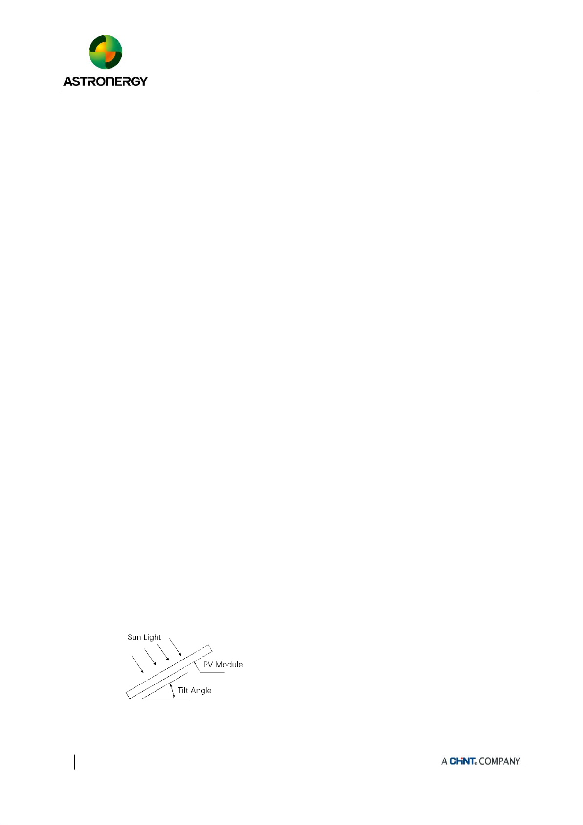
5.2 Installation angle selection
The tilt angle of the modules is measured between
the surface of modules and a horizontal
grounding face, as shown in figure 1. The
modules generate maximum power output when it
faces the sun directly.
In the northern hemisphere, modules should
typically face south, and in the southern
hemisphere, modules should typically face north.
Dust building up on the surface of the modules
can impair module performance, Chint Solar
recommends installing the modules with a tilt
angle of at least 10 degrees, making it easier for
dust to be washed off by rain. At the same time, it
is conducive to the flow of accumulated water on
the surface of the module, and avoids long-term
large amounts of accumulated water leaving
marks on the glass surface, thereby affecting the
appearance and performance of the module.
Figure a Schematic diagram of tilt angle
PV modules connected in series should be
installed in the same orientation and angle. If the
orientation and angle are different, the solar
radiation received by each module may be
different, resulting in power loss.
5.3 Installation Method
The photovoltaic module mounting bracket must
be made of durable, corrosion-resistant, and
UV-resistant materials. The mounting bracket
must be inspected and tested by a third-party
testing organization with static mechanical
analysis capabilities to meet the country, region,
or corresponding international standards.
The photovoltaic module must be firmly fixed on
the mounting bracket. If the photovoltaic module
is installed in a snow-covered area, the height of
the support should ensure that the lowest point of
the photovoltaic module will not be covered by
snow. In addition, it should be ensured that the
lowest point of the photovoltaic module will not
be blocked by surrounding trees or other plants.
When the photovoltaic module is installed on a
bracket parallel to the roof, the minimum gap
between the frame of the photovoltaic module
and the roof is 10cm, and air circulation is
required to prevent damage to the wiring of the
photovoltaic module.
The frame of the photovoltaic module will have
11
the effect of thermal expansion and contraction,
and the spacing between the two adjacent
photovoltaic module frames should not be less
than 10mm during installation.
For specific installation methods, please refer to
the following installation specifications.
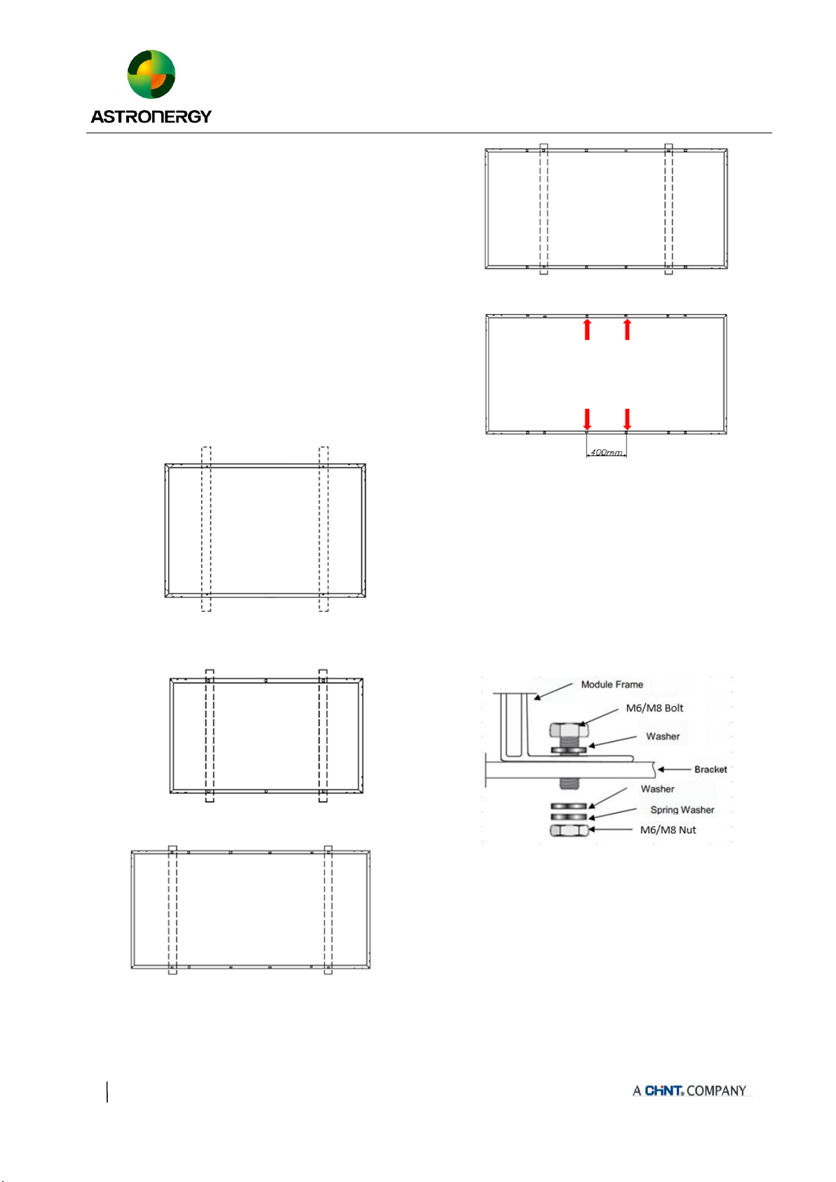
5.3.1 Bolting through the mounting holes
All modules must be securely fastened with at
least 4 bolts (As shown in Figure 2, Figure 3, Figure 4 ,
Figure 5 and Figure 6).
Fig 2 Bolt installation for 54cell
Fig 3 Bolt installation for 60cell
Fig 4 Outer four-hole bolt installation for 72cell
Fig 5 Internal four-hole bolt installation for 72cell
Fig 6 400mm pitch bolt installation for 72cell
!note :In order to achieve maximum safety
precautions against wind and snow loads, it is
recommended that all available mounting holes should
be used.Bolts are inserted as described in the process
below (Sketch figure 7).
Figure 7 Schematic diagram of bolt installation process
①Place the module on the supporting bars
underneath.
②Insert the four stainless-steel bolts (M6) through
the holes (7x11.5mm) or stainless-steel bolts (M8)
through the holes (9x14mm) in the frame
according to the Figure 2, Figure 3 & Figure 4.
The 400mm pitch mounting hole size is 7x10mm,

12
and 4 M6 stainless steel bolts are required (Figure
5).
③Secure each bolt to the frame with stainless-steel
washers, one for each side of the mounting
structure; and screw on either a stainless-steel
spring washer or a toothed lock washer. Finally,
secure with a stainless steel nut.
④The reference value of tightening torques should
be within 9~12Nm & 17~23 Nm respectively for
M6 & M8 bolts, depending on bolt class. For the
bolt grade, the technical guideline from the
fastener suppliers should be followed. For the
torque value, recommendations from specific
clamping hardware suppliers should prevail.
5.3.2 Clamping on the frame surface
Photovoltaic modules can be installed across the
support frame (Figure 8) or parallel to the frame of the
photovoltaic module (Figure 9). When using clamps to
install, each photovoltaic module must be fixed with at
least 4 clamps.
Figure 8 Rail vertical long frame installation
Figure 9 Installation of rails coincident with short frame
!note:
The length of supporting bars must be longer than
the length of module frame, otherwise please
confirm with our product team to get approval.
The above two diagrams show the installation
method using aluminum clamps (also called
fixtures). "D" indicates the allowable installation
range of the aluminum press block. Please refer to
4.3.3 for the specific recommended installation
location and corresponding load ("---" indicates
that the photovoltaic module does not apply to the
above installation methods).
Each aluminum pressure block is equipped with an
M8 bolt, a flat washer, a spring washer and an M8
nut. The fixing steps are as follows:
①Place the module on the two supporting bars (not
provided). The bars should be made with stainless
material and treated with an anti-corrosion process
(e.g., hot dipped galvanizing). Each PV module
needs at least four clamps to fix. Do not make the
clamp contact the glass directly or make the
aluminum frame deformation in the installation
process, and avoid the shadow of solar PV modules,
otherwise may break the modules.
②Be sure to avoid shadowing effects from the
module clamps. Weep holes on the module frame
must not be closed or obscured by the clamps. The
clamp must overlap the module frame by at least
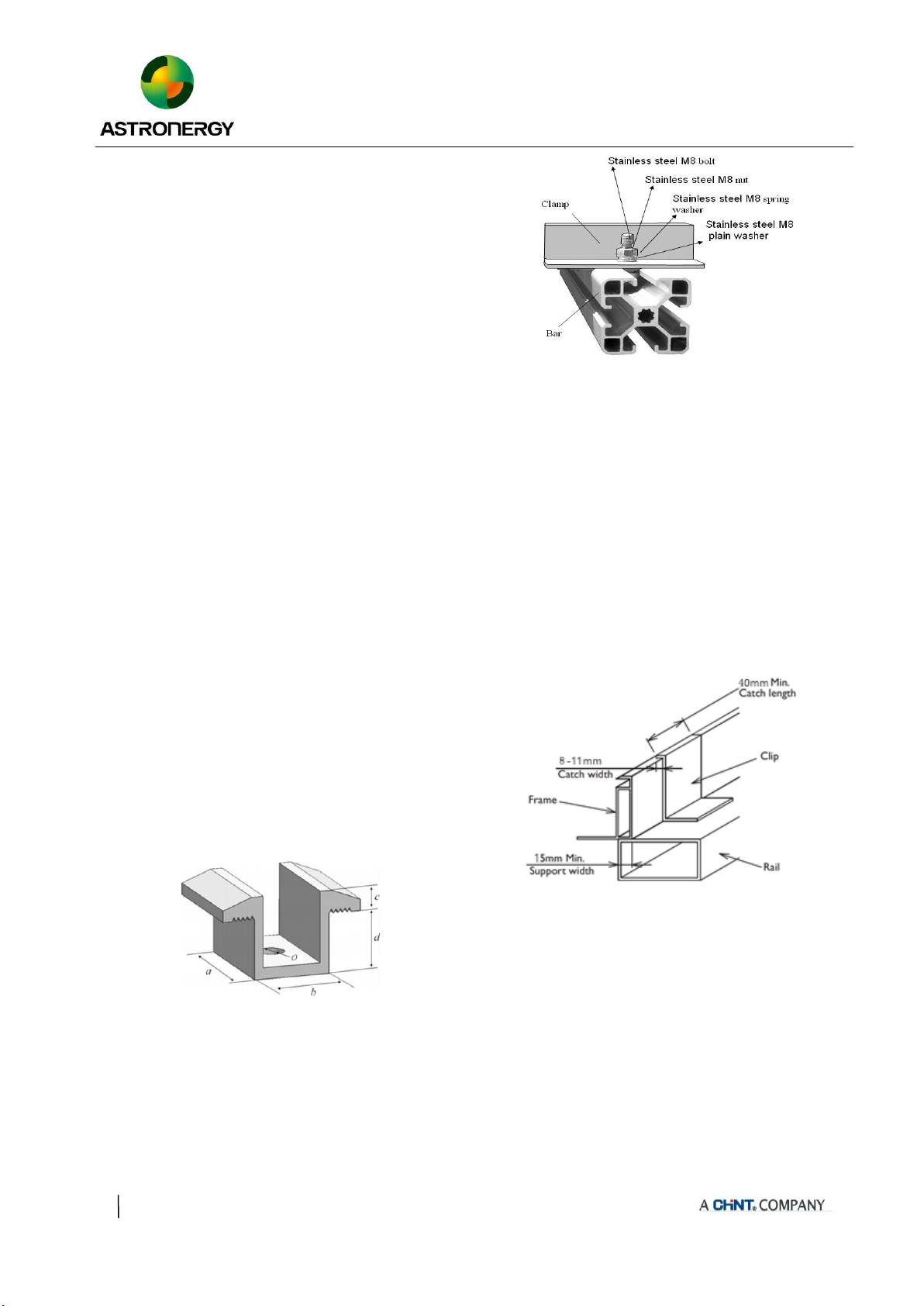
13
8mm but no more than 11mm (The clamp section
can be changed under the premise of ensuring the
reliable installation of the components).
③The bar’s top surface contacted with module frame
should come with grooves compatible with an M8
bolt.
④If the bars do not come with grooves, holes of a
suitable diameter may need to be drilled to allow
bolts to be attached to the bars at the same locations
as mentioned above.
⑤Secure each clamp by attaching plain washer,
spring washer, and nut, in that order.
⑥Both of close-ups of Figure 10, indicating the
middle clamps and Figure 11, indicating the side
clamps for reference. Suggest the dimensions for
middle clamps are: a≥40mm, b≥26mm, c≥5mm,
d≥28mm, and Ø=9mm. The torque for tightening
the nut and bolts are recommended 17~23Nm when
the property class of bolts and screws is Class 8.8.
Figure 10 Schematic diagram of intermediate pressing block
Figure 11 Schematic diagram of side pressing block
⑦For the installation method shown in Figure 9, the
modules need to be fixed with professional solar
pressure blocks (as shown in Figure 12), and the
overlap between the C surface of the module and
the guide rail should be ≥15mm. If improper
fixtures or incorrect installation methods are used,
the Chint Solar limited warranty will be invalid.
Figure 12 Requirements for mounting clamps when the guide
rails coincide with the long frame
14
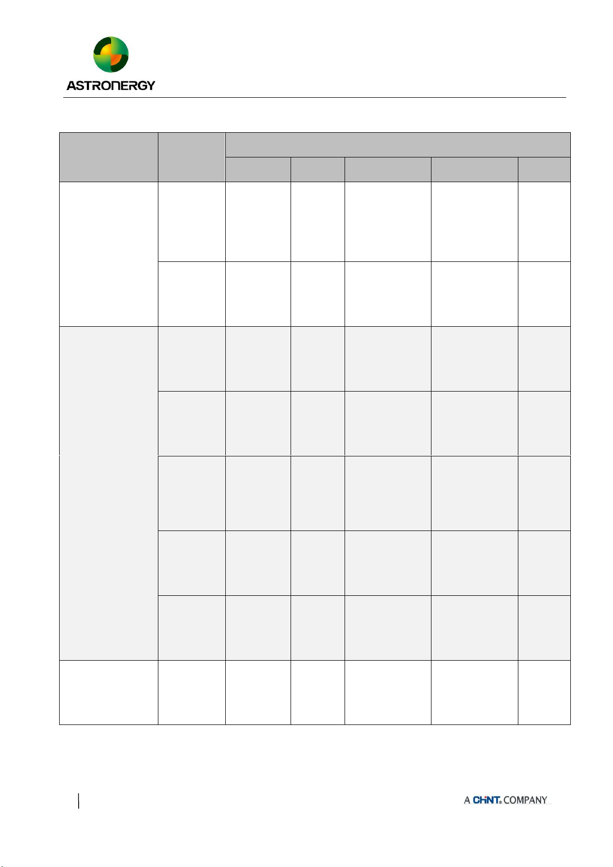
Table 2 Installation range and corresponding values
Module type
Dimensions
L*W*H (mm)
Installation method
Fig b & Fig C
Fig d
Fig g
Fig h
Fig e
CHSM6610M
CHSM6610M/HV
CHSM6610P
CHSM6610P/HV
CHSM6610M(BL)
1648*990*35
1648*990*40
+5400Pa
-2400Pa
---
+5400/-2400Pa
Installation scope
198~408mm
+2400/-2400Pa
Installation scope
50~200mm
---
1650*992*35
1650*992*40
+5400Pa
-2400Pa
---
+5400/-2400Pa
Installation scope
198~408mm
+2400/-2400Pa
Installation scope
50~200mm
---
CHSM60M-HC
CHSM60P-HC
CHSM60M(BL)-HC
CHSM60M/LV-HC
1666*992*35
+5400Pa
-2400Pa
---
+5400/-2400Pa
Installation scope
207~408mm
+2400/-2400Pa
Installation scope
50~200mm
---
1675*992*35
+5400Pa
-2400Pa
---
+5400/-2400Pa
Installation scope
215~415mm
+2400/-2400Pa
Installation scope
50~200mm
---
1692*1002*35
+5400Pa
-2400Pa
---
+5400/-2400Pa
Installation scope
350±50mm
+2400/-2400Pa
Installation scope
50~200mm
---
1755*1038*35
1765*1048*35
+5400Pa
-2400Pa
---
+5400/-2400Pa
Installation scope
400±50mm
+1800/-1800Pa
Installation scope
200±50mm
---
1755*1038*30
+5400Pa
-2400Pa
---
+5400/-2400Pa
Installation scope
350±50mm
+1800/-1800Pa
Installation scope
200±50mm
---
CHSM54M-HC
CHSM54M(BL)-HC
1708*1133*30
+5400Pa
-2400Pa
---
+5400/-2400Pa
Installation scope
359±50mm
+1400/-1400Pa
Installation scope
200±50mm
---

15
Table 2 (continue)
Module type
Dimensions
L*W*H (mm)
Installation method
Fig b & Fig C
Fig d
Fig g
Fig h
Fig e
CHSM6612M
CHSM6612M/HV
CHSM6612P
CHSM6612P/HV
1954*990*40
1954*990*35
+5400Pa
-2400Pa
+5400Pa
-2400Pa
+5400/-2400Pa
Installation scope
299~498mm
---
+2400Pa
-2400Pa
+Bumper
1960*992*40
1960*992*35
+5400Pa
-2400Pa
+5400Pa
-2400Pa
+5400/-2400Pa
Installation scope
299~498mm
---
+2400Pa
-2400Pa
+Bumper
CHSM72M-HC
CHSM72P-HC
CHSM72M/LV-HC
1986*992*40
1986*992*35
+5400Pa
-2400Pa
+5400Pa
-2400Pa
+5400/-2400Pa
Installation scope
315~505mm
---
+2400Pa
-2400Pa
+Bumper
2000*992*40
2000*992*35
+5400Pa
-2400Pa
+5400Pa
-2400Pa
+5400/-2400Pa
Installation scope
315~505mm
---
+2400Pa
-2400Pa
+Bumper
2018*1002*40
2018*1002*35
+5400Pa
-2400Pa
+2400Pa
-2400Pa
+5400/-2400Pa
Installation scope
350±50mm
---
+2400Pa
-2400Pa
+Bumper
2108*1048*35
2094*1038*35
+5400Pa
-2400Pa
+2400Pa
-2400Pa
+5400/-2400Pa
Installation scope
400±50mm
---
+2400Pa
-2400Pa
+Bumper
2256*1133*35
+5400Pa
-2400Pa
+2400Pa
-2400Pa
+5400/-2400Pa
Installation scope
400~450mm
---
+1800Pa
-1800Pa
+Bumper
6Electrical Installation
6.1 Electrical properties
For details of the electrical performance
parameters of Chint Solar PV modules, please refer to
the PV module product manual.
Rated electrical characteristics such as Isc is
within ±5% and Voc within ±3% and Pmpp within
±3% of tolerance values at Standard Test Conditions.
Standard Test Conditions: 1000W/m2 Irradiance, 25℃
Cell Temperature and 1.5Air Mass.
The IEC & UL standard maximum system
voltage for the regular module series is 1000V, the
1500V standard products are also available according
to the requirements. The IEC & UL standard

16
maximum system voltage for half-cell module series is
1500V (except for black modules). The maximum
voltage of the system must be less than the maximum
certified voltage and the maximum input voltage of the
inverter and of the other electrical devices installed in
the system. To ensure that this is the case, the open
circuit voltage of the array string needs to be
calculated at the lowest expected ambient temperature
for the location. This can be done using the following
formula.
Max System voltage ≥ N * Voc * [1 + TCvoc x (Tmin-25)]
Among them: N-the number of photovoltaic
modules in a single string; Voc-the open circuit voltage
of each photovoltaic module (refer to the photovoltaic
module nameplate or product brochure); TCvoc-the
temperature coefficient of the photovoltaic module
open circuit voltage (refer to the photovoltaic module
product brochure); Tmin -Minimum ambient
temperature.
!note
Under normal conditions, a photovoltaic module is
likely to experience conditions that produce more
current and/or voltage than reported at standard test
conditions. Accordingly, the value of Isc marked on
this module should be multiplied by a factor of 1.25
when determining component conductor ampacities,
fuse sizes, and size of controls connected to the PV
output.
Refer to Section 690-8 of the National Electrical
Code for an additional multiplying factor of 125%
(80% derating)which may be applicable. That
means, when determining the voltage rating,
conductor capacity, fuse rating, and photovoltaic
output control size, the parameters need to be
multiplied by the square of 1.25.
According to the max fusing rate of modules and
local electical installation standard, the parallel
connection of PV module arrays should use the
proper fuse to protect the circuit.
6.2 Electrical connection
In order to ensure the normal operation of the
system, when connecting photovoltaic modules or
connecting loads (such as inverters, batteries, etc.),
observe to ensure that the polarity of the cable is
connected correctly. If the PV module is not connected
correctly, the bypass diode may be damaged. Figure 12
shows the connection of photovoltaic modules in
series and parallel. PV photovoltaic modules can be
wired in series to increase the voltage. The series
connection is to connect the wiring from the positive
terminal of one photovoltaic module to the negative
terminal of the next photovoltaic module. PV
photovoltaic modules can be connected in parallel to
increase current. Parallel connection is to connect the
wiring from the positive terminal of one photovoltaic
module to the positive terminal of the next
photovoltaic module. If the PV module is not
connected correctly, the bypass diode may be
damaged.
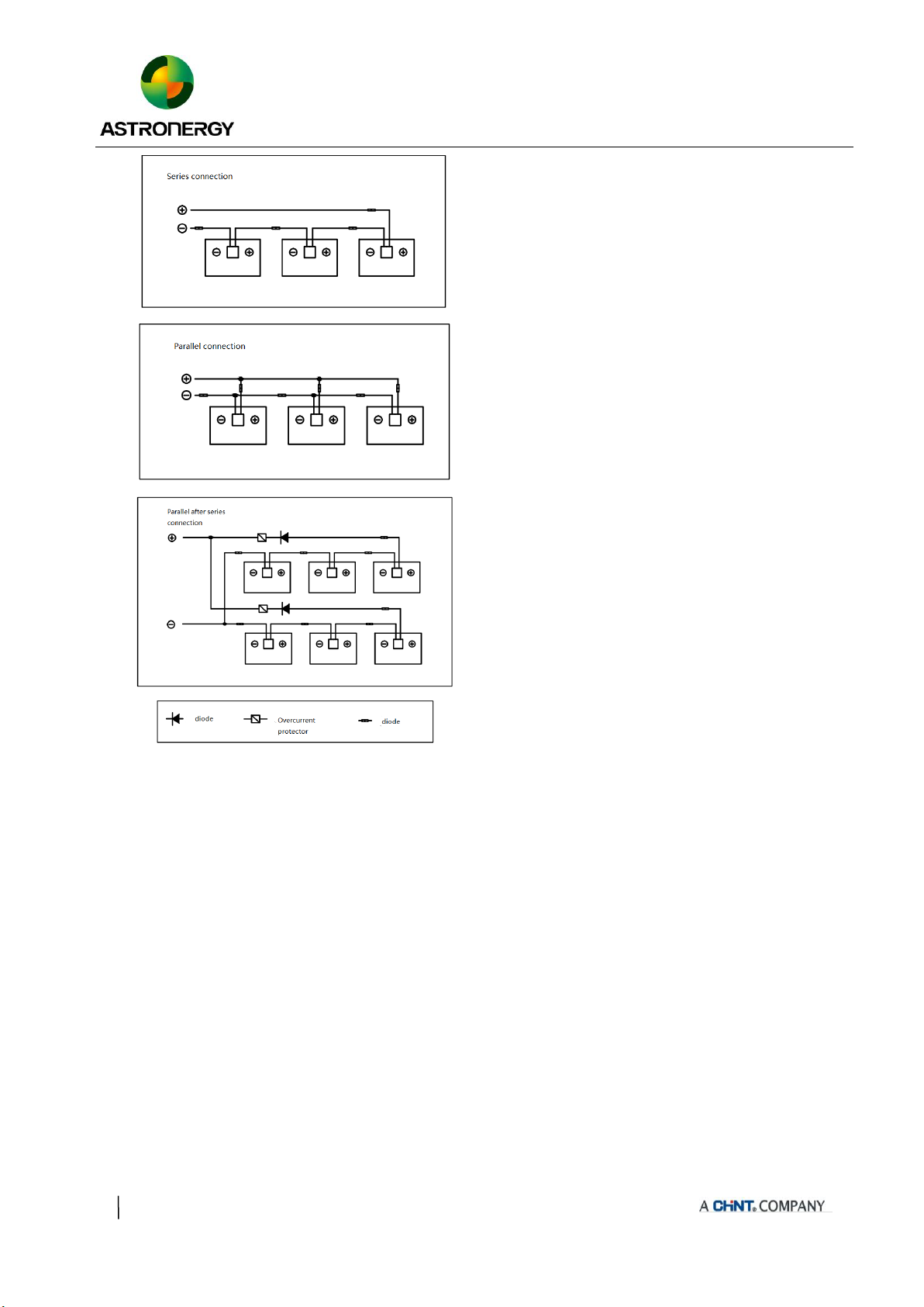
17
Figure 12 Schematic diagram of electrical connection
!note
If one set of arrays is connected to another with the
opposite polarity, it will cause irreparable damage
to the product. Before connecting in parallel, be
sure to confirm the voltage and polarity of each
column. If the measurement finds that the polarity
between the columns is reversed or the voltage
difference is greater than 10V, you must check the
structure and configuration before making the
connection.
The number of photovoltaic modules in series and
parallel must be designed reasonably according to
the system configuration.
Photovoltaic modules of different electrical
performance models cannot be connected in a
string.
Special solar cables and connectors should be used
in the system, and all connections should be
securely tightened. The cable size should be 4mm2
(12 AWG) and must be able to withstand the
maximum open circuit voltage of the photovoltaic
system.
When the cable is fixed on the bracket, it is
necessary to avoid mechanical damage to the cable
or photovoltaic module, and do not press the cable
with force. To fix the cable through the proper way,
a specially designed tying coil and wire clip must
be used to fix it on the bracket. Avoid direct
sunlight and water soaking cables.
Please keep the connector dry and clean, and make
sure that the nut of the connector is tightened
before connecting. Do not connect the connector
when it is found that the connector is wet, dirty, or
in other bad conditions. Avoid direct sunlight and
immersion of the connector in water. Avoid the
connector falling on the ground or roof.
When the photovoltaic module is in a live state,

18
please do not plug or unplug the connector. When it
is necessary to open the connector, ensure that the
photovoltaic module is in a non-working state, and
must use professional unlocking tools and safety
protection measures. It is forbidden to pull or
damage the locking structure.
The junction box of the photovoltaic module
contains bypass diodes connected in parallel to the
battery string of the photovoltaic module. The
bypass diode in the junction box can avoid the
degradation of photovoltaic module performance
caused by shading or covering. Please refer to the
junction box diode specifications provided in the
relevant product specifications.
When a local hot spot phenomenon occurs due to
partial shading or covering of the photovoltaic
module, the diode in the junction box will start to
work, so that the photovoltaic module current will
no longer flow through the hot spot cell, thereby
limiting the heating and performance loss of the
photovoltaic module. When you suspect or find that
the diode is malfunctioning, please contact Chint,
please do not try to open the junction box cover by
yourself.
6.3 Grounded
Chint Solar modules use an anodic oxidized
aluminum frame to resist corrosion. So the frame of
modules should be connected to the equipment
grounding conductor to prevent thunder and electrical
shock. The grounding device should fully contact with
the inside of the aluminum alloy, and penetrate the
surface of the frame oxidation film.
The following is the specific grounding method,
as shown in Figure 13.
Figure 13 Use copper cables to ground the aluminum frame
The grounding requirements must be checked in
accordance with the applicable regulations and
standards before work is started.
Use the marked 5.5 mm grounding holes to ground
the anodized frame. Use one M5 nut, two M5 cut
washers, one M5 plain washer, one M5 spring
washer, and one M5 bolt and the copper wire. All
nuts, bolts, and washers are type M5 and should be
made of stainless steel.
Put the bolt through the cup washer and wrap the
copper wire around the bolt. (Note that the copper
wire cannot be attached directly to the aluminum.)
Put the bolt through the cut washer and then

19
through the hole in the aluminum frame.
Add the spring washer and nut on the other side of
the bolt and tighten to secure all parts. The
tightening torque should be 4~4.5 N•m.
!note
Approve the use of UL-467 certified bonding and
grounding devices, including Burndy (formerly
Wiley Electronics) Washer Electrical Equipment
Bonding (WEEB) and similar devices, such as
barbed washers, that meet the requirements of
UL-467 as suitable for electrical bonding and
grounding PV modules to PV mounting systems.
Other grounding methods may be allowable when
tested with the racking system per UL 2703
requirements.
Please don’t drill any additional grounding hole on
the frame of the modules.
The frame rails have pre-drilled holes marked with
a grounding sign. These holes should be used for
grounding purposes and should not be used for
mounting the modules.
7Maintenance
It is required to perform regular inspection and
maintenance of the modules, especially within
warranty scope. It is the user’s responsibility to the
report to the supplier regarding the damages found in
time.
7.1 Routine inspection
Regular inspections should be made to see if the
photovoltaic modules in the photovoltaic array are
damaged, such as glass breakage, cable breakage,
junction box damage, cell damage, backplane breakage
and other factors that lead to functional and safety
failures of photovoltaic modules. When the above
problems occur, the supplier must be notified in time
to replace the same type of photovoltaic modules.
It is recommended to perform a preventive
inspection every 6 months, and do not replace the
components of the photovoltaic module without
authorization. If electrical or mechanical performance
inspection or maintenance is required, it is
recommended that qualified professionals perform the
operation to avoid electric shock or personal injury.
Routine maintenance measures should be taken
to keep the photovoltaic modules free of snow, bird
droppings, seeds, pollen, leaves, branches, dust, stains,
etc.
7.2 Photovoltaic module cleaning
If the PV module has a sufficient tilt angle (at
least 15°), it is usually not necessary to clean the PV
module (rain will have a self-cleaning effect). If there
is a lot of dirt on the surface of the photovoltaic
module, which has seriously affected the power
generation, use water without detergent and a soft
sponge or brush to rinse the photovoltaic module array
when it is cool throughout the day. Do not scratch or
wipe the dust when it is dry, otherwise it will cause
20
tiny scratches. If there is snow, you can use a brush
with soft bristles to clean the surface of the
photovoltaic module.
For more detailed instructions related to cleaning
and maintenance, please refer to the "Photovoltaic
Module Cleaning Manual".
Modified version and date
Rev1.0, released in June 2018.
Rev1.2, released in August 2021.
Other manuals for Astronergy CHSM6610M
1
This manual suits for next models
17
Table of contents
Other CHINT Control Unit manuals


