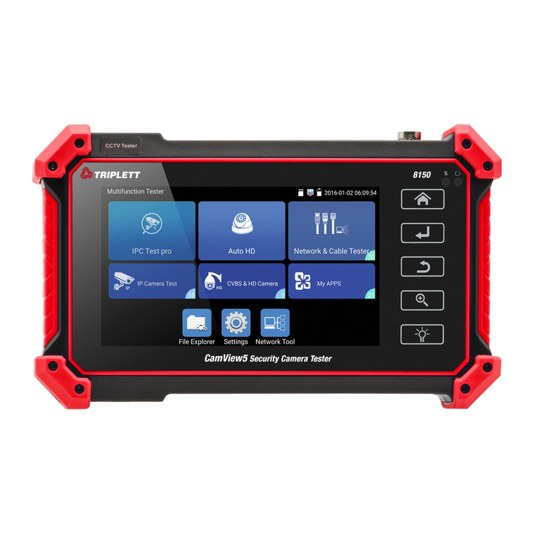
Chipatronic CH-CTAHD5 Operating and maintenance manual

1. Test a Camera
1.1 Insert the 4 pin test cable into the Video In socket on the right side of the tester (yellow socket).
1.2 Connect the camera to the 4 pin connector on the other end of the test cable and turn
the power switch ON. Note that the centre position is OFF.
1.3 The LCD will display the image from the camera if it is working correctly.
With a CVBS camera this will be shown in the upper left hand corner as ANALOG.
With an AHD camera this will be shown as AHD with resolution of the camera.
There is no selection required between CVBS or AHD, the tester detects the video
mode automatically.
2. Test a Monitor
2.1 Using the same test cable, attach a 4 pin Female-to-Female gender changer (CH-4PF2F) to connect
to the input of a 4 pin monitor.
For an RCA input monitor use a 4 pin female to RCA adaptor (CH-4FRCAM).
These adaptors are available as accessories and are not included with the tester.
2.2 Depending on the monitor, power may not be required as the tester outputs 12V through the cable
and some monitors can be powered through this from the tester. Generally the monitor will be installed
and power will be supplied from the vehicle.
2.2 Switch the tester ON and then go to the MENU button located on the top of
the tester. Press the Menu button twice and COLORBAR SIGNAL will be
displayed. Press one of the arrow buttons to select the output required. The
options will cycle through each time the arrow is pressed. With Auto Select
monitors the signal is not usually important as they will work with PAL or
NTSC but other monitors may be set to a specific format.
The colourbar output should be displayed on the monitor being tested.
3. Charging
The charging input is next to the switch on the left side.
Plug the charging cable into the tester and connect to a USB charger, computer or
other USB power source. The small red indicator will show when it is charging.
CH-CTAHD5
Basic User Guide for Vehicle Cameras and Monitors
Please read the instructions prior to use.
●Do not use this device in the rain or in wet conditions as it
may be damaged by water ingress.
●Do not use chemical cleaners on the screen or the case as
this may damage the device.
●Use only the included USB charging cable to charge the
internal battery.
●Ensure that the battery is sufficiently charged before use as
low power may lead to damage either to this device or the
device under test.

Using the CH-CTAHD5 with Hybrid Cameras
The CH-CTAHD5 tester should be used to check and program the Chipatronic Hybrid Series cameras.
Basic testing is carried out as per instructions overleaf and the camera mode will be displayed for a short
time when first connected as below.
Hybrid cameras are designed to suit multiple applications and this is done by re-programming the camera
to suit the application. To do this a proprietary programming cable is required and this is available at no
charge to approved installers.
The programmer is a toggle switch which selects UP, DOWN, LEFT, RIGHT
movements in the menu.
To access the main menu or subsequent sub menus, press the centre button which will display
the Main Menu options. Sub menus are indicated with a return symbol next to the text.
The programming cable must be connected directly to the camera. Changes cannot be made
through an extension cable.
The main change function will be to go from AHD to CVBS as the cameras are supplied in a default of
AHD PAL and will only work with an AHD compatible monitor so if using the camera as a replacement
for an existing unit it will almost always be CVBS that is required.
This is done by way of a Quick Change function using the toggle switch.
With the camera connected and image displayed simply hold the toggle switch to the Left for about 5
seconds or until the image goes black (the camera is re-starting) and the video mode will be changed from
AHD to CVBS and the new mode will be displayed as shown above.
To change back just repeat this except holding the toggle to the Right until the screen goes black as before.
Programming via the On Screen Display (OSD)
There are only two options which should require changes; SPECIAL (7) and ADJUST (8).
No other adjustments should be necessary and many functions will not be supported in this camera.
Please ensure that changes made are suitable before completing the installation as the camera may need to
be removed to access the cable after completion and changes made are done at the user’s own risk.
Use the toggle to move up and down the menus and always use the RETURN option to leave that menu
and then the EXIT option in the MAIN MENU to save the changes and exit the programming.
The SPECIAL menu has multiple options but again the only item normally used is D-EFFECT which
allows the camera to be changed from MIRROR (for reverse view) to normal and the image can be rotated
or flipped vertically if required.
In the ADJUST menu you can check and change the VIDEO OUT format: PAL or NTSC.

D-EFFECT - MIRROR Image Change
Option 2. Use the toggle switch Left / Right to change the selection as
required.
MIRROR On for rear vision/reversing.
MIRROR OFF for use with a DVR or as a forward facing camera.
V-FLIP to turn the image upside down
ROTATE to reverse the image in the flipped image.
By selecting FREEZE ON the ability to change the image in the menu is removed so this locks the change.
ADJUST - VIDEO OUT Change
Option 4. Use the toggle switch Left / Right to change the selection of
the video output format PAL or NTSC.
After making changes always go to the RETURN option at the bottom
of the menu and then the EXIT option to save all changes and go out
of the menu.
The camera can be re-programmed as required so if other changes are
required at a later time, this can be done.
Table of contents
Other Chipatronic Test Equipment manuals

