Hartridge HB385 Installation and operation manual
HL028 Issue 2 (H1407), September 09
World Leaders in Diesel Fuel Injection Test Equipment.
HB385
Portable Mass Overcheck Rig
For AVM & AVM2
Operating & Maintenance Manual
THIS IS AN UNCONTROLLED DOCUMENT downloaded by Lukas Matuska on 16 Feb 2016
Any technical intervention requires certified Hartridge training. Contact Hartridge Ltd for details.

THIS IS AN UNCONTROLLED DOCUMENT downloaded by Lukas Matuska on 16 Feb 2016
Any technical intervention requires certified Hartridge training. Contact Hartridge Ltd for details.

HL028 Issue 2 (H1407), September 09 1
HB385 Portable Mass Overcheck Rig
THIS IS AN UNCONTROLLED DOCUMENT downloaded by Lukas Matuska on 16 Feb 2016
Any technical intervention requires certified Hartridge training. Contact Hartridge Ltd for details.

2HL028 Issue 2 (H1407), September 09
This page intentionally left blank
THIS IS AN UNCONTROLLED DOCUMENT downloaded by Lukas Matuska on 16 Feb 2016
Any technical intervention requires certified Hartridge training. Contact Hartridge Ltd for details.

HARTRIDGE LTD OPERATING & MAINTENANCE MANUAL
HB385
HL028 Issue 2 (H1407), September 09 3
HB385
Portable Mass Overcheck Rig
Operating & Maintenance Manual
CONTENTS
SECTION 1 ......................................................................................... Introduction & Specification
SECTION 2 ......................................................................................................................Installation
SECTION 3 ..........................................................................................................................Systems
SECTION 4 ........................................................................................................................Operating
SECTION 5 ................................................................................................................... Maintenance
SECTION 6 .................................................................................................. Recommended Spares
SECTION 7 ........................................................................................................................ Appendix
THIS IS AN UNCONTROLLED DOCUMENT downloaded by Lukas Matuska on 16 Feb 2016
Any technical intervention requires certified Hartridge training. Contact Hartridge Ltd for details.

OPERATING & MAINTENANCE MANUAL HARTRIDGE LTD
HB385
4HL028 Issue 2 (H1407), September 09
This page intentionally left blank
THIS IS AN UNCONTROLLED DOCUMENT downloaded by Lukas Matuska on 16 Feb 2016
Any technical intervention requires certified Hartridge training. Contact Hartridge Ltd for details.

HARTRIDGE LTD OPERATING & MAINTENANCE MANUAL
HB385
HL028 Issue 2 (H1407), September 09 5
Safety
The following warnings are provided accordance with the provision of the following
European Machinery Safety Directives:
The Machinery Directive 89/392/EEC.
Directive 91/369/EEC, amending Directive 89/392/EEC.
Directive 93/44/EEC. amending Directive 89/392/EEC.
Directive 93/69/EEC, amending Directive 89/392/EEC.
As implemented in the United Kingdom by the Supply of Machinery (Safety) Regulations
1992 (S.I.1992/3073).
Safety at Work - In Use Regulations (Reg. 17(3) - 176)
IT IS IMPORTANT THAT THE FOLLOWING WARNINGS ARE READ AND
HEEDED
Warnings
Isolate the electrical supply before performing any maintenance operations. Do not
work on electrical equipment while voltage is supplied. If such cannot be avoided, e.g.
for measurements, tests or adjustments, have the action carried out by qualified
personnel only.
Safety glasses must be worn when working on this equipment for the following reasons:
The test stand uses calibration fluid which is harmful to the eyes.
Keep the body away from fluid sprays, especially injectors, leaking high pressure pipes
and seals. High pressure injection through the skin can result in fatal injury. In the
event of injection into the skin, seek urgent medical attention. Refer to the Health &
Safety Data Sheets.
Impervious gloves and overalls should be worn if regular contact with ISO4113 test
fluid is likely. Gloves should also be worn when handling parts after measuring, which
may be hot. Refer to the Health & Safety Data Sheets.
Severe injury can be caused by slipping on spilt oils or fluids. All spillage of fluids in the
measuring system area must be dealt with immediately. These can be mopped up and
mineral absorbent material spread over the affected area.
THIS IS AN UNCONTROLLED DOCUMENT downloaded by Lukas Matuska on 16 Feb 2016
Any technical intervention requires certified Hartridge training. Contact Hartridge Ltd for details.
OPERATING & MAINTENANCE MANUAL HARTRIDGE LTD
HB385
6HL028 Issue 2 (H1407), September 09
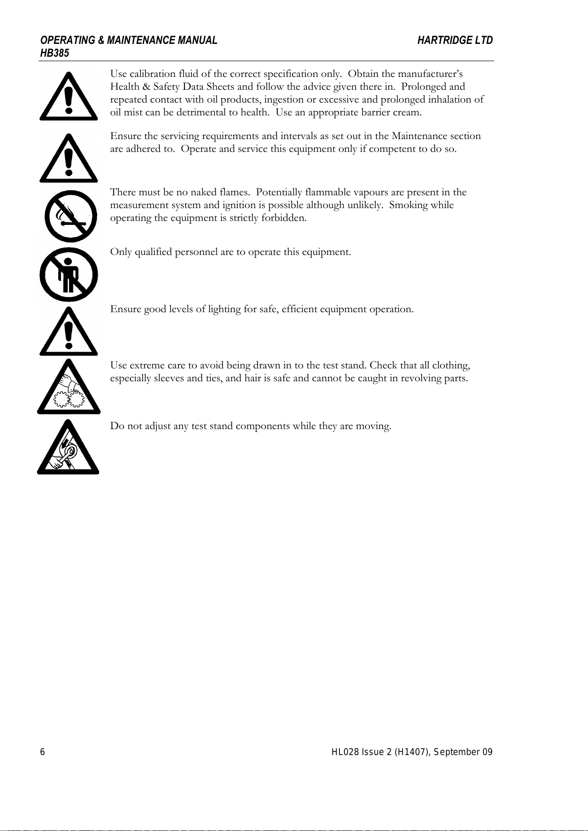
Use calibration fluid of the correct specification only. Obtain the manufacturer’s
Health & Safety Data Sheets and follow the advice given there in. Prolonged and
repeated contact with oil products, ingestion or excessive and prolonged inhalation of
oil mist can be detrimental to health. Use an appropriate barrier cream.
Ensure the servicing requirements and intervals as set out in the Maintenance section
are adhered to. Operate and service this equipment only if competent to do so.
There must be no naked flames. Potentially flammable vapours are present in the
measurement system and ignition is possible although unlikely. Smoking while
operating the equipment is strictly forbidden.
Only qualified personnel are to operate this equipment.
Ensure good levels of lighting for safe, efficient equipment operation.
Use extreme care to avoid being drawn in to the test stand. Check that all clothing,
especially sleeves and ties, and hair is safe and cannot be caught in revolving parts.
Do not adjust any test stand components while they are moving.
THIS IS AN UNCONTROLLED DOCUMENT downloaded by Lukas Matuska on 16 Feb 2016
Any technical intervention requires certified Hartridge training. Contact Hartridge Ltd for details.
HARTRIDGE LTD OPERATING & MAINTENANCE MANUAL
HB385
HL028 Issue 2 (H1407), September 09 7
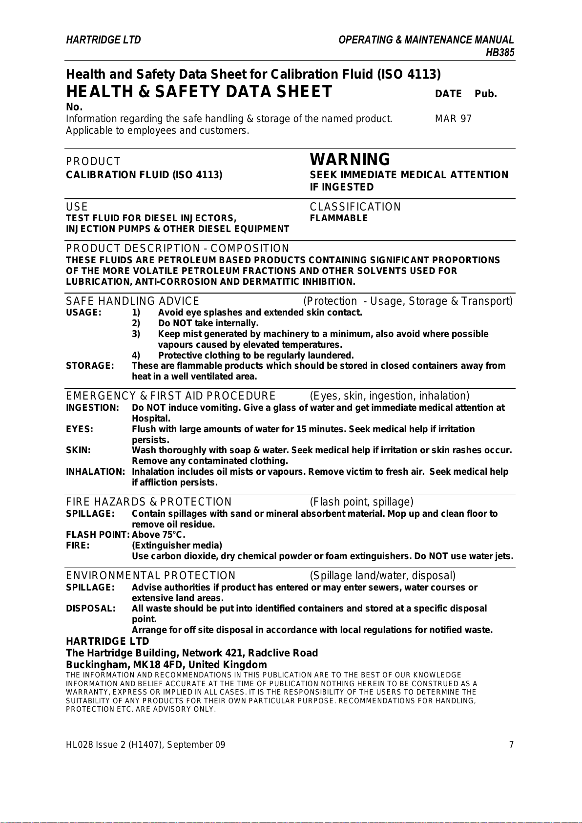
Health and Safety Data Sheet for Calibration Fluid (ISO 4113)
HEALTH & SAFETY DATA SHEET DATE Pub.
No.
Information regarding the safe handling & storage of the named product. MAR 97
Applicable to employees and customers.
PRODUCT WARNING
CALIBRATION FLUID (ISO 4113) SEEK IMMEDIATE MEDICAL ATTENTION
IF INGESTED
USE CLASSIFICATION
TEST FLUID FOR DIESEL INJECTORS, FLAMMABLE
INJECTION PUMPS & OTHER DIESEL EQUIPMENT
PRODUCT DESCRIPTION - COMPOSITION
THESE FLUIDS ARE PETROLEUM BASED PRODUCTS CONTAINING SIGNIFICANT PROPORTIONS
OF THE MORE VOLATILE PETROLEUM FRACTIONS AND OTHER SOLVENTS USED FOR
LUBRICATION, ANTI-CORROSION AND DERMATITIC INHIBITION.
SAFE HANDLING ADVICE (Protection - Usage, Storage & Transport)
USAGE: 1) Avoid eye splashes and extended skin contact.
2) Do NOT take internally.
3) Keep mist generated by machinery to a minimum, also avoid where possible
vapours caused by elevated temperatures.
4) Protective clothing to be regularly laundered.
STORAGE: These are flammable products which should be stored in closed containers away from
heat in a well ventilated area.
EMERGENCY & FIRST AID PROCEDURE (Eyes, skin, ingestion, inhalation)
INGESTION: Do NOT induce vomiting. Give a glass of water and get immediate medical attention at
Hospital.
EYES: Flush with large amounts of water for 15 minutes. Seek medical help if irritation
persists.
SKIN: Wash thoroughly with soap & water. Seek medical help if irritation or skin rashes occur.
Remove any contaminated clothing.
INHALATION: Inhalation includes oil mists or vapours. Remove victim to fresh air. Seek medical help
if affliction persists.
FIRE HAZARDS & PROTECTION (Flash point, spillage)
SPILLAGE: Contain spillages with sand or mineral absorbent material. Mop up and clean floor to
remove oil residue.
FLASH POINT: Above 75°C.
FIRE: (Extinguisher media)
Use carbon dioxide, dry chemical powder or foam extinguishers. Do NOT use water jets.
ENVIRONMENTAL PROTECTION (Spillage land/water, disposal)
SPILLAGE: Advise authorities if product has entered or may enter sewers, water courses or
extensive land areas.
DISPOSAL: All waste should be put into identified containers and stored at a specific disposal
point.
Arrange for off site disposal in accordance with local regulations for notified waste.
HARTRIDGE LTD
The Hartridge Building, Network 421, Radclive Road
Buckingham, MK18 4FD, United Kingdom
THE INFORMATION AND RECOMMENDATIONS IN THIS PUBLICATION ARE TO THE BEST OF OUR KNOWLEDGE
INFORMATION AND BELIEF ACCURATE AT THE TIME OF PUBLICATION NOTHING HEREIN TO BE CONSTRUED AS A
WARRANTY, EXPRESS OR IMPLIED IN ALL CASES. IT IS THE RESPONSIBILITY OF THE USERS TO DETERMINE THE
SUITABILITY OF ANY PRODUCTS FOR THEIR OWN PARTICULAR PURPOSE. RECOMMENDATIONS FOR HANDLING,
PROTECTION ETC. ARE ADVISORY ONLY.
THIS IS AN UNCONTROLLED DOCUMENT downloaded by Lukas Matuska on 16 Feb 2016
Any technical intervention requires certified Hartridge training. Contact Hartridge Ltd for details.

OPERATING & MAINTENANCE MANUAL HARTRIDGE LTD
HB385
8HL028 Issue 2 (H1407), September 09
This page intentionally left blank
THIS IS AN UNCONTROLLED DOCUMENT downloaded by Lukas Matuska on 16 Feb 2016
Any technical intervention requires certified Hartridge training. Contact Hartridge Ltd for details.
HARTRIDGE LTD OPERATING & MAINTENANCE MANUAL
HB385
HL028 Issue 2 (H1407), September 09 9
SECTION 1
Introduction & Specification
CONTENTS
Safety ......................................................................................................................................................................................................5
Warnings.........................................................................................................................................................................5
1. Introduction & Specification ..........................................................................................................................................................11
1.1 Introduction ........................................................................................................................................................11
1.2 Specification .......................................................................................................................................................11
1.2.1. Size & Weight..............................................................................................................................................................11
1.2.2 Services / Information needed ....................................................................................................................................11
1.2.3 Balance .......................................................................................................................................................................11
2.1 Mechanical Installation.......................................................................................................................................15
2.1.1 Site Requirements.......................................................................................................................................................15
2.1.2 Installing the Measuring Assembly..............................................................................................................................15
2.2 Electrical Installation..........................................................................................................................................19
2.2.1 Connections ................................................................................................................................................................19
2.2.2 Set-up..........................................................................................................................................................................19
3.1 Electrical/Electronic System...............................................................................................................................23
3.2 Hydraulic System................................................................................................................................................23
4.1 General................................................................................................................................................................27
4.2 Preparation..........................................................................................................................................................27
4.2.1 General .......................................................................................................................................................................27
4.2.2 AVM/AVM2 Leak Test 1..............................................................................................................................................27
4.2.3. AVM/AVM2 Leak Test 2..............................................................................................................................................27
4.2.4. AVM/AVM2 Flush Test................................................................................................................................................27
4.2.5. Density ........................................................................................................................................................................28
4.2.6. Inlet Pipes ...................................................................................................................................................................28
4.3 Mass Overcheck..................................................................................................................................................29
4.3.1 Warm Up.....................................................................................................................................................................29
4.3.2 Testing ........................................................................................................................................................................29
4.3.3 Calculating The Result ................................................................................................................................................30
5.1 Maintenance........................................................................................................................................................33
5.1.1 Every Use....................................................................................................................................................................33
5.1.2Periodic Maintenance..................................................................................................................................................33
5.1.3 Yearly..........................................................................................................................................................................33
6.1 Recommended Spares List..................................................................................................................................35
7.1 Electrical Circuit Diagram A105A800 (4 Sheets) ..............................................................................................37
THIS IS AN UNCONTROLLED DOCUMENT downloaded by Lukas Matuska on 16 Feb 2016
Any technical intervention requires certified Hartridge training. Contact Hartridge Ltd for details.

OPERATING & MAINTENANCE MANUAL HARTRIDGE LTD
HB385
10 HL028 Issue 2 (H1407), September 09
This page intentionally left blank
THIS IS AN UNCONTROLLED DOCUMENT downloaded by Lukas Matuska on 16 Feb 2016
Any technical intervention requires certified Hartridge training. Contact Hartridge Ltd for details.
HARTRIDGE LTD OPERATING & MAINTENANCE MANUAL
HB385
HL028 Issue 2 (H1407), September 09 11
1. Introduction & Specification
1.1 Introduction
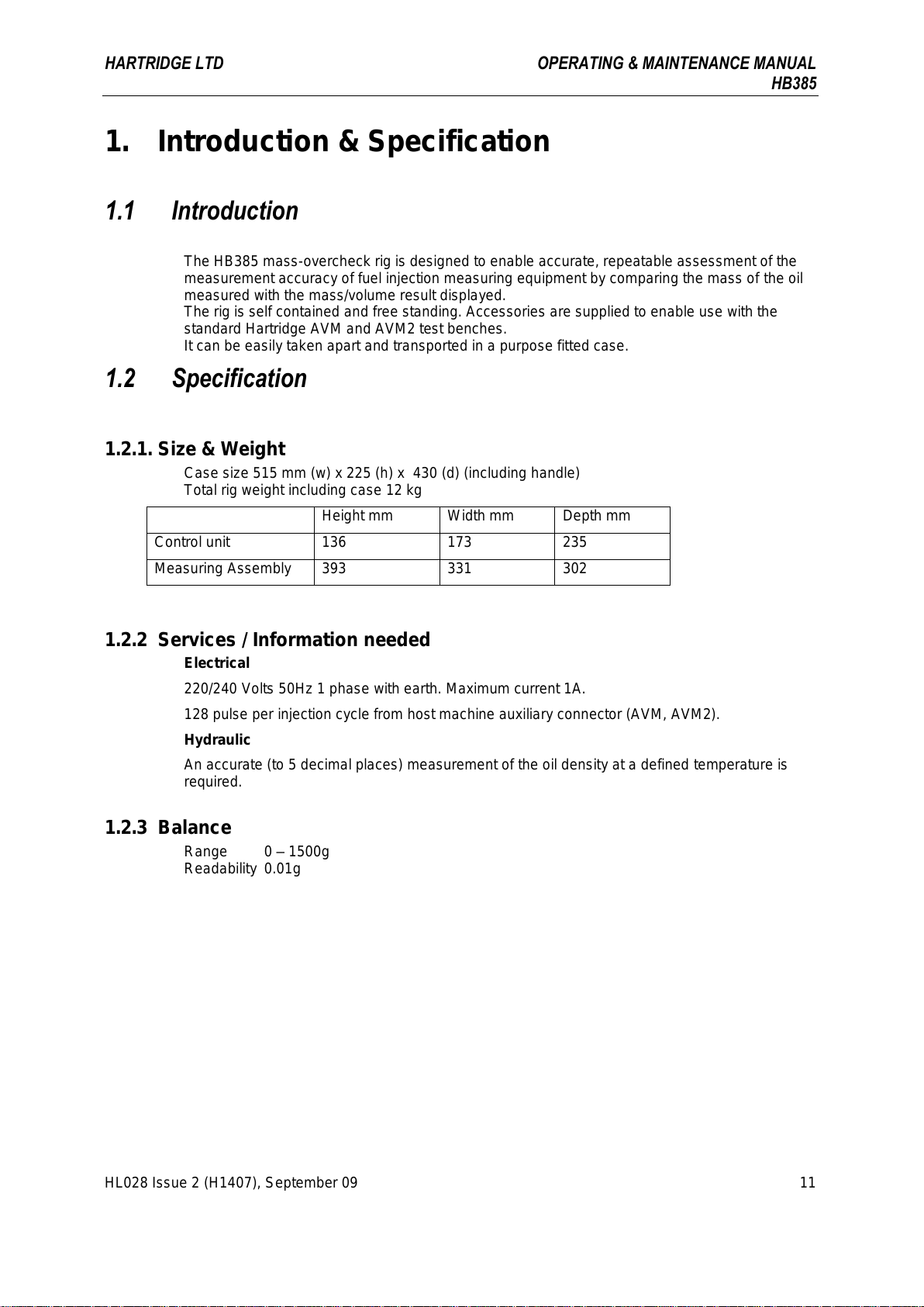
The HB385 mass-overcheck rig is designed to enable accurate, repeatable assessment of the
measurement accuracy of fuel injection measuring equipment by comparing the mass of the oil
measured with the mass/volume result displayed.
The rig is self contained and free standing. Accessories are supplied to enable use with the
standard Hartridge AVM and AVM2 test benches.
It can be easily taken apart and transported in a purpose fitted case.
1.2 Specification
1.2.1. Size & Weight
Case size 515 mm (w) x 225 (h) x 430 (d) (including handle)
Total rig weight including case 12 kg
Height mm
Width mm
Depth mm
Control unit
136
173
235
Measuring Assembly
393
331
302
1.2.2 Services / Information needed
Electrical
220/240 Volts 50Hz 1 phase with earth. Maximum current 1A.
128 pulse per injection cycle from host machine auxiliary connector (AVM, AVM2).
Hydraulic
An accurate (to 5 decimal places) measurement of the oil density at a defined temperature is
required.
1.2.3 Balance
Range 0 –1500g
Readability 0.01g
THIS IS AN UNCONTROLLED DOCUMENT downloaded by Lukas Matuska on 16 Feb 2016
Any technical intervention requires certified Hartridge training. Contact Hartridge Ltd for details.

OPERATING & MAINTENANCE MANUAL HARTRIDGE LTD
HB385
12 HL028 Issue 2 (H1407), September 09
This page intentionally left blank
THIS IS AN UNCONTROLLED DOCUMENT downloaded by Lukas Matuska on 16 Feb 2016
Any technical intervention requires certified Hartridge training. Contact Hartridge Ltd for details.

HARTRIDGE LTD OPERATING & MAINTENANCE MANUAL
HB385
HL028 Issue 2 (H1407), September 09 13
SECTION 2
Installation
THIS IS AN UNCONTROLLED DOCUMENT downloaded by Lukas Matuska on 16 Feb 2016
Any technical intervention requires certified Hartridge training. Contact Hartridge Ltd for details.

OPERATING & MAINTENANCE MANUAL HARTRIDGE LTD
HB385
14 HL028 Issue 2 (H1407), September 09
This page intentionally left blank
THIS IS AN UNCONTROLLED DOCUMENT downloaded by Lukas Matuska on 16 Feb 2016
Any technical intervention requires certified Hartridge training. Contact Hartridge Ltd for details.

HARTRIDGE LTD OPERATING & MAINTENANCE MANUAL
HB385
HL028 Issue 2 (H1407), September 09 15
2.1 Mechanical Installation
2.1.1 Site Requirements
The site selected for the HB385 must satisfy the following conditions:
It must be free from the ingress of dust and dirt.
It must have an electrical supply as defined in Section 1.
It must have flat, level and stable surface to mount the rig on.
The Balance should not be placed in close proximity to a heater or exposed to heat or
direct sunlight.
The Balance must not be exposed to extreme vibrations during weighing.
The Balance must not be exposed to extreme moisture over long periods.
2.1.2 Installing the Measuring Assembly
The measuring assembly consists of the balance, draught shield & base and hydraulic parts.
Refer to Figure 2.1
1. Place the Base Plate on a flat,
level and stable surface within
1.5m of the AVM/AVM2
metering system and the return oil
connection on the AVM/AVM2 facia panel.
2. The Draught Shield is a collapsible assembly. Open the shield so that the side panels are
extended perpendicular to the rear panel. Place the rear panel location tabs into the
corresponding slots at the rear of the Base Plate and push the side panel tabs into the
corresponding slots at each side of the Base Plate until the spring-loaded catches on the
Base Plate lock the shield into position.
3. Rotate the shield top plate into position ensuring the slots are located over the
corresponding tabs of the side panels.
4. Hinge down the shield front panel / door.
Refer to Figure 2.2
5. Fit the Return Beaker into the large hole in the Diverter Valve Support Plate.
6. Fit the diverter valve to the support plate using the two screws supplied and then fit the
support plate to the shield top panel using the two thumbscrews screws supplied.
7. Connect the power jack to the Balance and place the balance on the Base Plate ensuring
the power cable is clear of the balance. Locate the Balance so that the weighing pan is free
to move (not touched by the front panel when it is closed).
8. Observe the Level the Balance using the two levelling feet at the front. Observe the bubble
in the level indicator at the rear of the Balance, adjust the feet to centre the bubble in the
indicator.
This page intentionally left blank
THIS IS AN UNCONTROLLED DOCUMENT downloaded by Lukas Matuska on 16 Feb 2016
Any technical intervention requires certified Hartridge training. Contact Hartridge Ltd for details.
OPERATING & MAINTENANCE MANUAL HARTRIDGE LTD
HB385
16 HL028 Issue 2 (H1407), September 09
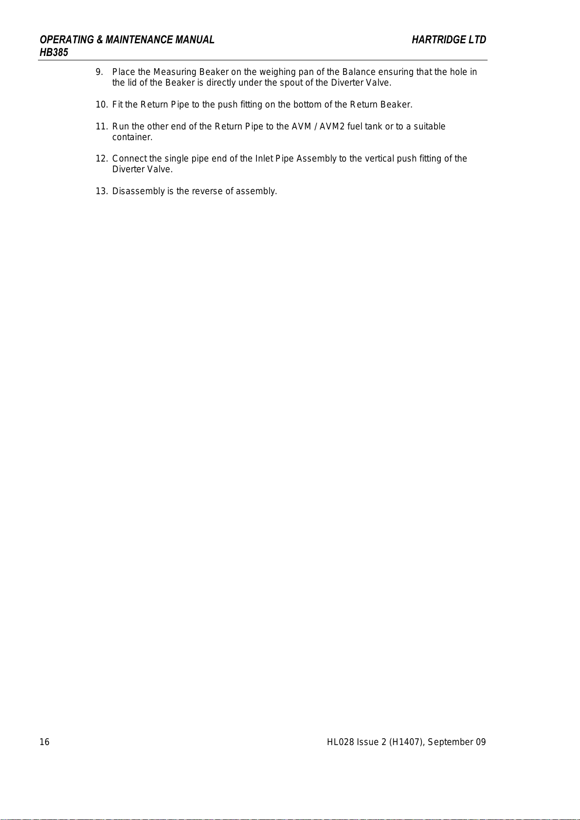
9. Place the Measuring Beaker on the weighing pan of the Balance ensuring that the hole in
the lid of the Beaker is directly under the spout of the Diverter Valve.
10. Fit the Return Pipe to the push fitting on the bottom of the Return Beaker.
11. Run the other end of the Return Pipe to the AVM / AVM2 fuel tank or to a suitable
container.
12. Connect the single pipe end of the Inlet Pipe Assembly to the vertical push fitting of the
Diverter Valve.
13. Disassembly is the reverse of assembly.
THIS IS AN UNCONTROLLED DOCUMENT downloaded by Lukas Matuska on 16 Feb 2016
Any technical intervention requires certified Hartridge training. Contact Hartridge Ltd for details.

HARTRIDGE LTD OPERATING & MAINTENANCE MANUAL
HB385
HL028 Issue 2 (H1407), September 09 17
Figure 2.1 Draught Shield Assembly
THIS IS AN UNCONTROLLED DOCUMENT downloaded by Lukas Matuska on 16 Feb 2016
Any technical intervention requires certified Hartridge training. Contact Hartridge Ltd for details.

OPERATING & MAINTENANCE MANUAL HARTRIDGE LTD
HB385
18 HL028 Issue 2 (H1407), September 09
Figure 2.2 Measuring System Assembly
THIS IS AN UNCONTROLLED DOCUMENT downloaded by Lukas Matuska on 16 Feb 2016
Any technical intervention requires certified Hartridge training. Contact Hartridge Ltd for details.
Table of contents
Other Hartridge Test Equipment manuals


Popular Test Equipment manuals by other brands


Steren
Steren MUL-600 instruction manual

Benetech
Benetech GT5105A instruction manual

NL Acoustics
NL Acoustics NL SONIC TESTER SC10 user manual

Intec
Intec ARGUS 155 manual

Agilent Technologies
Agilent Technologies InfiniiVision 7000B Series Product fact sheet

Bante Instruments
Bante Instruments PHscan30S instruction manual