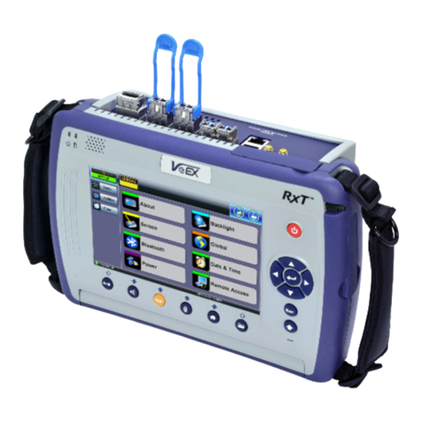
VeEX VePAL TX320s User manual


Table of Contents
1.0 General Information
2.0 Safety Information
3.0 Introduction
3.1 Platform Overview
3.2 Front Panel
3.2.1 LED's
3.2.2 Key Pad
3.2.3 Touch Screen
3.3 Battery
3.3.1 Battery Overdraw Protection
3.4 Hardware Configurations
3.5 Home Screen
3.6 Quick Access Menu
4.0 Getting Started
4.1 Initial Settings
4.1.1 Change language and user interface style
4.1.2 Change the time zone and current time
4.1.3 Change other settings
4.2 Launching Test Applications
4.3 Understanding Test Application GUI
5.0 Utilities
5.1 Platform Settings
5.1.1 About
5.1.2 Screen Calibration
5.1.3 Bluetooth
5.1.4 Power
5.1.5 Backlight
TX300s_Platform_Manual_RevB01
Page 2 of 123

5.1.6 Global Settings
5.1.7 Date and Time
5.1.8 Remote Access
5.1.9 EZ Remote
5.1.10 VF Noise Calibration (Microphone)
5.1.11 Maps Downloader
5.1.12 High Precision Clock Sources
5.2 Help
5.3 VeExpress
5.4 R-Server (Advanced Management)
5.5 Software Upgrade
6.0 File Manager
6.1 File Manager: Working with Saved Results, Profiles, Images
6.2 USB Memory Browser
6.3 Manage SD Card
7.0 Tools
7.1 IP Tools
7.2 Net Wiz
7.3 WiFi Wiz
7.4 ARP Wiz
7.5 Advanced Tools
7.5.1 Fiber Tools
7.5.1.1 Fiber Scope
7.5.1.2 The Importance of Fiber Connector Inspection
7.5.1.3 Connecting the Fiberscope
7.5.1.4 Setup Page 2 and Capture Tab
7.5.2 Optical Power Meter (OPM)
7.5.2.1 Setting Pass/Fail Limits
7.5.3 WiFi Spectrum Analyzer
TX300s_Platform_Manual_RevB01
Page 3 of 123

1.0 General Information
This user manual is suitable for novice, intermediate, and experienced users and is intended to help use the features
and capabilities of VeEX products successfully. It is assumed that the user has basic computer experience and skills,
and is familiar with telecommunication and other concepts related to VeEX product usage, terminology, and safety.
Every effort was made to ensure that the information contained in this user manual is accurate. Information is subject
to change without notice and we accept no responsibility for any errors or omissions. In case of discrepancy, the web
version takes precedence over any printed literature. The content in this manual may vary from the software version
installed in the unit. For condition of use and permission to use these materials for publication in other than the
English language, contact VeEX, Inc.
© Copyright VeEX, Inc. All rights reserved. VeEX, Sunrise Telecom, Digital Lightwave, Air Expert, CaLan,
FaultScout, Fiberizer, MPA, MTT, RXT, VeGrade, VeriPHY, and VeSion, among others, are trademarks or registered
trademarks of VeEX, Inc. and/or its affiliates in the USA and other countries. All trademarks or registered trademarks
are the property of their respective companies. No part of this document may be reproduced or transmitted
electronically or otherwise without written permission from VeEX, Inc.
This manual describes software and/or a device that uses software either developed by VeEX Inc. or licensed by
VeEX, Inc. from third parties. The software is confidential and proprietary of VeEX, Inc. The software is protected by
copyright and contains trade secrets of VeEX, Inc. or VeEX's licensors. The purchaser of this device and/or software,
downloaded or embedded, agrees that it has received a license solely to use the software as embedded in the device
and/or provided by VeEX Inc., and to use it solely as intended and described in this manual. The purchaser is
prohibited from copying, reverse engineering, decompiling, or disassembling the software.
Go back to top Go back to TOC
1.1 Customer Support
For more technical resources, visit www.veexinc.com.
For assistance or questions related to the use of this product, call or e-mail our customer care department for customer
support. Before contacting our customer care department, have the product model, serial number, and software version
ready. Please locate the serial number on the back of the chassis. Please provide this number when contacting VeEX,
Inc. customer care.
Support hours may vary depending on the product.
Product Technical Support
Support is generally available 8:00 AM to 8:00 PM, Eastern Standard Time, Monday to Friday.
Phone: +1 510 651 0500
E-mail: [email protected]
MPA Product Technical Support
Support is generally available 8:30 AM to 5:30 PM, Eastern Standard Time, Monday to Friday.
Phone: +1 877 929 4357
International: +1 727 475 1206
E-mail: [email protected]
Go back to top Go back to TOC
1.2 Warranty
TX300s_Platform_Manual_RevB01
Page 5 of 123

For warranty information on VeEX products, go to https://www.veexinc.com/Support/Warranty.
To activate the warranty, please register your product at https://www.veexinc.com/Support/ProductRegistration.
Go back to top Go back to TOC
1.3 Patent Information
VeEX product hardware and software may be protected by one or more patents on file with the United States Patent
Office.
Go back to top Go back to TOC
1.4 Documentation Conventions
Icons used in this manual:
Marks a helpful tip (action or method), which can save time and
improve usability of the product.
Provides important information needed to use this product and
avoid missteps.
Cautions against and action or inactivity, which can hinder
productivity.
Strongly warns against a condition, an action, or inactivity which
can lead to a health hazard, injury, equipment damage, data loss,
and/or financial losses.
Stop and read before continuing.
Go back to top Go back to TOC
TX300s_Platform_Manual_RevB01
Page 6 of 123

2.0 Safety Information
Safety precautions should be observed during all phases of operation of this instrument. The instrument has been designed to
ensure safe operation however please observe all safety markings and instructions. Do not operate the instrument in the presence
of flammable gases or fumes or any other combustible environment. VeEX Inc. assumes no liability for the customer's failure to
comply with safety precautions and requirements.
Optical Connectors
The test platform displays a laser warning icon when the laser source is active to alert the user about a potentially dangerous
situation. It is recommended to:
1. Deactivate the laser before connecting or disconnecting optical cables or patchcords.
2. Never look directly into an optical patchcord or an optical interface (e.g. CFP, CFP2, CFP4, QSFP+, SFP+, SFP, OTDR, LS,
VFL) while the laser is enabled. Even though optical transceivers are typically fitted with Class 1 lasers, which are considered
eye safe, optical radiation for an extended period can cause irreparable damage to the eyes.
3. Never use a fiber microscope to check the optical connectors when the laser source is active.
Electrical Connectors
Telephone lines may carry dangerous voltages. Always connect the electrical test ports to known test interfaces which carry low
level signals.
Safe Module Handling
While replacing test modules, all work on the open panel must be performed only by suitably qualified personnel who are familiar
with the dangers both to people and to the instrument itself.
Modules are not hot swappable. The platform must be turned off and unplugged from VAC mains when removing or inserting
test modules.
For safety and EMC (Electromagnetic Compatibility), empty module slots must be properly covered with blank panel covers.
Prevent foreign objects from entering the TX300s, before, during and after module exchange or re-configuration process.
They could create short circuits or damage internal fans.
Always store test modules by themselves in individual ESD protected packaging (with no loose elements, like screws or
tools).
Lithium-ion Battery Precautions
Lithium-ion (Li-ion) battery packs are compact and offer high capacity and autonomy, which make them ideal for demanding
applications, like providing long lasting power to portable test equipment. For safety reasons, due to their high energy concentration,
these battery packs and products containing them must be used, charged, handled, and stored properly, according to the
manufacturer’s recommendations.
Li-ion battery packs contain individual Li-ion cells as well as battery monitoring and protection circuitry, sealed in their plastic
container that must not be disassembled or serviced.
The test set unit's battery pack is also fitted with a safety connector to prevent accidental short circuits and reverse polarity.
Always charge the unit's battery pack inside the test platform battery bay using the AC/DC adapter supplied by VeEX.
Do not charge or use the battery pack if any mechanical damage is suspected (shock, impact, puncture, crack, etc).
Do not continue charging the battery if it does not recharge within the expected charging time
Storage: For long term storage, the battery pack should be stored at 20°C/68°F (room temperature), charged to about 30 to
TX300s_Platform_Manual_RevB01
Page 7 of 123

50% of its capacity. Spare battery packs should be charged and used at least once a year to prevent over-discharge (rotate
them regularly).
It is recommended to charge and use battery packs at least every three months. Battery packs must not go without
recharging (reconditioning) for more than six months.
After extended storage, battery packs may reach a deep discharge state or enter into sleep mode. For safety reasons, Li-ion
batteries in deep discharge state may limit the initial charging current (pre-recharge) before starting their regular fast charging
cycle. The pre-charging state may take several hours.
Air transportation of Li-ion batteries is regulated by United Nations' International Air Transportation Association (IATA)
Dangerous Goods Regulations and by country-specific regulations. Please check local regulations and with common carriers
before shipping Li-ion battery packs or products containing relatively large Li-ion battery packs.
Electrical Connectors
Telephone lines may carry dangerous voltages. Always connect the electrical test ports to known test interfaces which carry low
level signals.
ESD: Electrostatic Discharge Sensitive Equipment
Test modules could be affected by electrostatic discharge. To minimize the risk of damage
when replacing or handling test modules, make sure to follow proper ESD procedures and
dissipate any electrostatic charge from your body and tools and use proper grounding gear.
Perform all work at a workplace that is protected against electrostatic build-up and
discharging.
Never touch any exposed contacts, printed circuit boards or electronic components.
Always store test modules in ESD protected packaging.
Wear ESD protection and grounding gear when:
Inserting, extracting, or handling test modules.
Inserting or removing SFPs, XFPs, QSFPs, or CFPs from the platform.
Connecting or disconnecting cables from modules or platform.
Go back to TOC
TX300s_Platform_Manual_RevB01
Page 8 of 123

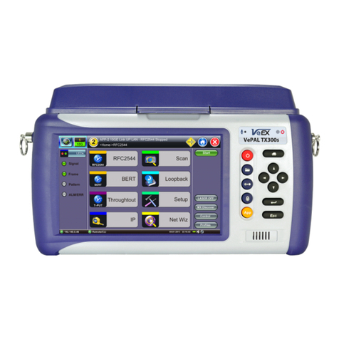
3.0 Introduction to TX300s Series
VeEX®TX300s series test sets are portable test solutions, with flexible configurations, for Core, Transport, Metro and Access
Networks carrying Data, Voice, and Video.
All-in-one hardware platform reduces CAPEX
The VeExpress ecosystem allows users to Buy, Rent, Lease-to-own and share test feature licenses to optimize OPEX
Optimized for the field engineers or technicians installing and maintaining Transport, Carrier Ethernet, Storage Area Network,
Fiber Optics, backhaul and fronthaul mobile networks
Full support for legacy PDH/DSn interfaces with standard connectors (no adapters required)
Test card summary; monitor and manage up to four independent tests
Flexible Software platform allows for the multiple test applications running simultaneously
Multiple factory-installed all-inclusive hardware options, including Single & Dual-port with optional built-in OTDR
Test set connectivity via Ethernet Management interface, Wi-Fi, Bluetooth®, or Cellular Data Card for back office applications
and workflow optimization
Test profiles and thresholds
Fast and efficient test result transfer to USB memory stick
Asset Management: Maintain instrument software, manage test configurations, process measurement results and generate
customer test reports using VeExpress and VeSion cloud services
Optional built-in precision GNSS and chip-scale atomic clock references
Interchangeable Li-ion battery pack extends field testing time
Go back to TOC
TX300s_Platform_Manual_RevB01
Page 9 of 123

3.1 TX300s Overview
Go back to TOC
3.2 Front Panel
3.2.1 LEDs
Power LED: A single LED indicates the power state of the unit.
The LED is off when the unit is powered off.
The LED is green when the unit is powered on.
The LED is orange when the unit is connected to the AC Mains and powered off (charging).
Soft LEDs: Each tests module offers detailed soft LEDs and indicators in its test application.
TX300s_Platform_Manual_RevB01
Page 10 of 123

3.2.2 Key pad
Power: Press for 2 seconds to turn the test set ON or OFF (prevents accidental ON/OFF).
Save Test Results: Saves the current Test Results with customized or auto naming
(yyyymmdd-hhmmss format). The F1 key on standard keyboards can be used when
controlled via VNC
Clear History: Resets blinking LED reminders of past Errors or Alarms. Test results are not
affected. The F2 key on standard keyboards can be used when controlled via VNC
Lock/Unlock Touch Screen: Can also be programmed to capture Screen Shots (>Utilities
>Settings >Global >Save Settings). Use the F3 in standard keyboards
Test Application Selector: Quickly switches back-and-forth between two active test
applications
Home: Quickly bring users back to the Main Menu
Cursor Keys: Application dependent may offer alternative GUI Navigation to touch screen
(e.g. while wearing gloves in cold weather)
Enter: Application dependent
Escape: Application dependent
Go back to TOC
3.2.3 Touch Screen
The LCD supports touch screen operation. To operate the touch screen to navigate the menus and tabs, use the stylus located on
the right side of the unit. Please observe the following precautions:
Never use excessive pressure on the touch screen as this may damage its functionality.
Never use sharp objects such as a pen, screwdriver, etc., as this may damage the surface.
Clean the surface of the touch screen using a soft cloth and mild detergent only. Do not use alcohol.
Go back to TOC
3.3 Battery
The test set platform is equipped with a smart Li-ion rechargeable battery pack, which is located on the rear of the unit. The battery
will be partially charged upon delivery, so it is recommended to fully charge the battery before use. Please charge the battery at
room temperature to preserve its life and to obtain maximum charge. The battery is charged during operation, provided the unit is
connected to the AC Mains using the supplied AC adapter. Removing the battery while the unit is powered on is not recommended -
this may result in damage. Remove the rubber cover on the right side to connect the AC Main adapter to the unit.
Make sure that the key is aligned while plugging in the AC adapter to the unit. If it is not aligned,the plug will not connect to the
unit and using force will damage the connector.
Battery Charging time
The total charging time depends on the remaining battery capacity percentage and the actual current load in the TX300s. An idle
TX300s would recharge faster than an active one.
TX300s_Platform_Manual_RevB01
Page 11 of 123

Attention!
For safety reasons, the battery charging time is always limited to a
maximum of three hours
If the TX300s is being used while charging and a full charge (100%
capacity) cannot be achieved within three hours, the charging will
automatically stop.
To resume charging, unplug the AC/DC adapter and let the TS300s work
on battery power for a minute or two and plug the AC/DC back in. This will
reset the charging circuitry.
Warning!
DO NOT disconnect the AC/DC power supply when the TX300s is running
under heavy load conditions (greater than the battery's current ratings),
such as certain multi-module multi-test applications.
If the current required is too high, but still within the battery's limits, a
warning message would be displayed when the AC/DC adapter is
unplugged, while all the tests are properly closed and TX300s shuts down.
Under overload conditions, the battery may not be able to supply enough
current to keep the test scenario running and its safety mechanisms may
shut the battery down without warning and test results may be lost.
Battery Safety precautions
For more information on safety precautions for batteries, see Lithium-ion Battery Precautions.
Go back to TOC
Battery Power Capacity
Total Battery Power: 83.7 Watt Hours.
TX300s Platform test platform: 20 Watts
AC/DC Power Supply
When using the AC/DC power supply adapter, the total power capacity provided is 88 Watts.
Go back to TOC
3.3.1 Battery Overdraw Protection
When battery capacity declines to 10%, an audible alarm and pop-up warning displays a notification to plug in the A/C adapter or
shut down the unit. If this warning is ignored and the battery capacity is allowed to decline to under 5%, the unit will initiate a
shutdown to protect the battery from damage and for safety.
If an event, such as the AC/DC adapter being unplugged, a power interruption occurs or some other event triggers the power load to
exceed the 95W battery limit, the unit will initiate an emergency shutdown to protect the battery from damage and for safety.
During an emergency shutdown all modules power is switched off. No test files (results or configurations) are saved.
Go back to TOC
3.4 Hardware Configurations
The following are examples of some test modules available for the TX300s platform. Please refer to their individual datasheets and
manuals for further details. For an up-to-date list of modules available, please visit www.veexinc.com/TX300S
Two 300SM Modules - Two Single Port Groups
TX300s_Platform_Manual_RevB01
Page 12 of 123

Configurable as Fully-Loaded Dual Port Group (Allows independent Dual Tests)
Universal multi-service test modules offer OTN/SDH/SONET/PDH/DSn, Carrier Ethernet, MPLS, Fibre Channel,
CPRI/OBSAI, Synchronization and more
Additional Technologies, Rates and Test Features can be added later, via SW licenses
One 300SM Module - Single Port Group
Configurable as an economical Single Port Group (Single Test)
Universal multi-service test module offers OTN/SDH/SONET/PDH/DSn, Carrier Ethernet, MPLS, Fibre Channel,
CPRI/OBSAI, Synchronization and more
Additional Technologies, Rates and Test Features can be added later, via SW licenses
One 320S Module - Single Port Group
Configurable as an economical Single-Group Dual-Port option (Dual Tests)
Universal multi-service test module offers OTN/SDH/SONET/PDH/DSn, Carrier Ethernet, MPLS, Fibre Channel,
TX300s_Platform_Manual_RevB01
Page 13 of 123

CPRI/OBSAI, Synchronization and more
Additional Technologies, Rates and Test Features can be added later, via SW licenses Perfect companion to the OTDR
hardware option
One 340SM Module - Single Port Group
Flexible, all-in-one multi-service test solution, from 64kbps to 16 Gbps (can be combined with 100G and OTDR modules)
Transport, Core, Metro, SAN, Backhaul and Fronthaul applications
Supports up to four test port groups with independent and simultaneous measurements
Test cards summary provides an overview of up to four running tests, as well as test application switching and management
fuctions
One 100G Module
Available with CFP4 or QSFP28 for 100GE and OTU4 applications
Supports IEEE 802.3bj Clause 91RS-FEC as required for SR4 (QSFP28)
QSFP+ for 40GE, OTU3
TX300s_Platform_Manual_RevB01
Page 14 of 123

External clock interface
150 ppm clock offset generation
Soft LED indicators
OTDR Module
Fiber Optics, Transport and Service Verification, Testing & Troubleshooting
OTDR: Standard (+7dBm), High-power (+23 dBm) and PON (+23 dBm) versions
OTDR, OPM and VFL ports with interchangeable optical bulkhead connectors
This factory-installed option can be combined with any of the multi-service modules
Go back to TOC
TX300s_Platform_Manual_RevB01
Page 15 of 123

3.5 Home Screen
Go back to TOC
3.6 Quick Access Menu
This multi-tasking section provides convenient and immediate access to system features, connectivity, accessories, results, etc.
Those features are always available, independently of whether tests are running or not.
TX300s_Platform_Manual_RevB01
Page 16 of 123

International user interface style USA Interface style
4.0 Getting Started - TX300s
4.1 Initial Settings
4.1.1 Change language and user interface style
Before using the platform, set the language and user interface style as needed. By default, the user interface style is set to USA if
the unit is shipped to North America and to International if the unit is shipped to outside North America.
To change the GUI language and user interface style
1. Tap Utilities, and then tap Settings.
2. Tap the Global option.
3. Select the language from the Language drop-down list box.
4. Select the user interface style from the User Interface drop-down list box.
International: Provides layer-based SDH/PDH configuration menus with access to detailed settings
USA: Provides simplified application-based SONET/DSn menu with more automation. The Advanced Mode option
displays the configuration menu for additional settings
Go back to TOC
4.1.2 Change the time zone and current time
To manually change the Date & Time
1. Tap Utilities, and then tap Settings.
2. Tap the Date & Time option.
3. Select the date and current time from the drop-down list boxes.
4. Tap Apply.
To synchronize the time to the GPS
The GPS receiver hardware option must be installed. For more information on the atomic clock and relative phase monitoring, see
5.1.12 High Precision Clock Source.
Go back to TOC
4.1.3 Change other settings
For more information on changing other global settings, such as units of measurement, profile and results save preferences,
password, etc., see Utilities.
Go back to TOC
TX300s_Platform_Manual_RevB01
Page 17 of 123

4.2 Launching Test Applications
The Test Cards summary/status screen offers intuitive test application management (launch, monitor, switching and release). Each
test card is associated with a test module (orange numbers) and their individual test port groups (white numbers); capable of
showing two, three or four possible tests, depending on the capabilities of the modules installed in the test platform.
Test Cards are aligned in the same order of modules and ports they represent, for easy identification and correlation.
Select the test card related to the desired module and port group, to start a test mode configuration, then follow the
already familiar process.
Use the chassis yellow App rubber button to quickly toggle among the active tests (up to four independent tests).
Use the Test Cards icon, on the top-left corner of the screen, to see a summary of all running tests, available test
resources, switch to a different test (touch on the status box with the magnifying glass icon), and release tests.
Once a new test port group has been selected, using the New button on its Test Card, users can select the specific
test interface type (Test Port), if required. Then the test module will present a menu of all applicable technologies
(protocols) available for the selected port (QSFP-DD, CFP, SFP+, BNC, Bantam, RJ48, etc.)
This procedure can be started at any time, from any screen or menu.
1. Identify an available Test Card (gray) and tap on the New button to launch the Test Mode Selection menu.
Depending on the hardware configuration, up to four tests can run simultaneously.
Some application allocate two test cards or port groups and they are normally available from Port 1 (e.g. router wrap-around
tests, monitoring, etc.)
TX300s_Platform_Manual_RevB01
Page 18 of 123

2. Select the Technology Group.
3. Select the desired Test Mode based on the application to be tested.
4. Tap on the OK button to confirm.
The test port group is assigned to the selected test application.
Required software/firmware is loaded.
Go back to TOC
4.3 Understanding Test Application GUI
A. Background Test Application
Tap this button to bring its GUI forward.
Or press the App rubber button to toggle.
B. Active Test Application GUI
- Shows the Test Port Group being used and the Test App ID (Rate / Technology).
Tap this button to release the Test App or change its Test Mode.
C. Test Application Menu
Lists all test Functions, Applications and Tools available for the selected test mode.
Setup = Port and Test Signal configuration.
D. LEDs - Test Signal Status.
E. History - Clears past events reminder (blinking).
F. Current test interface line rates.
G. Action buttons section.
This vertical section displays direct access functions applicable to each specific Test Mode, such as Start/Stop test, Laser
control, Error and Alarm injection, Start protocol capture, etc.
Most of these buttons offer immediate action. A few open a configuration menu.
TX300s_Platform_Manual_RevB01
Page 19 of 123

5.0 Utilities
5.1 Platform Settings
This section provides settings for the global parameters of the test set or platform (system settings).
Settings Menu
Go back to TOC
5.1.1 About
This section provides information about the software version, serial number, and MAC address of the management port of the unit,
as well as a list of software licenses (optional test features) currently loaded in the test set.
Utility Settings - About
TX300s_Platform_Manual_RevB01

Page 20 of 123
This manual suits for next models
4
Table of contents
Other VeEX Test Equipment manuals

VeEX
VeEX OTDR FX150+ Series User manual

VeEX
VeEX VePAL TX300 User manual

VeEX
VeEX TX300s User manual

VeEX
VeEX VePAL TX300 User manual

VeEX
VeEX VePAL TX300 User manual

VeEX
VeEX CX380C User manual

VeEX
VeEX VePAL TX300 User manual

VeEX
VeEX MTTplus User manual

VeEX
VeEX UX400 User manual

VeEX
VeEX MTX150 Series User manual
Popular Test Equipment manuals by other brands

Testboy
Testboy Profi LED Plus operating instructions

SIGLENT
SIGLENT SDS1102X user manual

auray
auray CFT-ET Series owner's manual

Keysight Technologies
Keysight Technologies U3042AM08 User's and service guide

DRUCK & TEMPERATUR Leitenberger
DRUCK & TEMPERATUR Leitenberger LR-Cal TLDMM operating manual

merlam
merlam M201 Addendum to user's manual