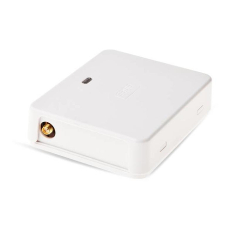
CHIYU BF-1010 User manual

BF-1010
User Manual
Document Version 2.0
Web Version 1.8, Jan 15 2018
Firmware Version 1.11.09, Oct 3 2019

【】
Content
-BF-1010 Instruction-................................................................................................................1
Ⅰ、Hardware Introduction....................................................................................................1
Appearance .............................................................................................................1
Specifications..........................................................................................................1
Endpoint description ...............................................................................................2
Ⅱ、Product description ........................................................................................................3
Feature of BF-1010.................................................................................................3
Ⅲ、Login WEB .....................................................................................................................4
Preparation ..............................................................................................................4
How to search BF-1010 ..........................................................................................4
Use a web browser to enter the BF-1010 Web configuration interface..................7
Ⅳ、Web function description................................................................................................8
Basic Setup..............................................................................................................8
1、Network Setting ................................................................................................8
(1) STATIC IP ........................................................................................................8
Function Description................................................................................8
(2) DHCP CLIENT .................................................................................................9
Function Description................................................................................9
(3) PPPoE..............................................................................................................10
Function Description..............................................................................10
Network operation mode.......................................................................................11
Data PORT 1.........................................................................................................11
(1) TCP Server ......................................................................................................11
Function Description..............................................................................12
(2) TCP Client.......................................................................................................13
Function Description..............................................................................13
(3) UDP Client ......................................................................................................14
Function Description..............................................................................14
Data PORT 2.........................................................................................................15
(1) TCP Server ......................................................................................................15
Function Description..............................................................................15
(2) TCP Client.......................................................................................................16
Function Description..............................................................................16
(3) UDP Client ......................................................................................................17
Function Description..............................................................................17
I/O PORT ..............................................................................................................18
(1) TCP Server ......................................................................................................18
Function Description..............................................................................18
(2) TCP Client.......................................................................................................19
Function Description..............................................................................19
(3) UDP Client ......................................................................................................20
Function Description..............................................................................20
Serial operation mode ...........................................................................................21
(1) PORT 1............................................................................................................21
Function Description..............................................................................21
(2) PORT 2............................................................................................................22

Function Description..............................................................................22
I/O Normal State/Trigger Mapping Setup ............................................................23
Function Description..............................................................................23
VMS Setting..........................................................................................................24
Function Description..............................................................................24
Sensor Threshold ..................................................................................................25
Function Description..............................................................................25
I/O Auto Report Setup ..........................................................................................26
Function Description..............................................................................26
E-Mail Alert..........................................................................................................27
Function Description..............................................................................27
System Clock Setup ..............................................................................................28
Function Description..............................................................................28
System Log ...........................................................................................................29
Function Description..............................................................................29
Management..........................................................................................................30
1、Device Administration Setting........................................................................30
Function Description..............................................................................31
2、System Status Monitor....................................................................................32
Function Description..............................................................................33
3、I/O Status ........................................................................................................34
Function Description..............................................................................34
4、Backup & Restore Configuration....................................................................35
Function Description..............................................................................35
5、Firmware Upgrade ..........................................................................................36
Function Description..............................................................................36
6、PING ...............................................................................................................37
Function Description..............................................................................37
Copyright @ 2011. All Rights Reserved.
All trademarks and trade names are the properties of their respective owners.

1
-BF-1010 Instruction-
Ⅰ、Hardware Introduction
Appearance
Specifications
N
ame Specifications
CPU 16 Bits, 100MHZ
Memory 512KB Flash & 1MB SDRAM
Setting interface Web management interface
Input point 1. 10 groups of digital input points
2. Interconnection via terminal block
3. Photocoupler isolation: 2,500V (DC)
4. Voltage overload protection: 70V (DC)
Output point 1. 10 sets of digital output points
2. Use terminal block to interface;
3. Photocoupler isolation: 2,500V (DC)
4. Built-in relay (made in Japan): DC30V, 1A
Web interface 1. 1 RJ-45 ports
2. 10 / 100Base-T full / half duplex support
3. Automatic jumper detection
RS-485 interface 1. 2 groups of RS-485 / 2. Connect with terminal block
LED display 1. Power status light
2. Network status light
3. 2 groups of RS-485 status lights
4. 10 groups of digital input status status lights
5. 10 sets of digital output status lights
6. Extended interface data transmission status lights
Power supply DC 9~24V / 0.5A~1A
ESD ;
Contact Discharge 4KV Air Discharge 8KV
Operating temperature 0℃~ 65℃
Operating humidity 5 ~ 95%RH
Storage temperature -20℃~ 85℃
Weight / Dimensions 525 g / 135X115X35 mm

2
Endpoint description

3
Ⅱ、Product description
BF-1010 is a controller with 10 sets of DIO, which can control DIO remotely through TCP / IP
communication.
The real-time operating system and the complete TCP / IP protocol make the BF-1010 not only
provide a sound and efficient system to connect your device to the network, but also easy to install
and establish a network connection.
The BF-1010's WEB setting interface is not only easy to operate but also has no operating system
platform limitations.
Feature of BF-1010
BF-1010 supports 3 network operation modes: TCP server, TCP client and UDP, users can
choose the appropriate connection method according to their needs.
Support DHCP Client function, after starting this function, BF-1010 can be started from DHCP
Server when the system is started. Get the TCP / IP settings, including IP address, default
gateway IP and DNS server.
Support PPPoE function, PPPoE is a protocol to establish a connection with the remote host
through the DSL connection analog dial-up connection to the Internet.
Support dynamic DNS function, which allows BF-1010 to connect with dynamic wide area IP
with a fixed name (Domain Name), making it easier for hosts in different locations to access BF-
1010 through the Internet.
Automatically detect 10/100 network environment.
Allow users to access and manage BF-1010 under any operating system through Internet
browsers such as IE and Netscape.
Allow users to back up system parameters to file storage and restore system parameters from the
backed up files. The files backed up for security reasons will be stored in an encrypted manner.
BF-1010 has a total of 10 groups of DI / 10 sets of DO. The simple web page setting method
allows users to avoid programming background.
Support SMTP Client function, which allows BF-1010 to send alarm messages to your mobile
phone via e-mail or SMS.
Provide remote reset CGI Command, and I / O Control CGI commands

4
Ⅲ、Login WEB
BF-1010 contains an HTTP server, so you can connect to BF-1010 through a web browser and set
BF-1010.
Preparation
Before setting BF-1010, please confirm:
The computer can establish a physical connection with the BF-1010. The computer and the BF-
1010 must be in the same domain at the same time. The BF-1010 has been installed and powered
on.
If the default IP address (192.168.0.125) of BF-1010 has been adopted by other devices, you
should turn off the other devices until the setting is completed and assign a new IP address to BF-
1010.
How to search BF-1010
1. After installing BF-1010 and confirming that the network cable has been installed, use BF-
1010 to search the IP address:
IP Search can find all the BF-1010 in the domain. The desktop icon is as follows:
2. After clicking the IP Search icon on the desktop, a window will appear, as shown below:

5
3. After the IP Search window appears, it will display all BF-1010 currently in the domain
to which it belongs. The window will display BF-1010's Terminal ID, Model Name, IP
Address, Subnet Mark, Gateway, Mac Address, Software IP, click BF-1010 displayed in
the window, the relevant information of the selected BF-1010 will be displayed at the
bottom of the window, as shown below:
4. The BF-1010 information displayed at the bottom of the window can be directly
modified to the BF-1010. The parts that can be modified are IP Address, Subnet Mask,
Gateway, Software IP, Software Port, Terminal ID. After modifying the required
information (MAC Address cannot be modified), after clicking Alter, the message
window of successful modification will be displayed, as shown below:

6
5. After the modification is successful, if you want to confirm whether the modification is
correct, click Refresh to refresh the information in the window (Figure -1), you can check
whether the BF-1010 information in the domain belongs to have been matched. Exit to
leave the window.
6. After the modification is completed, the IP address of BF-1010 has already conformed to
the domain to which it belongs. If you want to enter the web of BF-1010 at this time,
there are the following two methods:
(1) After starting IP Search, select the BF-1010 to be entered and then double-click to enter
the selected BF-1010 webpage
(2) After opening the web browser, enter the BF-1010 IP address where you want to enter
the web address, you can enter the BF-1010 web page
Remark:
WINDOWS XP:
《Step 1》
Click WINDOWS XP My PC to open and select the left Control panel. Please switch to
the traditional view and select the network connection.
《Step 2》
Click on the regional connection to select the content will jump out of the regional
connection settings, click Internet Protocol (TCP / IP), click to set the same domain as
the BF-1010.

7
Use a web browser to enter the BF-1010 Web configuration
interface
1. After starting the web browser, enter http: // and the IP address of BF-1010 in the address
bar, for example: use the default IP address of BF-1010: http://192.168.0.125
2. If the connection fails, you should check
Is the BF-1010 installed correctly and is the power on?
Whether the local area network connection is normal, you can use the start
toolbarExecuteEnter cmd to open the MS-DOS window, enter the "ping"
command to test the connection of BF-1010, enter the command: ping 192.168.0.125
If no response is received, it means that the connection is not working properly or the IP
address of the computer does not match the IP address of BF-1010.
Set the computer IP to the IP address of the same network segment as BF-1010. If the
computer uses a fixed IP address, the address must be between 192.168.0.1 ~
192.168.0.124 or 192.168.0.126 ~ 192.168.0.254. Within the range, in order to be
compatible with the BF-1010's default IP address 192.168.0.66, the setting of "Subnet
Mask" must be 255.255.255.0
3. If the connection with BF-1010 is successful, a window for entering the user account
password will be displayed. The default value of the user name and password is: admin /
admin
4. After entering the account password, you will enter the BF-1010 web configuration
interface. After entering, the BF-1010 web configuration interface will be displayed. This
page is the first screen to enter the web configuration interface

8
Ⅳ、Web function description
Basic Setup
1、Network Setting
(1) STATIC IP
Function Description
IP Address: Set the IP address of BF-1010, the default value is 192.168.0.125
Subnet mask: Set the Subnet mask of BF-1010, the default value is 255.255.255.0
Gateway: Set the default Gateway of BF-1010, the default value is 192.168.0.254
Primary DNS: Set the DNS of BF-1010, the default value is 168.95.1.1

9
(2) DHCP CLIENT
Function Description
Host Name (optional): Enter host name, the default is BF-1010, non-required field.

10
(3) PPPoE
Function Description
User Name: Enter user name, up to 47 characters.
Password: Enter user password, up to 35 characters
Service Name (optional): Enter the server name, up to 47 characters (optional fields) Close
Connection when Idle Time Over:
1. Set the idle disconnection time (seconds), the default value is 0 seconds, the range is 0 ~
4294967295
2. If you want to keep BF-1010 and ISP connected at any time, you must set this value to 0,
otherwise, if there is nodata transmission exceeding the set time, it will automatically
disconnect with PPPoE
PPPoE with Fixed IP Address:
1. When PPPoE uses fixed IP, enter ENABLE after selecting ENABLE
2.The default value is DISABLE

11
Network operation mode
Data PORT 1
(1) TCP Server

12
Function Description
Local Listen Port Number:
If the device is using the TCP/IP protocol to drive the data transfer via remote instructions, the
Serial Server Mode must be set to TCP SERVER and the LISTEN PORT NUMBER configuration
and monitoring side must be the same value, the default is 50001
Close Connection When Remote Idle:
1. Set the idle disconnection time, the default value is 0 seconds, the range is 0 ~ 32768
2. When you want to keep the BF-1010 connected to the monitoring at all times, you must set this
value to 0, otherwise the segment connection will be automatically cut when no data is transmitted
on the line beyond the set time
Max Connection:
Set the maximum number of TCP connections, the maximum can be set to 3 TCP connections, the
default value is 3
Access Password:
To ensure the security of datas, the user can set a password to enter and control. When the datas are
transferred, the correct password must be entered to obtain permission before proceeding to the next
steps. Enter up to 31 characters.
Keep Alive Check:
When connected, a ping packet is sent to the Gateway Router to ensure the connection every 30
seconds.

13
(2) TCP Client
Function Description
Destination IP Address 1:
Set the remote IP address and port number of the first group, the range of PORT is 0 ~ 65535, the
default is 50000.
Destination IP Address 2:
Set the remote IP address and port number of the second group, the range of PORT is 0 ~ 65535, the
default is 50000.
Destination IP Address 3:
Set the remote IP address and port number of the third group, the range of PORT is 0 ~ 65535, the
default is 50000.
Keep Alive Check:
When connected, a ping packet is sent to the Gateway Router to ensure the connection every 30
seconds.

14
(3) UDP Client
Function Description
Destination IP Address 1:
Set the remote IP address and port number of the first group, the range of PORT is 0 ~ 65535, the
default value is 50000.
Destination IP Address 2:
Set the remote IP address and port number of the second group, the range of PORT is 0 ~ 65535, the
default value is 50000.
Destination IP Address 3:
Set the remote IP address and port number of the third group, the range of PORT is 0 ~ 65535, the
default value is 50000.
Local Listen Port:
Set the local receiving port number, the default value is 50000, the range is 0 ~ 65535.
Keep Alive Check:
When connected, a ping packet is sent to the Gateway Router to ensure the connection every 30
seconds.

15
Data PORT 2
(1) TCP Server
Function Description
Local Listen Port Number:
If the device is using the TCP/IP protocol to drive the data transfer via remote instructions, the
Serial Server Mode must be set to TCP SERVER and the LISTEN PORT NUMBER setting and
monitoring side must be the same value. The default value is 50001.
Close Connection When Remote Idle:
Set the idle disconnection time, the default value is 30 seconds, the range is 0 ~ 32768.
When you want to maintain the connection between BF-1010 and the monitoring terminal at any
time, you must set the value to 0, otherwise when there is no data on the line and the
transmission exceeds the set time, the connection will be automatically disconnected.
Max Connection:
Set the maximum number of TCP connections, up to 3 TCP connections, the default value is 3.
Access Password:
To ensure the security of assets, the user can set a password to enter and control. When the
assets are transferred, the correct password must be entered to obtain permission before entering.
It can enter up to 31 characters.
Keep Alive Check:
When connected, a ping packet is sent to the Gateway Router to ensure the connection every 30
seconds.

16
(2) TCP Client
Function Description
Destination IP Address 1:
Set the remote IP address and port number of the first group, the range of PORT is 0 ~ 65535, the
default value is 50001.
Destination IP Address 2:
Set the remote IP address and port number of the second group, the range of PORT is 0 ~ 65535, the
default value is 50001.
Destination IP Address 3:
Set the remote IP address and port number of the third group, the range of PORT is 0 ~ 65535, the
default value is 50001.
Keep Alive Check:
When connected, a ping packet is sent to the Gateway Router to ensure the connection every 30
seconds.

17
(3) UDP Client
Function Description
Destination IP Address 1:
Set the remote IP address and port number of the first group, the range of PORT is 0 ~ 65535, the
default value is 50001.
Destination IP Address 2:
Set the remote IP address and port number of the second group, the range of PORT is 0 ~ 65535,
the default value is 50001.
Destination IP Address 3:
Set the remote IP address and port number of the third group, the range of PORT is 0 ~ 65535, the
default value is 50001.
Local Listen Port:
Set the local receiving port number, the default value is 50002, the range is 0 ~ 65535.
Keep Alive Check:
When connected, a ping packet is sent to the Gateway Router to ensure the connection every 30
seconds.
Table of contents
Popular Controllers manuals by other brands
Siemens
Siemens SIMODRIVE 611U Product information
FrSky
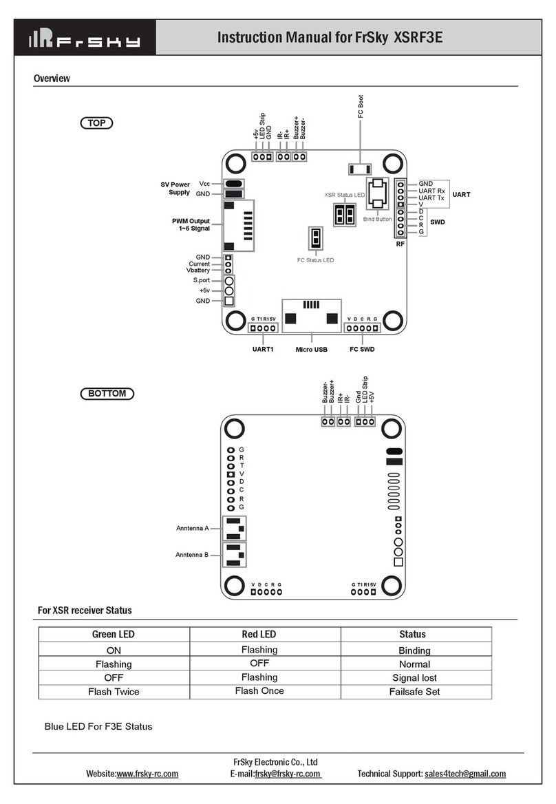
FrSky XSRF3E instruction manual
Becker
Becker Centronic SunWindControl SWC545-II Assembly and operating instructions

Kinco
Kinco KS Series manual

AMALGAMATED INSTRUMENT
AMALGAMATED INSTRUMENT PM4-IVT Operation and instruction manual
Denso
Denso SMT7 instruction manual
