1 Introduction
1.1 General description
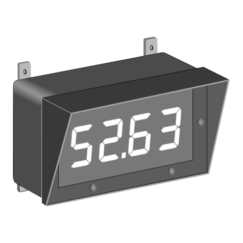
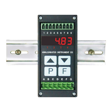
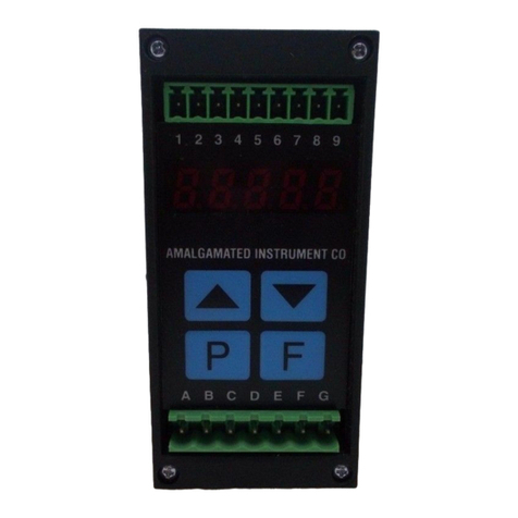
This manual contains information for the installation and operation of the PM4-IVT rate/total
monitor. The PM4-IVT is a general purpose instrument which may be configured to accept an
input signal of ±2mA, ±20mA, 4 to 20mA, ±100mV, ±1V, ±10V, ±100VDC or 3 wire slidewire
(0-1kΩ to 0-1MΩ).
The display can toggled between rate and total display via the ^or vpushbuttons or via a
remote switch input. The total can be reset by programming either the Pbutton (if fitted on
display type used) or the remote input (terminals 7 and 8) to clear the total, see P.but and R.INP
functions. Alternatively the total can be reset at the CLr totI function. Unless the display
has been programmed to automatically reset to zero (see totI RAP.F function) at full display
scale reading e.g. 99999 the display will show the message -or- when the total is too large to
display, when this message is seen the total will need to be reset before totalising operations can
be resumed. The instrument may be calibrated to display the input in engineering units.
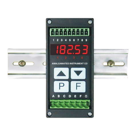
The PM4 series of Panel Mount Monitors are designed for high reliability in industrial applica-
tions. The high brightness LED display provides good visibility even in areas with high ambient
light levels. The high contrast LCD displays provide good visibility and are ideal for battery
powered applications. Full electrical isolation between power supply, input voltage or current and
retransmission output is provided by the PM4, thereby eliminating grounding and common voltage
problems. This isolation feature makes the PM4 ideal for interfacing to computers, PLCs and
other data acquisition devices. Unless otherwise specified at the time of order, your PM4 has been
factory set to a standard configuration. The PM4 series instruments can be configuration and
calibrated easily by the user. Initial changes may require dismantling the instrument to alter PCB
links, other changes are made by push button functions.
1.2 Standard outputs
•A standard inbuilt relay provides an alarm or on/off control function.
•A non isolated transmitter supply of approx. 18VDC (25mA max.) regulated is provided.
1.3 Output options
•1, 3 or 6 extra relays
•Isolated analog retransmission (single or dual analog outputs) configurable for 4–20mA, 0–1V
or 0–10V, configurable for retransmission or PI control
• ±12VDC (24V) isolated transmitter supply/excitation voltage (25mA max.). Not to be used
at the same time as the standard 18VDC unregulated transmitter supply
•Isolated RS485 or RS232 serial communications (ASCII or Modbus RTU)
•Isolated Digital output - binary or BCD up to 16 bit, NPN or PNP output types available
•Isolated Optional outputs are available in certain combinations e.g. Extra relay plus RS232
PM4IVTMAN-2.3-0 3 of 45
