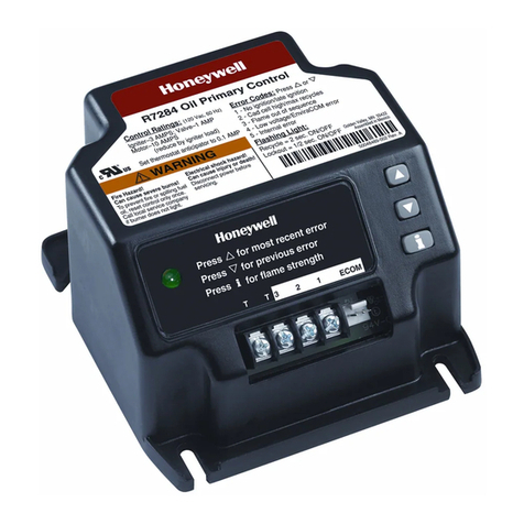
Chore-Time ATF 42343 User manual

Model ATF End Control with Sensor Plus
1. Attach one Swinging Pan Support (item 4) and three regular Pan Supports (item 2) to Pan Shield (item 3) using
rivets supplied. Always attach the Swinging Pan Support (item 4) at the same location on all Pan Shields (item
3). It will be necessary to support the Pan Shield (item 3) while installing the rivets. Use a hammer to drive
rivets as shown in Figure 1.
Figure 1. Assembling the Pan Supports to the Pan Shield
2. Install the Sensor Switch Assembly (item 1) to the Drop Tube (item 3) using the included #8 Hex Washer Head
Screw (item 2).
Figure 2. Installing the Sensor Switch Assembly to the Drop Tube
3. Install the Drop Tube Assembly (item 2) to the Pan Shield Assembly (item 1) by routing the Drop Tube
Assembly (item 2) up through the center of Pan Shield Assembly (item 1). Make sure the cord from the Sensor
Switch Assembly passes through the hole in the side of the Pan Shield Assembly (item 1).
Figure 3. Assembling the Drop Tube to the Pan Shield Assembly
Model ATF™ End Control with Sensor Plus™
Part Number 42343
and
Model ATF End Control Update Kit
Part Number 43711
1630-11 11/99
2
1
3
4
Item Description
1 Wood Block
2 Pan Support
3 Pan Shield
4 Swinging Pan Support
1630-2 11/99
1
1
2
3
Item Description
1 Sensor Switch Assembly
2 #8 Hex Washer Head Screw
3 Drop Tube
2
1
1630-3 11/99
Item Description
1 Pan Shield Assembly
2 Drop Tube Assembly
MF1630BDecember 2000

2
Model ATF™End Control with Sensor Plus™
MF1630B
4. Assemble the ATF End Control Body (item 1) to the Drop Tube with Pan Shield (item 2) by sliding the
ATF End Control Body (item 1) into the top of the Drop Tube with Pan Shield (item 2).
Figure 4. Assembling the ATF End Control to the Drop Tube Assembly
5. Secure the ATF End Control Body (item 2) to the Drop Tube Assembly using the included 1/4-20 Hex
Head Bolts (item 1).
Figure 5. Securing the ATF End Control Body
6. Route the Sensor Switch Assembly Cord up through the black Water Tight Connector on the bottom of
the Relay Box (item 1). Tighten the Water Tight Connector around the Sensor Switch Assembly Cord
making sure there is enough cord inside the Relay Box (item 1) to plug into the Socket on the Circuit
Board. Mount the Relay Box to the side of the ATF End Control Body (item 3) and secure using the
included #10-32 Hex Lock Nuts (item 2).
Figure 6. Installing the Relay Box to the ATF End Control Body
1630-4 11/99
2
1
Item Description
1 ATF End Control Body
2 Drop Tube with Pan Shield
1630-5 11/99
1
2
Item Description
1 1/4-20 Hex Head Bolts
2 ATF End Control Body
1630-6 11/99
1
3
2
Item Description
1 Relay Box
2 #10-32 Hex Lock Nuts
3 ATF End Control Body

Model ATF™End Control with Sensor Plus™
3
MF1630B
7. Install the Anchor Plate (item 2) to the Drive Unit (item 1) using the included 1/4-20 Hex Head Bolts
(item 3).
Figure 7. Installing the Anchor Plate to the Drive Unit
8. Connect the Plug (item 8) from the Sensor Switch Assembly into the Socket (item 7) on the Circuit
Board (item 9). See Figure 8.
Install the Pan Shield Assembly onto the Feeder Pan (item 6) by hooking the Swing Down Pan Support
through the hole in the Feeder Pan (item 6). Install the Feed Level Tube (item 4) and the Feed Level
Ring (item 5) then swing the pan upand snap the remaining Pan Supports over the lipof the Feeder Pan
(item 6). See Figure 8.
Important Do not bend the Pan Supports during assembly.
Install the Drive Unit and Anchor Plate (item 1) to the ATF End Control Body (item 3) using the
included 1/4-20 Hex Head Bolts (item 2). See Figure 8.
Figure 8. Assembling the components
1630-7 11/99
123Item Description
1DriveUnit
2 Anchor Plate
3 1/4-20 Hex Head Bolts
1630-8 8/2000
2
12
3
7
8
9
6
4 5
Item Description
1 Drive Unit and Anchor Plate
2 1/4-20 Hex Head Bolt
3 ATF End Control Body
4 Feed Level Tube
5 Feed Level Ring
6 Feeder Pan
7Socket
8Plug
9 Circuit Board with Heater

4
Model ATF™End Control with Sensor Plus™
MF1630B
9. Install the 90° Metal Conduit Connector (item 1) to the Motor (item 3). Cut the Flex Conduit (item 2)
to length and assemble with the 90° Metal Conduit Connector (item 1). Route the three wires through
the Flex Conduit (item 2) into the Motor (item 3) and assemble the Flex Conduit (item 2) with the
Conduit Connector (item 4) at the Relay Box (item 5). Wire the Motor (item 3) in accordance with the
motor plate.
Figure 9. Wiring the ATF End Control
10. Install the Metal Water Tight Connector (item 1) in the Feed Line Motor (item 2). Cut the Flex Conduit
(item 3) to length. Slide the wires from the end control through the Flex Conduit (item 3). Install the
Flex Conduit (item 3) in the connectors. Connect the wires to the Feed Line Motor (item 2).
Figure 4. Wiring the Motor
Item Description Part No. Item Description Part No.
1Metal Water Tight Connector 23810 7Product Identification Decal 2529-734
2Feed Line Motor ——— 8 Body Cover 27942
3Flexible Conduit 26982-1 9Bottom Plate 27893
4Water Tight Connector 26980 10 White Wire ———
5Safety Cover Assembly 27941 11 Black Wire ———
6Cord Assembly 4999-100 12 Green Wire ———
1630-9 11/99
1
3
2
45
Item Description
1 90° Metal Conduit Connector
2 Flex Conduit
3Motor
4 Conduit Connector
5RelayBox
DANGER
!
Do not open this control box
until electrical power is
disconnected at circuit
breakers.
1630-14 8/2000
11
12
10
12346
9
78
5

Model ATF™End Control with Sensor Plus™
5
MF1630B
Model ATF End Control Update Kit
The Model ATF End Control Update Kit is designed to replace an existing mechanical switch with a Sensor
Plus switch.
1. Disconnect the power at the circuit breaker. Remove and discard the Power Cord (item 6), 90°Romex
Connector (item 1) on the Motor, Motor Wires (item 3), Flex Conduit (item 2), Switch Box (item 4),
and Switch Box Mounting Plate (item 5).
Figure ?. Removing parts that will be replaced
2. Swing the Feeder Pan (item 5) down out of the way and remove the Drop Tube Assembly (item 3),
Feed Level Tube (item 1), and Feed Level Ring (item 2). Remove and discard the Switch Assembly
(item 4).
Figure ?. Removing the Switch Assembly
3. Reassemble following the instructions for the Model ATF End Control with Sensor Plus.
HAZARD
ELECTROCUTION
Donot open thiscon-
trolb oxu ntilelectrical
poweris disconnected
at circuitbreakers.
2527- 25
12
4
6
3
5
MF1630-12 8/2000
Item Description
190°Romex Connector
2 Flex Conduit
3 Motor Wires
4SwitchBox
5 Switch Box Mounting Plate
6PowerCord
MF1630-13 8/2000
1
2
3
5
4
Item Description
1 Feed Level Tube
2 Feed Level Ring
3 Drop Tube Assembly
4 Switch Assembly
5 Feeder Pan

6
Model ATF™End Control with Sensor Plus™
MF1630B
Switch Adjustment
The SENSOR PLUS Pan Half Round Sensor Switch is adjusted at the factory to a sensitivity of .25'' [6 mm]
and a time delay of 15 seconds, but they may be changed for a specific installation. The sensitivity
adjustment range is 0'' to .80'' [0 mm to 15 mm] and the time delay adjustment is 0 seconds to 600 seconds.
To adjust the Sensitivity:
•For less sensitivity —turn Sensitivity Adjusting Screw (item 4) clockwise
•For more sensitivity —turn Sensitivity Adjusting Screw (item 4) counter-clockwise
To adjust the Time Delay:
•For less time —turn Time Delay Adjusting Screw (item 5) clockwise (Light blinks fast)
•For more time —turn Time Delay Adjusting Screw (item 5) counter-clockwise (Light blinks slow)
Figure 2. Adjusting the SENSOR PLUS Proximity Switch
Internal Wiring
Control Wiring Diagram
1629-11 5/2000
3
0-15 mm
1-600 SEC
0$; 0,1
0$; 0,1
1
24
5
6
Item Description Part No.
1 Proximity Switch Cord ———
2 Switch Box 42627-3
3 Circuit Board with Heater 42604
4 Sensitivity Adjusting Screw ———
5 Time Delay Adjusting Screw ———
6Light ———
—Proximity Sensor Switch and
Circuit Board 44915
—Rectangle Sensor with Heater 42593
NCNO
COM
GREEN
GREEN
BLACK
WHITE
BLACK
WHITE
BLACK
WHITE
MPLUG FROM
SENSOR SWITCH
1630-16 8/2000
bb 9751
WHITE
230 V
60 HZ, 1 PH
SUPPLY 1
Item Description Part No.
1 Rectangle Sensor
with Heater 42593
End
Control
L1
L2
Ground
3 Wire Hook Up (Typical)
Ground
L1
L2
1634-07 5/2000
2529-710
!"
'$1*(5
! "
'$1*(5
Intermediate
Control
Shown with
3259-84
Power Unit
Bypass Switch
(not supplied)
230 VAC
Supply
60 HZ
Green
Black
White
Red
Black
White
White Black
Red

Model ATF™End Control with Sensor Plus™
7
MF1630B
Parts Listing
Model ATF End Control with Sensor Plus
*These items may be ordered as a Level Sensor Assembly, Part Number 44920.
Item Description Part No. Item Description Part No.
1Feed Level Tube 4341 17 Danger/Product Identification Decal 2529-734
2Control Body 27889 18 Electrical Box 42627-4
3Safety Cover Assembly 27941 19 1/2'' Conduit Connector 26980
4Anti Roost Guard 2798 20 Mounting Cover 6956
5Body Cover 27942 21 Switch Box Gasket 6777
6Stub Tube Weldment 27900 22 Switch Box Cover 6776
790°Metal Conduit Connector 23810 23 Swing Down Pan Support 24274
81/2'' Flexible Conduit 26982-1 24 Drive Rivet 4200
91/2'' Water Tight Connector 24685 25 Tube Support 24891
10 Cord Assembly 4999-100 26 Bottom Plate 27893
11* Proximity Switch Circuit Board 42604 27 Pan Shield 4191
12 1/2'' Conduit Lock Nut 43662 28 Pan Support 4199
13 1/2'' Water Tight Connector 23779 29 Guard Assembly 4892
14 Plastic Adapter Plate 43819 30 ATF Plastic Feeder Pan 29000
15 Adapter Plate 43813 31 Drop Tube Weldment 4180
16* Proximity Switch Sensor 42593 32 Feed Level Ring 29320
#$% & ' "
(&)##*+,*- -...
'$1*(5
!
Do notopen thiscontrol box
until electrical power is
disconnected at circuit
breakers.
4
1
32
31
78
19
20
18
21
22
15
16
17
14
12
13
11
9
10
35
6
25
26
27
23
29
30
2
28
1630-15 8/2000
24

8
Model ATF™End Control with Sensor Plus™
MF1630B
Model ATF End Control Update Kit Part Number 43711
*These items may be ordered as a Level Sensor Assembly, Part Number 44920.
Item Description Part No. Item Description Part No.
190°Metal Conduit Connector 23810 9Electrical Box 42627-4
21/2'' Flexible Conduit 26982-1 10 1/2'' Water Tight Connector 23779
31/2'' Water Tight Connector 24685 11 Adapter Plate 43813
4Cord Assembly 4999-100 12* Rectangle Sensor with Heater 42593
5Box Cover 6776 13 Cover Decal 2529-734
6Gasket 6777 14 Plastic Adapter Plate 43819
7Mounting Cover 6956 15 1/2'' Conduit Lock Nut 43662
81/2'' Conduit Connector 26980 16* Circuit Board with Heater 42604
1630-10 11/99
123
4
10 15
10
14
11
12
13
8
7
9
16
6
5
Chore-Time Equipment a Division of CTB Inc.
P.O. Box 2000 •Milford, Indiana 46542-2000 •U.S.A.
Phone (219) 658-4101 •Fax (877) 730-8825
E-Mail: ctb@ctbinc.com •Internet: http//www.ctbinc.com
This manual suits for next models
1
Table of contents
Other Chore-Time Control Unit manuals
Chore-Time
Chore-Time Chore-Tronics 2 User manual

Chore-Time
Chore-Time 108 FLEX-AUGER User manual
Chore-Time
Chore-Time PDS Control 4 Setup guide
Chore-Time
Chore-Time Tronics 3 User manual
Chore-Time
Chore-Time Chore-Tronics Model 8 Instruction Manual
Chore-Time
Chore-Time Chore-Tronics Natural Ventilation Instruction Manual
Popular Control Unit manuals by other brands

SIGLENT
SIGLENT STB3 user manual
Nelson
Nelson 800 Series quick start guide
Technische Alternative
Technische Alternative ESR 31 Operation & installation instructions

Kunbus
Kunbus PR100023R03 user manual

Power integrations
Power integrations Scale-2 1SC0450E2B0 Applications manual
Klark Teknik
Klark Teknik QFLEX ISOLATOR quick start guide
