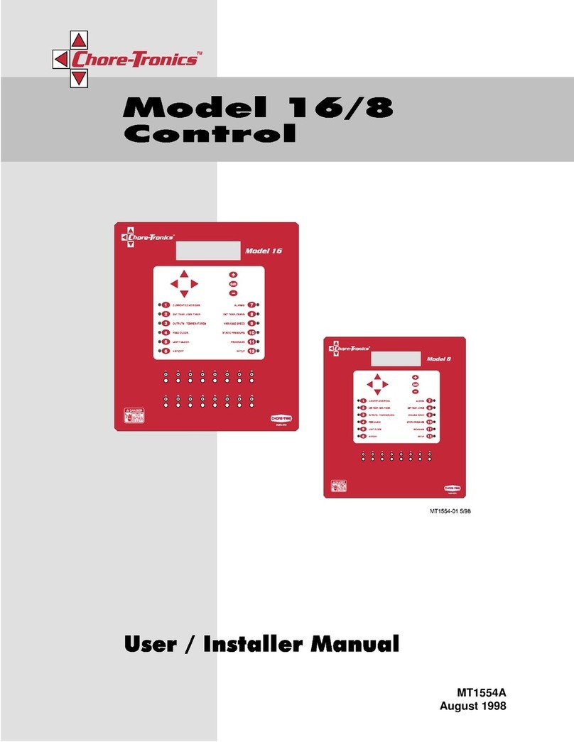
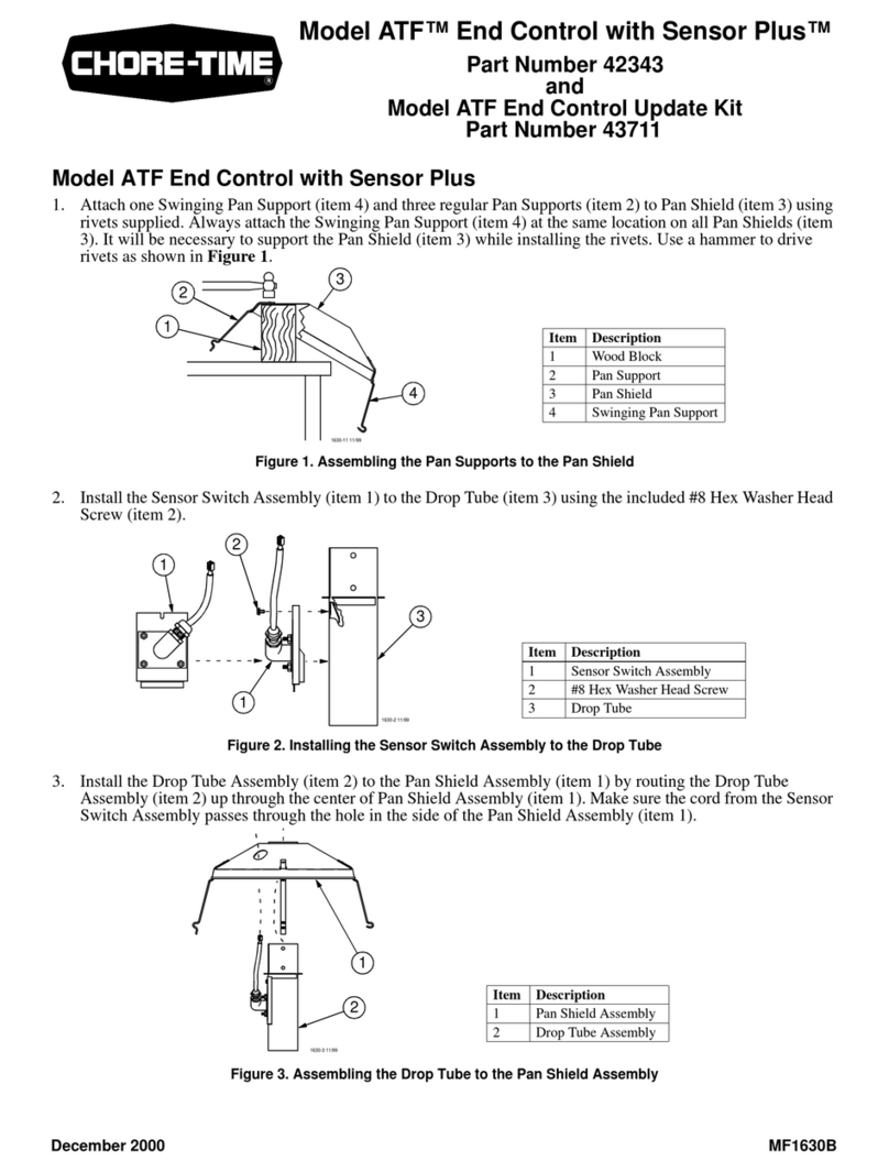
Chore-Time Tronics 3 User manual

Chore-Tronics®3 Breeder Edition Control
For additional parts and information, contact your nearest Chore-Time distributor or representative.
Find your nearest distributor at: www.choretime.com/contacts
MT2484ASeptember 2021
Installation and Operators Manual

Chore-Time Limited Warranty Chore-Tronics® 3 Breeder Edition Control
2MT2484A
CTB, Inc. (“Chore-Time”) warrants new CHORE-TRONICS®Controls manufactured by Chore-Time to be free from defects
in material or workmanship under normal usage and conditions, for One (1) year from the date of installation by the original
purchaser (“Warranty”). If such a defect is determined by Chore-Time to exist within the applicable period, Chore-Time will,
at its option, (a) repair the Product or Component Part free of charge, F.O.B. the factory of manufacture or (b) replace the
Product or Component Part free of charge, F.O.B. the factory of manufacture. This Warranty is not transferable, and applies
only to the original purchaser of the Product.
CONDITIONS AND LIMITATIONS. THIS WARRANTY CONSTITUTES CHORE-TIME’S ENTIRE AND
SOLE WARRANTY AND CHORE-TIME EXPRESSLY DISCLAIMS ANY AND ALL OTHER WARRANTIES,
INCLUDING, BUT NOT LIMITED TO, EXPRESS AND IMPLIED WARRANTIES, INCLUDING, WITHOUT
LIMITATION, WARRANTIES AS TO MERCHANTABILITY OR FITNESS FOR PARTICULAR PURPOSES. CHORE-
TIME shall not be liable for any direct, indirect, incidental, consequential or special damages which any purchaser may suffer
or claim to suffer as a result of any defect in the Product. Consequential or Special Damages as used herein include, but are
not limited to, lost or damaged products or goods, costs of transportation, lost sales, lost orders, lost income, increased
overhead, labor and incidental costs, and operational inefficiencies. Some jurisdictions prohibit limitations on implied
warranties and/or the exclusion or limitation of such damages, so these limitations and exclusions may not apply to you. This
warranty gives the original purchaser specific legal rights. You may also have other rights based upon your specific
jurisdiction.
Compliance with federal, state and local rules which apply to the location, installation and use of the Product are the
responsibility of the original purchaser, and CHORE-TIME shall not be liable for any damages which may result from non-
compliance with such rules.
The following circumstances shall render this Warranty void:
· Modifications made to the Product not specifically delineated in the Product manual.
· Product not installed and/or operated in accordance with the instructions published by the CHORE-TIME.
· All components of the Product are not original equipment supplied by CHORE-TIME.
· Product was not purchased from and/or installed by a CHORE-TIME authorized distributor or certified
representative.
· Product experienced malfunction or failure resulting from misuse, abuse, mismanagement, negligence, alteration,
accident, or lack of proper maintenance, or from lightning strikes, electrical power surges or interruption of
electricity.
· Product experienced corrosion, material deterioration and/or equipment malfunction caused by or consistent with the
application of chemicals, minerals, sediments or other foreign elements.
· Product was used for any purpose other than for the care of poultry and livestock.
The Warranty may only be modified in writing by an officer of CHORE-TIME. CHORE-TIME shall have no obligation or
responsibility for any representations or warranties made by or on behalf of any distributor, dealer, agent or certified
representative.
Effective: April, 2014
Chore-Time Limited Warranty

Contents
Topic Page
MT2484A 3
Chore-Time Limited Warranty. . . . . . . . . . . . . . . . . . . . . . . . . . . . . . . . . . . . . . . . . . . . . . . . . . . . . 2
General. . . . . . . . . . . . . . . . . . . . . . . . . . . . . . . . . . . . . . . . . . . . . . . . . . . . . . . . . . . . . . . . . . . . . . . . . 5
Support Information . . . . . . . . . . . . . . . . . . . . . . . . . . . . . . . . . . . . . . . . . . . . . . . . . . . . . . . . . . . . . . . . . . . 5
Safety Information . . . . . . . . . . . . . . . . . . . . . . . . . . . . . . . . . . . . . . . . . . . . . . . . . . . . . . . . . . . . . . . 5
Follow Safety Instructions . . . . . . . . . . . . . . . . . . . . . . . . . . . . . . . . . . . . . . . . . . . . . . . . . . . . . . . . . . . . . . 5
Decal Descriptions . . . . . . . . . . . . . . . . . . . . . . . . . . . . . . . . . . . . . . . . . . . . . . . . . . . . . . . . . . . . . . . . . . . . 5
DANGER: Electrical Hazard . . . . . . . . . . . . . . . . . . . . . . . . . . . . . . . . . . . . . . . . . . . . . . . . . . . . . . . . 5
Control Setup . . . . . . . . . . . . . . . . . . . . . . . . . . . . . . . . . . . . . . . . . . . . . . . . . . . . . . . . . . . . . . . . . . . 6
Analog Inputs . . . . . . . . . . . . . . . . . . . . . . . . . . . . . . . . . . . . . . . . . . . . . . . . . . . . . . . . . . . . . . . . . . . . . . . . 6
Egg Room Relative Humidity Sensor . . . . . . . . . . . . . . . . . . . . . . . . . . . . . . . . . . . . . . . . . . . . . . . . . . 6
Egg Room Temperature Sensor. . . . . . . . . . . . . . . . . . . . . . . . . . . . . . . . . . . . . . . . . . . . . . . . . . . . . . . 7
Temperature Sensor Analog Input Assignment. . . . . . . . . . . . . . . . . . . . . . . . . . . . . . . . . . . . . . . . . . . 7
Feed Bin Load Cells . . . . . . . . . . . . . . . . . . . . . . . . . . . . . . . . . . . . . . . . . . . . . . . . . . . . . . . . . . . . . . . 8
BinTrac to Chore-Tronics Control Calibration. . . . . . . . . . . . . . . . . . . . . . . . . . . . . . . . . . . . . . . . . . . . . . . 9
BinTrac Load Cell Calibration . . . . . . . . . . . . . . . . . . . . . . . . . . . . . . . . . . . . . . . . . . . . . . . . . . . . . . . 9
Calibrating the Chore-Tronics Control . . . . . . . . . . . . . . . . . . . . . . . . . . . . . . . . . . . . . . . . . . . . . . . . .10
Chore-Time Load Cells . . . . . . . . . . . . . . . . . . . . . . . . . . . . . . . . . . . . . . . . . . . . . . . . . . . . . . . . . . . . .11
Calibration . . . . . . . . . . . . . . . . . . . . . . . . . . . . . . . . . . . . . . . . . . . . . . . . . . . . . . . . . . . . . . . . . . . . . . .11
Digital Inputs . . . . . . . . . . . . . . . . . . . . . . . . . . . . . . . . . . . . . . . . . . . . . . . . . . . . . . . . . . . . . . . . . . . . . . . .12
Feed Scale Wiring (Dump Scale) . . . . . . . . . . . . . . . . . . . . . . . . . . . . . . . . . . . . . . . . . . . . . . . . . . . . .12
Mechanical Scale . . . . . . . . . . . . . . . . . . . . . . . . . . . . . . . . . . . . . . . . . . . . . . . . . . . . . . . . . . . . . . . . . .13
Egg Counters . . . . . . . . . . . . . . . . . . . . . . . . . . . . . . . . . . . . . . . . . . . . . . . . . . . . . . . . . . . . . . . . . . . . .14
Outputs . . . . . . . . . . . . . . . . . . . . . . . . . . . . . . . . . . . . . . . . . . . . . . . . . . . . . . . . . . . . . . . . . . . . . . . . . . . . .15
Clocks Tab. . . . . . . . . . . . . . . . . . . . . . . . . . . . . . . . . . . . . . . . . . . . . . . . . . . . . . . . . . . . . . . . . . . . . . .15
Note: Four output relays can be assigned to each Clock. . . . . . . . . . . . . . . . . . . . . . . . . . . . . . . . . . . .15
Feeding System (Matrix) . . . . . . . . . . . . . . . . . . . . . . . . . . . . . . . . . . . . . . . . . . . . . . . . . . . . . . . . . . . . . . .18
Feeding System Setup Examples. . . . . . . . . . . . . . . . . . . . . . . . . . . . . . . . . . . . . . . . . . . . . . . . . . . . . .18
Output Setup Egg Room (Relative Humidity and Temp) Cooler and Humidity . . . . . . . . . . . . . . . . .21
Clocks Setup . . . . . . . . . . . . . . . . . . . . . . . . . . . . . . . . . . . . . . . . . . . . . . . . . . . . . . . . . . . . . . . . . . . . .22
Management Screens . . . . . . . . . . . . . . . . . . . . . . . . . . . . . . . . . . . . . . . . . . . . . . . . . . . . . . . . . . . . . . . . . .26
Mortality . . . . . . . . . . . . . . . . . . . . . . . . . . . . . . . . . . . . . . . . . . . . . . . . . . . . . . . . . . . . . . . . . . . . . . . .26
Feed . . . . . . . . . . . . . . . . . . . . . . . . . . . . . . . . . . . . . . . . . . . . . . . . . . . . . . . . . . . . . . . . . . . . . . . . . . . .27
Inventory . . . . . . . . . . . . . . . . . . . . . . . . . . . . . . . . . . . . . . . . . . . . . . . . . . . . . . . . . . . . . . . . . . . . . . . .28
Egg. . . . . . . . . . . . . . . . . . . . . . . . . . . . . . . . . . . . . . . . . . . . . . . . . . . . . . . . . . . . . . . . . . . . . . . . . . . . .28
History Screens . . . . . . . . . . . . . . . . . . . . . . . . . . . . . . . . . . . . . . . . . . . . . . . . . . . . . . . . . . . . . . . . . . . . . . .30
Environment . . . . . . . . . . . . . . . . . . . . . . . . . . . . . . . . . . . . . . . . . . . . . . . . . . . . . . . . . . . . . . . . . . . . .30
Production . . . . . . . . . . . . . . . . . . . . . . . . . . . . . . . . . . . . . . . . . . . . . . . . . . . . . . . . . . . . . . . . . . . . . . .30
Wiring . . . . . . . . . . . . . . . . . . . . . . . . . . . . . . . . . . . . . . . . . . . . . . . . . . . . . . . . . . . . . . . . . . . . . . . . 32
BinTrac to Chore-Tronics Control Wiring . . . . . . . . . . . . . . . . . . . . . . . . . . . . . . . . . . . . . . . . . . . . . . . . . .32
Backup Egg Room Cooler Wiring . . . . . . . . . . . . . . . . . . . . . . . . . . . . . . . . . . . . . . . . . . . . . . . . . . . . . . . .33
Backup Egg Room Humidifier Wiring. . . . . . . . . . . . . . . . . . . . . . . . . . . . . . . . . . . . . . . . . . . . . . . . . . . . .33
Chore-Time Load Cell Wiring . . . . . . . . . . . . . . . . . . . . . . . . . . . . . . . . . . . . . . . . . . . . . . . . . . . . . . . . . . .34
Wiring to Chore-Tronics Control and Weighmatic Scale . . . . . . . . . . . . . . . . . . . . . . . . . . . . . . . . . . . . . .35
Relative Humidity Sensor (RH) Wiring . . . . . . . . . . . . . . . . . . . . . . . . . . . . . . . . . . . . . . . . . . . . . . . . . . . .36
Temperature Sensor Wiring . . . . . . . . . . . . . . . . . . . . . . . . . . . . . . . . . . . . . . . . . . . . . . . . . . . . . . . . . . . . .36
Alarms . . . . . . . . . . . . . . . . . . . . . . . . . . . . . . . . . . . . . . . . . . . . . . . . . . . . . . . . . . . . . . . . . . . . . . . . 37
Egg room Alarm . . . . . . . . . . . . . . . . . . . . . . . . . . . . . . . . . . . . . . . . . . . . . . . . . . . . . . . . . . . . . . . . . . . . . .37
Preset Not Met Alarm . . . . . . . . . . . . . . . . . . . . . . . . . . . . . . . . . . . . . . . . . . . . . . . . . . . . . . . . . . . . . . . . . .37
Current Conditions . . . . . . . . . . . . . . . . . . . . . . . . . . . . . . . . . . . . . . . . . . . . . . . . . . . . . . . . . . . . . . . . . . . .37
Todays Feed. . . . . . . . . . . . . . . . . . . . . . . . . . . . . . . . . . . . . . . . . . . . . . . . . . . . . . . . . . . . . . . . . . . . . .37

Contents - continued
Topic Page
4MT2484A
Special Functions . . . . . . . . . . . . . . . . . . . . . . . . . . . . . . . . . . . . . . . . . . . . . . . . . . . . . . . . . . . . . . . 38
Tunnel Fan at Feeding . . . . . . . . . . . . . . . . . . . . . . . . . . . . . . . . . . . . . . . . . . . . . . . . . . . . . . . . . . . . . . . . .38
Charts. . . . . . . . . . . . . . . . . . . . . . . . . . . . . . . . . . . . . . . . . . . . . . . . . . . . . . . . . . . . . . . . . . . . . . . . . 39

Chore-Tronics® 3 Breeder Edition Control General
MT2484A 5
Technical Specifications140Technical Specifications139
Support Information
This Manual is a to be used in addition to the Chore-Time Chore-Tronics®3 Control Installation Manual (MT2398)
to control the Climate in a structure to insure efficient growth of Livestock. Using this equipment for any other
purpose or in a way not within the operating recommendations specified in this manual will void the warranty and
may cause personal injury.
Caution, Warning and Danger Decals have been placed on the equipment to warn of potentially dangerous
situations. Care should be taken to keep this information intact and easy to read at all times. Replace missing or
damaged safety decals immediately.
Using the equipment for purposes other than specified in this manual may cause personal injury and/or damage to
the equipment.
Follow Safety Instructions
Carefully read all safety messages in this manual and on your equipment safety signs. Follow recommended
precautions and safe operating practices.
Keep safety signs in good condition. Replace missing or damaged safety signs.
Decal Descriptions
DANGER: Electrical Hazard
Disconnect electrical power before inspecting or servicing equipment unless maintenance instructions specifically
state otherwise.
Ground all electrical equipment for safety.
All electrical wiring must be done by a qualified electrician in accordance with local and national electric codes.
Ground all non-current carrying metal parts to guard against electrical shock.
With the exception of motor overload protection, electrical disconnects and over current protection are not supplied
with the equipment.
General
Safety Information

Control Setup Chore-Tronics® 3 Breeder Edition Control
6MT2484A
For the Following see the standard Chore-Tronic’s®3 Manual (MT2398).
•Temperature Sensors
•Static Pressure sensor (4-20 mA)
•Relative Humidity Sensor (0-10 volts)
•Potentiometer (Natural Ventilation)
Analog Inputs
Egg Room Relative Humidity Sensor
1.In the Setup/Analog/Type & Number screen check Egg Room Humidity.
2.See “Relative Humidity Sensor (RH) Wiring” on page 36.
1.Assign the Egg Room Relative Humidity Sensor to the Analog input you connected the sensor to.
Control Setup
2

Chore-Tronics® 3 Breeder Edition Control Control Setup
MT2484A 7
Egg Room Temperature Sensor
1.In the Setup/Analog/Type & Number screen check Egg Room Temperature.
2.See “Temperature Sensor Wiring” on page 36.
Temperature Sensor Analog Input Assignment
1.Assign the Egg Room Temperature Sensor to the Analog Input where you connected the Sensor.
1

Control Setup Chore-Tronics® 3 Breeder Edition Control
8MT2484A
Feed Bin Load Cells
1.In the Setup/Analog/Type & Number screen check Load Cell.
2.In the Setup/Analog Inputs select the Load Cell button.
3.From the Board dropdown menu select the device being used for the Load cell input (LCC or ILM).
Note: ILM is how the SJB is identified in the CT3 Control.
4.From the Input dropdown select the Analog input where the board is connected.
5.If a Bin Lid switch is used enter the Digital in.
6.Select the Control Tab and select the Bin Size from the dropdown.
3
4
5
6

Chore-Tronics® 3 Breeder Edition Control Control Setup
MT2484A 9
BinTrac to Chore-Tronics Control Calibration
For calibrating the HouseLink HL-10P/HL-10P(LV) with
Chore-Tronic's® 3 control, please refer to these instructions.
1.Install the load cell system per BinTrac’s Installation
Manual.
2.Connect the Chore-tronics®3 to BinTrac. See “BinTrac
to Chore-Tronics Control Wiring” on page 32.
3.Setup the analog input in the CT 3. From the drop in the
Board column select the device. The last number in the
device name is the address that you assigned to the ILM
(SJB).
BinTrac Load Cell Calibration
1.The BinTrac House Link HL-10P(LV) has four dip
switches that need to be set up for configuration.
2.The settings on the switches S1 and S2 coincide with the
bin: Set for Bin B.
3.Set S3 to the ON position to allow the ZERO to be tracked by the house controls.
4.Set S4 to the ON position to provide a 2mV/V at full scale instead.
5.Bin D must be enabled on the Bin Trac Indicator when BinTrac Monitor is connected to: BinTrac HouseLink
HL-10P/HL-10P(LV).
6.Refer to the BinTrac Installation and Operation Manual HouseLINK HL-10P & HL-10P(LV) on how to make
these settings.
7.Once the unit is wired and the dip switches are set up correctly, you can now start the Calibration.
8.Two people are needed for this procedure. One at the BinTrac HouseLINK HL-10P & HL-10P(LV) box and
one at the CT 3 control.
9.On the board of the HouseLINK HL-10P
& HL-10P(LV) there is a Test button that
will be used to send a Zero and Full bin
calibration number.
3
BinTrac HouseLink HL-10P
ON
123 42
Bin S1 S2 S3 S4
DOnOnOffOff
Bin S1 S2 S3 S4
A Off Off Off Off
Bin S1 S2 S3 S4
B On Off Off Off
ON
123 42
Bin S1 S2 S3 S4
C Off On Off Off
ON
123 42
ON
123 42
Bin-Trac Dip Switch Settings
9

Control Setup Chore-Tronics® 3 Breeder Edition Control
10 MT2484A
Calibrating the Chore-Tronics Control
Calibrate the Chore-Tronic's 3 control using the calibration screens for Zero and Full weight by using the
HouseLink HL-10P(LV) test mode to output an empty and full weight simulated weight reading.
1.Press the TEST button on the HouseLink HL-10P(LV) two times for the 0mV/V output setting which rep-
resents an empty bin weight reading. Zero
2.At the Chore-Tronic's 3 go to the Setup/Analog Inputs/Load Cell Screen and Select Calibrate. This will take
you to the Zero Calibration screen.
3.Make sure the calibration numbers are steady. Select OK. If the calibration is accepted the screen will change
to Weight Calibration of Scale screen.
4.At the HouseLink HL-10P(LV) press the TEST button one time for the 2mV/V output setting which represents
a full bin weight reading.
5.At the Chore-Tronic's 3 in the Weight Calibration Scale screen enter the capacity of the loadcells and the units
from the dropdown.
For Example, if four 5000lb. load cells are used, then the calibration weight will be 20,000 lbs.
See Figure 2. on page 39 for Calibration weight. Make sure the calibration numbers are steady.
6.Press OK.
7.Press TEST button on Houselink HL-10P(LV) three more times return to normal operation.
2
1
65
3

Chore-Tronics® 3 Breeder Edition Control Control Setup
MT2484A 11
Chore-Time Load Cells
1.Install the load cell system per the Load Cell installation manual.
2.Connect the CT 3 IO terminals to the SJB IO net terminals.
Calibration
1.Go to the Setup/Analog Inputs/Load Cell Screen and Select Calibrate.
2.With no feed in the Bin select the OK Button. If there is no error then continue.
3.At the Chore-Tronic's 3 in the Weight Calibration Scale screen enter the known weight in the Bin and the units
wanted from the dropdown. Example shows 500 lb.
3
2

Control Setup Chore-Tronics® 3 Breeder Edition Control
12 MT2484A
Digital Inputs
Feed Scale Wiring (Dump Scale)
1.In the Setup/digital Inputs/Type & numbers put a check in the Dump Scales box.
2.Use the Back arrow to go back to the Setup/Digital Inputs Screen and Select the Dump Scales button.
3.Enter the Digital Input that the dump scale switch is connected.
4.Enter the Board #,Input #, Name the Scale, Units per pulse and Units.
5.If one or more Feed Scales are used, they need to be connected to one of the Digital (DI) Inputs on the IO board
using Twisted Pair Wire. Connect the switch located on the side of the Feed Scale to the IO Board using the
blue and brown wires (See Figure 1.) See manual MT1811 for more information on the Dump Scale.
2
2 2 4
DI1
12V
Item Description
1 Feed Scale
2 I/O Board Digital Input (DI)
terminal of your Choice
2(DI) of your Choice
1
Figure 1.Feed Scale Wiring

Chore-Tronics® 3 Breeder Edition Control Control Setup
MT2484A 13
Mechanical Scale
1.In the Setup/Digital Inputs/Type & numbers Screen put a Check mark in the Mechanical Scale box.
2.Select the Mechanical Scale button.
3.From the drop-downs select the Board and Input.
4.The Status column shows if the switch is activated or not.
5.See Wiring Chore-Tronics Control and Weigh-matic Scale for wiring information.
3 3

Control Setup Chore-Tronics® 3 Breeder Edition Control
14 MT2484A
Egg Counters
1.In the Setup/Digital Inputs/Type & numbers Screen put a Check mark in the Egg Counter box.
2.Back up one Screen to the Setup/Digital Inputs Screen and select the Egg Counter Button.
3. From the drop-downs select the Board and Input.
4.You can Add or Remove Counters.
5.Up to five sets of Counters can be added. Each Set consists of two Counters and one Switch.
"Switch" is used to kept track of Run Times and to tell the CT 3 to start counting egg when the belts start.
Examples:
2
43
Example: House with Single Belt Collectors
(One Set of Counters)
Example: House with Two Double Belt Collectors
(Two Set of Counters)

Chore-Tronics® 3 Breeder Edition Control Control Setup
MT2484A 15
Outputs
In the CT 3 Breeder control the Setup/Outputs/Equipped & Numbers screen has been separated with four tabs.
Note: Equipped & Numbers screens must be completed before any Outputs are assigned.
Clocks Tab
Note: Four output relays can be assigned to each Clock.
Female Feed Clock
1.Go to the Setup/Outputs/Clock Screen and Select Female Feed.
2.Rename if needed. Assign Relays as needed.
3.Select the Control Tab.
4.A check in the (Disable All Female Feed Delivery At Max Runtime box) will turn off the Female Fill
when Feeder run time is met.
5.A check in the (Stop feed when preset is for box's) will turn off the Female feeder when the Preset
(current day feed total) is met.
Male Feed Clock
1.Follow the same steps to setup the Male Water Clock.
2
1
4
5
3

Control Setup Chore-Tronics® 3 Breeder Edition Control
16 MT2484A
Female Water Clock
In the Setup/Outputs/Clock/Female Water Screen...
1.Select the Relay or Relays from the drop-downs.
2.Rename if needed.
Male Water Clock
Set up for the Male Water Clock is the same as for the Female Water Clock.
Feeder Fill Clock
In the Setup/Outputs/Clock/Feeder Fill Screen enter....
1.The Relay or Relays from the dropdown.
2.Select the Scale type from the dropdown
3.Select the scale number from the dropdown
4.Rename if needed.
Note: Follow the same steps to setup all Feeder Fill Clocks. Caution! Do not allow Weigh Fill and Feeder
Fill Times to Overlap.
2
1
1
4
2
3

Chore-Tronics® 3 Breeder Edition Control Control Setup
MT2484A 17
Feed Winch Clock (Male Feeder Winch)
In the Setup/Outputs/Clock/Feed Winch Screen enter....
1.The Relay or Relays from the dropdown.
2.Rename if needed.
Light Clock, Spare Clock and PDS Clock
See the Chore-Tronics Manual to set up the Light, Spare and PDS Clocks.
1
2

Control Setup Chore-Tronics® 3 Breeder Edition Control
18 MT2484A
Feeding System (Matrix)
Note: The Feeding System Matrix has to be setup after all Clock Outputs have been assigned and all Clocks have
been setup. See “Clocks Setup” on page 22
The Feeding System Screen allows the user to setup six different Feeding Systems. Clocks that are to be used in a
specific Feeding System are entered in the Matrix.
Important! It is very important to assign both the Male/Female choice, as well as the line number in this Screen.
Failure to do so could cause Clocks to follow the wrong schedule.
Feeding System Setup Examples
The examples to follow show how the Clocks are assigned and how the Feeding System Matrix would be setup.
W
S
"S" Supply Bin
"W" Weigh Bin
S
Table of contents
Other Chore-Time Control Unit manuals

Chore-Time
Chore-Time PDS Control 4 Setup guide

Chore-Time
Chore-Time 108 FLEX-AUGER User manual

Chore-Time
Chore-Time Chore-Tronics Model 8 Instruction Manual

Chore-Time
Chore-Time Chore-Tronics Natural Ventilation Instruction Manual

Chore-Time
Chore-Time ATF 42343 User manual

Chore-Time
Chore-Time Chore-Tronics 2 User manual