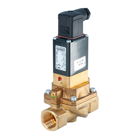
Burkert 6440 User manual

Type 6440
2/2-way solenoid valve, servo-assisted
Operating Instructions

We reserve the right to make technical changes without notice.
© Bürkert Werke GmbH & Co. KG, 2023
Operating Instructions 2306/00_ENen_ 00815439 / Original DE

Type 6440
Contents
3
CONTENTS
1 About this document..................................................................................................................................4
1.1 Manufacturer .................................................................................................................................... 4
1.2 Used symbols................................................................................................................................... 4
1.3 Terms and abbreviations .................................................................................................................. 5
2 Safety instructions......................................................................................................................................6
2.1 Intended use..................................................................................................................................... 6
2.2 Safety................................................................................................................................................ 6
3 Product description....................................................................................................................................9
3.1 Product structure.............................................................................................................................. 9
3.2 Type label ....................................................................................................................................... 10
4 Technical data ..........................................................................................................................................11
4.1 Standards and Directives ............................................................................................................... 11
4.2 Operating conditions ...................................................................................................................... 11
4.3 Circuit function ............................................................................................................................... 12
5 Installation ................................................................................................................................................13
5.1 Preparatory work ............................................................................................................................ 13
5.2 Installation of socket variants ......................................................................................................... 13
5.3 Installation of cartridge variants ..................................................................................................... 14
5.4 Flange variant installation ............................................................................................................... 16
5.5 Coil installation ............................................................................................................................... 17
5.6 Cable plug installation .................................................................................................................... 18
6 Electrical connection................................................................................................................................19
6.1 Cable plug Type 2518, plug shape A according to DIN EN175301-803....................................... 19
6.2 Automotive plugs for IP6K9K coil variants ..................................................................................... 20
7 Faults ........................................................................................................................................................21
8 Logistics....................................................................................................................................................22
8.1 Transport and storage .................................................................................................................... 22
8.2 Disposal .......................................................................................................................................... 22

Type 6440
About this document
4
1 ABOUT THIS DOCUMENT
The document is an important part of the product and guides the user to safe installation and operation.
The information and instructions in this document are binding for the use of the product.
Before using the product for the first time, read and observe the whole safety chapter.
Before starting any work on the product, read and observe the respective sections of the document.
Keep the document available for reference and give it to the next user.
Contact the Bürkert sales office for any questions.
Further information concerning the product at country.burkert.com.
1.1 Manufacturer
Bürkert Fluid Control Systems
Christian-Bürkert-Str. 13−17
D-74653 Ingelfingen
The contact addresses are available at country.burkert.com in the menu Contact.
1.2 Used symbols
DANGER!
Warns of a danger that leads to death or serious injuries.
WARNING!
Warns of a danger that can lead to death or serious injuries.
CAUTION!
Warns of a danger that can lead to minor injuries.
NOTICE!
Warns of property damage that can damage the product or the installation.
Indicates important additional information, tips and recommendations.
Refers to information in this document or in other documents.
Indicates a step to be carried out.
Indicates a result.
Menu Indicates a software user-interface text.

Type 6440
About this document
5
1.3 Terms and abbreviations
The terms and abbreviations are used in this document to refer to following definitions.
Device 2/2-way solenoid valve; servo-assisted, type 6440
bar Unit for relative pressure

Type 6440
Safety instructions
6
2 SAFETY INSTRUCTIONS
2.1 Intended use
The device is designed to control the flow rate of media. The permitted media are listed in Technical
data [}11].
Prerequisites for safe and trouble-free operation are correct proper transportation, storage, installation,
start-up, operation and maintenance.
The instructions are part of the device. The device is intended exclusively for use within the scope of these
instructions. Uses of the device that are not described in these instructions, the contractual documents or
the type label can lead to severe personal injury or death, damage to the device or property and dangers for
the surrounding area or the environment.
Do not mechanically load the device.
Only trained and qualified personnel may install, operate and maintain the device. See qualification of
persons in Safety [}6]
Use the device only in conjunction with third-party devices and components recommended and author-
ized by Bürkert.
Use the device only when it is in perfect condition.
2.2 Safety
Qualification of personnel working with the device
Improper use of the device can lead to serious personal injury or death. To avoid accidents when working
with the device, the following minimum requirements must be met:
Carry out work on the device within the scope of these instructions in a safety-compliant manner.
Detect and avoid dangers when working on the device.
Understand the instructions and implement the information contained therein accordingly.
Responsibility of the operator
The operator is responsible for observing the location-specific safety regulations, also in relation to person-
nel.
Observe the general rules of technology.
Install the device according to the regulations applicable in the respective country.
The operator must make hazards arising from the location of the device avoidable by providing appropri-
ate operating instructions.
Only use authorised devices in a potentially explosive atmosphere
There are variants for this device type that may be used in Ex areas. These variants are identified by a sep-
arate Ex type label. The scope of delivery for these variants includes additional instructions identified with
the ATEX logo.
Only use devices that are approved for this type of potentially explosive atmosphere.
Note the information on the separate Ex type label for usage in an Ex area.
Follow the additional instructions identified with the ATEX logo for usage in an Ex area.

Type 6440
Safety instructions
7
Changes and other modifications, spare parts and accessories
Changes to the device, incorrect installation or use of non-approved devices or components create hazards
that can lead to accidents and injuries.
Do not make any changes to the device.
Do not mechanically load the device.
Observe the operating instructions of the device or component used.
Only use the devices in conjunction with approved devices or components.
Spare parts and accessories that do not meet Bürkert’s requirements may impair the operational safety of
the device and cause accidents.
To ensure operational safety, only use original parts from Bürkert.
Operation only after proper transport, storage, installation, start-up or maintenance.
Improper transport, storage, installation, start-up or maintenance endanger the operational safety of the
device and can cause accidents. This can lead to serious personal injury or death.
Only carry out works which are described in these instructions.
Only carry out works using suitable tools.
Have all other works carried out by Bürkert only.
Technical limit values and media
Non-compliance with technical limit values or unsuitable media can damage the device and lead to leaks.
This can cause accidents and seriously injure or kill people.
Comply with limit values. See Technical data [}11] and information on the type label.
Only feed media into the media ports that are listed in the chapter Technical data [}11].
Observe the safety data sheet for the media used.
Medium under pressure
Medium under pressure can seriously injure people. In the event of overpressure or pressure surges, the
device or lines can burst. Pneumatic lines that are defective or not securely fastened can come loose and
swing around.
Before working on the device or system, switch off the pressure. Vent or empty the lines.
Adhere to the permitted pressure ranges of the medium.
Comply with the permitted temperature ranges of the medium.
Electric shock due to electrical components
Touching live parts can result in severe electric shock. This can lead to serious personal injury or death.
Before working on the device or system, switch off the power supply. Secure it against reactivation.
Observe any applicable accident prevention and safety regulations for electrical devices.
Hot surfaces and fire hazard
The surface of the device can become hot with fast-switching actuators or with hot media.
Wear suitable protective gloves.
Keep highly flammable substances and media away from the device.

Type 6440
Safety instructions
8
Working on the device
Working on the device that has not been powered down, unauthorised switching on or uncontrolled start-
up of the system can cause accidents. This can lead to serious personal injury or death.
Only work on the device when it is not in use.
Ensure that the device or system cannot be switched on unintentionally.
Only start the process in a controlled manner following disruptions. Observe sequence:
1. Apply supply voltage or pneumatic supply.
2. Charge the device with medium.

Type 6440
Product description
9
3 PRODUCT DESCRIPTION
Type 6440 is a pilot-operated and compact 2/2-way piston valve with the following properties:
Safe opening via a force pilot operated piston system.
Vibration-proof, screwed coil system
Increased leak proofing through welded core guide tube.
Optimised for use in hydrogen applications, such as fuel cells or electrolysis.
3.1 Product structure
1
2
3
4
Fig.1: Type 6440 socket variants
1 Coil 2 Valve body
3 Type label 4 Nut for coil attachment
2
3
4
51
Fig.2: Typ 6440 flange variant FK14/FK17
1 Coil 2 4 M4 screws (variant FK14) or M5 screws
(variant FK17)
3 Valve body 4 Type label
5 Nut for coil attachment

Type 6440
Product description
10
2
3
5
1
6
4
Fig.3: Type 6440 cartridge variant FC16/FC17
1 Coil 2 2 M6 screws (variant FC16) or 4 M5 screws
(variant FC17)
3 Retaining plate 4 Valve body
5 Type label 6 Nut for coil attachment
3.2 Type label
1 2 3 4 5
14 6
13 7
8
9
10
11
12
Fig.4: Type label Type 6440 (example)
1 Type 2 Circuit function
3 Orifice 4 Sealing material
5 Body material 6 Operating pressure
7 Cold power (tolerance ±10%) 8 Ambient temperature
9 CE marking 10 Manufacture code
11 Article number 12 Indication for disposal
13 Operating voltage 14 Port connection

Type 6440
Technical data
11
4 TECHNICAL DATA
4.1 Standards and Directives
The device complies with the relevant EU harmonisation legislation. In addition, the device also complies
with the requirements of the laws of the United Kingdom.
The harmonised standards that have been applied for the conformity assessment procedure are listed in
the current version of the EU Declaration of Conformity/UK Declaration of Conformity.
4.2 Operating conditions
Medium neutral gases and liquids, optimised for hydrogen
Medium temperature −40 °C...+120 °C
Ambient temperature -40°C...+55°C/+75°C for stationary applications
- 40°C…+ 85°C for mobile applications
Storage temperature −40°C...+80°C
Operating mode Unless otherwise specified on the type label, the solenoid actuator is
suitable for continuous operation.
For mobile applications with a higher ambient temperature (max.
+85 °C), the power must be reduced to 50% of the nominal power
(holding phase), maximum, using current control or PWM signal after
max. 500 ms (switch-on pulse).
Installation position Any, preferably actuator face up
Protection classes
(according to VDE 0580)
I (standard coil)
III (coil with automotive plug)
Degree of protection (EN 60529 /
IEC 60529)
IP65*
*With correctly connected cable plug.
Degree of protection (ISO20653) IP6K9K*
*When using a coil with automotive plug and if the coil is not re-
moved from the valve.
Materials see data sheet
Temperatures for valves with UL/UR approval
Medium Seal material V code Medium temperat-
ure
Ambient temperat-
ure
Air, inert gas, va-
pour, water, hydro-
gen
EPDM + EPDM (AA) - −40°C...+120°C −40°C...+75°C
Tab.1: Temperatures for valves with UL/UR approval

Type 6440
Technical data
12
NOTICE!
High pressure surges
Liquids and high differential pressure may cause high pressure surges.
4.3 Circuit function
2 (A)
1 (P)
Circuit function A
Solenoid valve, 2/2-way, servo-assisted, normally closed

Type 6440
Installation
13
5 INSTALLATION
5.1 Preparatory work
DANGER!
Risk of injury from high pressure and discharge of medium.
Before working on the device or system, switch off the pressure. Vent or drain lines.
Clear pipes of any dirt.
Fit a dirt trap on a dirty medium before the valve inlet (mesh size 0.2...0.4mm).
Devices that are suitable for use with food according to the manufacturer should be flushed for
5minutes prior to start-up.
Seal pipe connections using an elastomer seal or PTFE tape. Ensure that seal material does not get into
the device.
5.2 Installation of socket variants
Fig.5: Installation of socket variants
Note the flow direction: from 1 to 2 (from P to A).
Ensure that the seal surfaces on the body port connections are free of any damage.
Hold the device on the valve body using an open-end wrench and screw into the pipe.
NOTICE!
Be sure not to damage the seal surfaces on the body port connections when screwing into the pipe.

Type 6440
Installation
14
5.3 Installation of cartridge variants
Fig.6: Installation of cartridge variants, example FC16
Ensure that the O-rings on the valve body and the seal surfaces of the connection housing are free of
any damage.
Coat O-rings on the body in a suitable lubricant to prevent damage.
Press the valve into the connection housing.
Tightly screw in the retaining plate crosswise, observing the tightening torque indicated in the following
table.
NOTICE!
Ensure that the O-rings on the valve body and the seal surfaces of the connection housing are not dam-
aged during installation.
Variant Nominal diameter (DN) Tightening torque [Nm] Screw
FC16 6 10 M6 x 16 A2 8.8
FC17 12 6 M5 x 16 A2 8.8
18,5 ±0,1
24
+0,1
40°
40°
R0,3
±0,1
34,66
+0,05
R0,6
R1
R0,3
±0,1
8,1
+0,1
R1
R0,6
0,5 x 45°
7,2
+0,05
14,3
-0,1
2 ±0,1
min. 5
12,46
+0,05
2 ±0,1
Inlet
P
Outlet
A
Anschlusskontur FC16
C
Pt max=6
C
Pt max=6
0,3
0,03
A
A
Fig.7: Connection diagram 1 cartridge variant FC16

Type 6440
Installation
15
0,05A
±0,1
52
M6min. 15
Fig.8: Connection diagram 2 cartridge variant FC16
30 ±0,1
R1,5
R0,6
14
40°
R0,6
R1,5
0,5 x45°
9,1
+0,05
32
+0,2
39,72
+0,05
40°
22
17,52
+0,05
2,6
-0,1
2,6
-0,1
Inlet
P
Outlet
A
Anschlusskontur FC17
C
Rmax=6
C
Rmax=6
0,3
0,03
A
A
Fig.9: Connection diagram 1 cartridge variant FC17
A0,05
0,05 A
min.15
33 ±0,1
M5
52 ±0,1
Fig.10: Connection diagram 2 cartridge variant FC17

Type 6440
Installation
16
5.4 Flange variant installation
Fig.11: Flange variant installation
Ensure that the O-rings on the valve body and the seal surfaces of the connection housing are free of
any damage.
Place the valve on the connection housing.
Tightly screw in the valve body crosswise, observing the tightening torque indicated in the following
table.
NOTICE!
Ensure that the O-rings on the valve body and the seal surfaces of the connection housing are not dam-
aged during installation.
Variant Nominal diameter (DN) Tightening torque [Nm] Screw
FK14 6/8 3 M4 x 20 A2 8.8
FK17 12 6 M5 x 30 A2 8.8
Connection contour
DN6 FK14
M4
min.13
46
46
8,2
22,8
R2,5
50°
49,5
49,5
M5
min.10
12
°
5
6
R14,75
R8,5
Connection contour
DN8 FK14
Connection contour
FK17
46
46
M4
min.13
7
6,2
10
Fig.12: Connection diagram flange variant FK14 and FK17

Type 6440
Installation
17
5.5 Coil installation
WARNING!
Risk of injury due to medium leak
Medium may leak if a firmly fastened nut is loosened.
Do not continue to rotate firmly fastened nuts.
CAUTION!
Risk of injury from electric shock
If there is no protective conductor function between the coil and the body, there is a risk of electric shock.
The anti-twist device (plastic ring) must be inserted into the body pins during installation. It must not
protrude over the octagonal nipple.
Check the protective conductor function after installing the coil.
NOTICE!
Overheating of coil, fire hazard
Connecting the coil without a pre-installed valve will cause overheating and destroy the coil.
Only connect the coil after the valve has been installed.
4 x 90°
1
23
Fig.13: Coil installation
1 Nut 2 Anti-twist device (only available for socket
variants)
3 O-ring
Check the correct positioning of the O-ring on the valve body.
Slide the coil onto the core guide tube. Make sure that the anti-twist device is fully inserted into the
housing spigot. It must not protrude axially over the octagonal nipple.

Type 6440
Installation
18
Fasten the nut with an open-end wrench. When screwing in, observe the tightening torque indicated in
the following table.
Check protective conductor function.
Variant Nominal diameter (DN) Tightening torque [Nm]
all variants 6 5
12 15
Tab.2: Tightening torque during coil installation
5.6 Cable plug installation
CAUTION!
If there is no protective conductor function, there is a risk of injury from electric shock.
Always connect the protective conductor.
Check electrical continuity between coil and body.
1
50...60 Ncm
Fig.14: Install the cable plug
1 Seal
Attach the cable plug (for permitted types, see data sheet) to the contacts on the coil.
Check that the seal is properly fitted.
Tightly screw cable plug, while observing a tightening torque between 50 Ncm and 60 Ncm.
Connect the protective conductor.
Check electrical continuity between coil and body.

Type 6440
Electrical connection
19
6 ELECTRICAL CONNECTION
WARNING!
Risk of injury from electric shock.
Switch off the power supply before working on the device or system. Secure it against reactivation.
Observe the applicable accident prevention and safety regulations for electrical devices.
6.1 Cable plug Type 2518, plug shape A according to DIN
EN175301-803
Other cable plug variants can be found on the data sheet for Type 2518 at country.burkert.com.
Fig.15: Cable plug Type 2518, plug shape A according to DIN EN 175301-803
Fig.16: Cable plug dimensions Type 2518
Further information, such as wiring and electrical values can be found on the data sheet for
Type2518 at country.burkert.com.

Type 6440
Electrical connection
20
6.2 Automotive plugs for IP6K9K coil variants
For mobile applications, coils are provided with the following automotive plugs:
Plug KOSTAL MLK1.2, 2-pin, coding A (male)
Plug TE MCON 1.2, 2-pin, coding A (male)
Fig.17: Automotive plugs for IP6K9K coil variants
Customer-specific plug forms available on request.
Table of contents
Other Burkert Control Unit manuals

Burkert
Burkert 3281 User manual

Burkert
Burkert 6213 User manual

Burkert
Burkert 6211 Instruction Manual

Burkert
Burkert 2832 User manual

Burkert
Burkert 2933 User manual

Burkert
Burkert 0131 User manual
Burkert
Burkert 2030 User manual

Burkert
Burkert Robolux 2036 User manual

Burkert
Burkert 3233 User manual

Burkert
Burkert 1066 User manual

Burkert
Burkert 2101 User manual

Burkert
Burkert 0121 User manual

Burkert
Burkert 0330 User manual

Burkert
Burkert 2300 Series User manual

Burkert
Burkert 6240 User manual

Burkert
Burkert 6520 NARMUR User manual

Burkert
Burkert 5470 User manual

Burkert
Burkert EPS 22 ATEX 1 136 X User manual

Burkert
Burkert Magnetventil 6013 User manual

Burkert
Burkert 2030 User manual