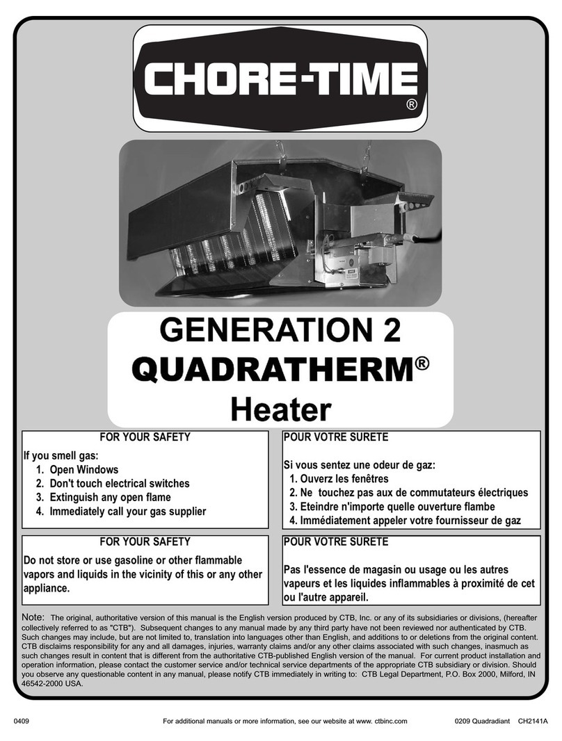
Chore-Time Generation 2 QUADRATHERM QUADRADIANT User manual

For additional manuals or more information, see our website at www.ctbinc.com 1
Note: The original, authoritative version of this manual is the English version produced by CTB, Inc. or any of its subsidiaries or divisions, hereafter
collectively referred to as "CTB"). Subsequent changes to any manual made by any third party have not been reviewed nor authenticated by CTB.
Such changes may include, but are not limited to, translation into languages other than English, and additions to or deletions from the original
content. CTB disclaims responsibility for any and all damages, injuries, warranty claims and/or any other claims of any nature associated with such
changes, inasmuch as such changes result in content that is different from the authoritative CTB-published English version of the manual. For current
product installation and operation information, please contact the customer service and/or technical service departments of the appropriate CTB
subsidiary or division. Should you observe any questionable content in any manual, please notify CTB immediately in writing directed to: CTB Legal
Department, P.O. Box 2000, Milford, IN 46542-2000 USA.
FOR YOUR SAFETY
If you smell gas:
1. Open Windows
2. Do not touch electrical switches
3. Extinguish any open flames
4. Immediately call your gas supplier
FOR YOUR SAFETY
Do not store or use gasoline or other flammable
vapors and liquids in the vicinity of this or any other appliance
Low Pressure 24 Volt Direct Spark Ignition
CT2373
QDR-2414
English
Original use and assembly guide

For additional manuals or more information, see our website at www.ctbinc.com 2
WARRANTY
CTB, Inc. warrants each new product manufactured by it to be free from defects in material or workmanship for
one (1) year from and after the date of initial installation by or for the original purchaser. If such a defect is found
by Manufacturer to exist within the one-year period, the Manufacturer will, at its option, (a) repair or replace such
product free of charge, F.O.B. the factory of manufacture, or (b) refund to the original purchaser the original
purchase price, in lieu of such repair or replacement. Labor costs associated with the replacement or repair of the
product are not covered by the Manufacturer.
Conditions and Limitations
1. The product must be installed by and operated in accordance with the instructions published by the
Manufacturer or Warranty will be void.
2. Warranty is void if all components of the system are not original equipment supplied by the
Manufacturer.
3. This product must be purchased from and installed by an authorized distributor or installer or a certified
representative thereof or the Warranty will be void.
4. Malfunctions or failure resulting from misuse, abuse, negligence, alteration, accident, or lack of proper
maintenance, or from lightning strikes, electrical power surges or interruption of electricity, shall not be
considered defects under the Warranty.
5. This Warranty applies only to systems for the care of poultry and livestock. Other applications in industry,
commerce, or residential applications are not covered by this Warranty and are strictly prohibited. Any such use
will void the Warranty.
Manufacturer shall not be liable for any Consequential or Special Damage which any purchaser may suffer or
claim to suffer as a result of any defect in the product. “Consequential” or “Special Damages” as used herein
include, but are not limited to, lost or damaged products or goods, costs of transportation, lost sales, lost orders,
lost income, increased overhead, labor and incidental costs and operational inefficiencies.
THIS WARRANTY CONSTITUTES THE MANUFACTURER’S ENTIRE AND SOLE WARRANTY AND
THIS MANUFACTURER EXPRESSLY DISCLAIMS ANY AND ALL OTHER WARRANTIES, INCLUDING,
BUT NOT LIMITED TO, EXPRESS AND IMPLIED WARRANTIES AS TO MERCHANTABILITY, FITNESS
FOR PARTICULAR PURPOSES SOLD AND DESCRIPTION OR QUALITY OF THE PRODUCT FURNISHED
HEREUNDER.
Distributors are not authorized to modify or extend the terms and conditions of this Warranty in any manner or to
offer or grant any other warranties for the products in addition to those terms expressly stated above. An officer of
the Manufacturer must authorize any exceptions to this Warranty in writing. Manufacturer reserves the right to
change models and specifications at any time without notice or obligation to improve previous models.
Effective 08/08
Chore-Time Equipment
A Division of CTB, Inc.
P.O. Box 2000 Milford, Indiana 46542-2000 USA
Ph.: 574-658-4101 Fax: 877-730-5525
Email: ctb@ctbinc.com
Internet: http//www.ctbinc.com

For additional manuals or more information, see our website at www.ctbinc.com 3
Do not use the heater to heat human living areas. The intended use of the heater is to provide
warmth for poultry and hog buildings
Use only the type of gas being supplied to the unit as marked on it (Propane or Natural Gas). Do not
operate with improper fuel.
Before each use, a visual inspection of the heater is essential to insure safety and satisfactory
heating. Replace or repair defective components before operating heater. Failure to do so will void
warranty and could result in injury and property damage.
WARNING: Improper installation, adjustments, alteration, service or maintenance could cause
property damage, injury or death. Read the installation, operating and maintenance instructions thoroughly
before installing or servicing this equipment.
WARNING: Failure to follow WARNINGS in this manual could result in serious injury or significant
property damage.
Before lighting, sniff all around the appliance area for a gas odor. Be sure to sniff next to the floor
because propane gas is heavier than air and may temporarily exist at floor level.
DO NOT ALLOW POWER CORDS AND/OR GAS SUPPLY HOSES TO REST ON THER CANOPY, HANGING
BRACKETS OR OTHER HOT SURFACES OF THE UNIT OR TO COME WITHIN 12” OF THE HEATER.
DSI UNITS MUST BE PROPERLY GROUNDED. DO NOT ALTER ELECTRICAL CORD.
Plug in the three-prong power cord to a correctly grounded three-prong electrical outlet.
The installation of this appliance must in all cases conform with local and national building codes or
in the absence of local codes to the current National Fuel Gas Code ANSI Z223.1/NFPA 54, or the Natural Gas
and Propane Installation Codes, CSA B149.1 and B149.2.
Heaters must be electrically grounded in accordance with the National Electrical Code, ANSI/NFPA
70 or the current Canadian Electrical ode, CSA C22.1. Polarity of Line voltage and neutral wires must be
maintained. The total load of all heaters in a circuit must be considered for overload control of that circuit.
Power supply must have earth ground.
WARNING!
SERIOUS PERSONAL INJURY AND/OR DEATH MAY RESULT FROM USE OF THIS
HEATER IN AN UNVENTILATED BUILDING OR IN HUMAN LIVING AREAS.
THESE INSTRUCTIONS SHOULD BE LEFT WITH THE APPLIANCE AND THE USER TO
RETAIN FOR FUTURE REFERENCE.
READ THESE INSTRUCTIONS THOROUGHLY BEFORE INSTALLING, USING OR SERVICING
THIS EQUIPMENT.

For additional manuals or more information, see our website at www.ctbinc.com 4
QuadRadiant®
WARNING:
CAUTION
LOW PRESSURE 80,000 BTU Heater
Direct Spark Ignition
LP Gas 10” WC at outlet of control (10¼” Max.)
Natural Gas 5½” WC at outlet of control (5¾” Max.)
During normal operation, the surfaces of the unit become very hot. It is VERY
IMPORTANT that the power cords and gas supply hoses DO NOT TOUCH OR REST
ON ANY surface of the unit or to come within 12” of the heater.
The area directly above the unit becomes hot during normal operation of the
heater. DO NOT install electrical wiring, water lines or conduit above the heater.
DO NOT run gas supply hoses above the heater.
DO NOT ALLOW ANYONE WHO HAS NOT READ THESE INSTRUCTIONS TO
INSTALL, ASSEMBLE, LIGHT, ADJUST OR OPERATE THIS HEATER.
THIS HEATER IS TO BE INSTALLED BY CERTIFIED INSTALLERS ONLY.
ONLY PERSONS WHO CAN UNDERSTAND AND FOLLOW THESE
INSTRUCTIONS SHOULD USE OR SERVICE THIS HEATER.
HEATER IS SHIPPED PRE-ASSEMBLED
TOOLS REQUIRED FOR INSTALLING HEATER:
¾” wrench for tightening gas connections
11/16” wrench
2 pipe wrenches
¼” nut driver
! WARNING!
Failure to read and
understand operator’s
manual and all safety signs
could result in serious injury.
Manual must remain with
equipment.

For additional manuals or more information, see our website at www.ctbinc.com 5
THE STATE OF CALIFORNIA REQUIRES THE FOLLOWING WARNING:
WARNING;
Combustion by-products produced when using this product contain carbon monoxide, a chemical known
to the State of California to cause cancer and birth defects (or other reproductive harm).
CAUTION:
This appliance is hot during normal operation. Avoid physical contact.
DANGER:
Do not attempt to clean the heater while it is operating or while it is still hot.
WARNING
GAS PRESSURE EXCEEDING 10¼” WC FOR LP OR 5¾” WC
FOR NATURAL GAS MAY VOID WARRANTY.
USE THREADED GAS CONNECTIONS ONLY.
HEATER MUST BE CONNECTED TO GAS SUPPLY USING THE
DRIP LEG, HOSE AND CONNECTORS PROVIDED WITH THE
UNIT BY THE MANUFACTURER.
ALLOW HEATING UNIT TO COOL
BEFORE WINCHING, CLEANING
OR SERVICING.
DO NOT ALLOW GAS HOSES OR
POWER CORDS TO TOUCH HOT
SURFACE.
DO NOT TOUCH HOT
EMITTER PANELS.
BEFORE USING HEATER CHECK
ALL FITTINGS AND
CONNECTIONS FOR LEAKS.
DO NOT USE OPEN FLAME TO
CHECK FOR LEAKS.
USE SOAP AND WATER TO
CHECK FOR LEAKS.
TO AVOID INJURY, ALWAYS
DISCONNECT ALL POWER
SUPPLY TO THE UNIT BEFORE
CLEANING OR SERVICING.
ROUTINE MAINTENANCE IS
REQURIED FOR OPTIMAL
HEATER PERFORMANCE AND
SAFETY.

For additional manuals or more information, see our website at www.ctbinc.com 6
QuadRadiant®Heater Installation Checklist
Installation topics
Checkmark below
when complete
1. Gas Pressure at Heater
Q. Have you verified that your gas pressure at the heater is 10¼” WC-LP Gas Maximum or
5¾” WC Natural gas Maximum t outlet of control?
A. See page 16 in the installation and operation manual.
2. Gas Hoses and Power Cords
Q. Are your gas hoses and power cords positioned properly away from heater?
A. See page 9, 10, 15 in the installation and operation manual.
3. Purging the Gas Lines
Q. Before attaching the hose, have you purged all gas lines?
A. See page 7, 16 in the installation and operation manual.
4. Drip Leg
Q. Have you installed a drip leg or sediment trap for each heater?
A. See page 7 in the installation and operation manual.
5. Floor and Ceiling Clearance
Q. Are your heaters the correct distance from the floor and ceiling?
A. See page 11 in the installation and operation manual.
6. Heat Shields
Q. Have you installed all the heat shields on all of the heaters?
A. See page 11 in the installation and operation manual.
7. Sensor Location
Q. Have you positioned your temperature sensor correctly?
A. See page 17 in the installation and operation manual.
8. Hanging
Q. Are your heaters’ hanging points positioned properly, and are all heaters hanging level?
A. See page 10, 11, 14 in the installation and operation manual.
9. Air Movement
Q. Have you ensured that there will be no direct air blowing on the heaters?
A. See page 9, 10 in the installation and operation manual.
10. Cleaning
Q. Have you established a cleaning schedule for the heaters and orifices?
A. See page 18 in the installation and operation manual.
This checklist provides only a limited set up and operational information. Reference the complete installation & operating manual for the
QuadRadiant ® heater to familiarize yourself with all operational risks and requirements in their entirety. Failure to follow complete installation &
operation instructions contained in the product manual(s) shall be considered misuse of the product and could result in personal injury and/or
property damage.

For additional manuals or more information, see our website at www.ctbinc.com 7
Install drip leg on gas line
The manufacturer requires the installation of the drip leg in order to help keep the gas orifice free from
debris commonly found in gas lines. Use approved and certified sealant on all connections.
WARNING!
Failure to follow the instructions in this manual can result in serious personal injury or
property damage.
Horizontal Inlet
Vertical Inlet
GAS FLOW
GAS FLOW
GAS FLOW
GAS FLOW
Attach to main gas supply here.
Attach the certified and approved BLACK high
pressure gas hose (supplied with unit) here to
supply fuel to unit.
For Component list,
see page 23.
CAUTION: Purge gas supply line of any contaminants before attaching the swivel end of certified and
approved BLACK high pressure gas hose assembly (supplied with unit) to valve. Tighten using ¾” and 11/16”
wrenches.

For additional manuals or more information, see our website at www.ctbinc.com 8
Control Installation
5. Remove boot from igniter.
4. Secure with two screws.
8. Slide boot onto igniter wire.
6. Slide boot onto igniter wire.
3. Slide control onto burner.
1. Remove tape & bag of screws.
2. Align burner and control.
7. Connect wire to igniter.

For additional manuals or more information, see our website at www.ctbinc.com 9
AIR MOVEMENT
Position heaters so there is no direct air movement on the heater.
Stir fans, inlets and tunnel doors should not blow directly on the units (During minimum ventilation, lock off
inlets that affect heater operation).
Check all heaters to be sure flame is not blowing outside the emitter.
Do not run heaters during tunnel ventilation.
Control end of heater should be towards tunnel fan end.
The gas supply inlet must be installed so that the gas supply hose is away from the surface of the heater.
Electrical supply must be installed so that electrical power cord is away from the surface of the unit.
The gas supply hose and the electrical power cord must not touch or rest on any surface of the heater
during operation of the unit or rest on the unit while the heater is being winched up or down.
The gas supply installation shown in the illustration above allows the gas supply hose to hang AWAY from
the surfaces of the heater even during winching of the unit.
This is the CORRECT method for installing the gas supply hose.
THIS HOSE INSTALATION IS CORRECT
AIR FLOW

For additional manuals or more information, see our website at www.ctbinc.com 10
SUSPENDING THE HEATER
NOTE: We recommend that the heater be installed level. Keep gas hose away from hot surfaces.
The heater is attached to a winch cable used for raising and lowering.
In addition, a safety cable or chain (not supplied) is required to be attached to the suspension hooks to
prevent the heater from falling to the litter if the cable should happen to break.
HEATER SAFETY CLEARENCE
The heater must be located so there is a minimum clearance to combustible material of 24’ (minimum of 12’
if the heat deflectors are used) above the heater and 48” from the side.
The heater should be hung with a minimum of 72” from the bottom of the heater and the floor.
We require a minimum clearance of 12” from the heater to the fuel and electricity supply lines.
The installer MUST comply with all applicable local, state, and federal gas codes and regulations.
:
Control end should be on end toward Tunnel Fans
12”
Gas and Electrical Supply Lines
Always allow heater to cool off before winching unit up to ceiling!
Materials that come in close proximity to hot surfaces may ignite.
Tunnel Fan End

For additional manuals or more information, see our website at www.ctbinc.com 11
WITH DEFLECTORS
12”
72”
MISSING DEFLECTORS
This is only a temporary adjustment. Heaters REQUIRE the installation of HEAT DEFLECTORS.
24”
72”
WARNING!
Do not allow power cords and/or gas supply hoses to rest on the canopy, hanging brackets or
other hot surfaces of the unit or within 12” of the heater. Failure to follow these instructions
could result in serious personal injury of significant property damage.
WARNING!
Failure to follow the instructions in this manual could result in serious personal injury or property
damage.
WARNING!
Failure to comply with all applicable local, state, and federal gas codes could result in serious
personal injury and/or serious property damage.

For additional manuals or more information, see our website at www.ctbinc.com 12
Each Unit requires two Left Deflectors and two Right Deflectors.
NOTE: Narrow, holed side of the deflectors face
toward the outer side of the heater.
NOTE: Full side of deflectors face to the center of
the heater.

For additional manuals or more information, see our website at www.ctbinc.com 13
Align tabs of deflectors with slots on heater and insert tab into slots completely so that deflectors are
flush against unit.
Using pliers, bend the tabs to secure deflectors to the heater.
Bend these tabs toward the outer edge.
Bend these tabs towards the inside.

For additional manuals or more information, see our website at www.ctbinc.com 14
NOTE: Do not mount this heater directly below electrical wiring that is exposed or in conduit.
NOTE: During and after winching, make certain that ALL hoses and power supply cords are NOT resting
on the heater nor are within 12” of the heater.
Pulley should be mounted in the ceiling and positioned 6” wider than the
suspension points n the heater.
Cable
Suspension
Chain and Carabiner
Suspension
Cable Suspension
Chain and Carabiner Suspension

For additional manuals or more information, see our website at www.ctbinc.com 15
THIS HOSE INSTALATION IS
WRONG!
The gas supply hose is
touching the heater.
More of the hose will rest on
the heater during winching.
THIS HOSE INSTALATION IS
WRONG!
The gas supply hose is
touching the heater.
More of the hose will rest on
the heater during winching.
THIS HOSE INSTALATION
IS WRONG!
The gas supply hose will
rest on the heater during
winching

For additional manuals or more information, see our website at www.ctbinc.com 16
CHECK ALL GAS PIPING AND CONNECTIONS FOR LEAKS BEFORE OPPERATING HEATER
It is recommended that the regulator be sized to 30% of the load being supplied.
Gas layout and pipe sizing guidelines are available through your distributor.
GAS PRESSURE should be CHECKED AND ADJUSTED to recommended settings.
Pressure exceeding 10¼” WC (LP) or 5¾”WC (Nat) could void warranty.
CAUTION: Purge gas supply line of any contaminants before attaching the swivel end of certified and
approved BLACK high pressure gas hose assembly (supplied with unit) to valve. Tighten using ¾” and 11/16”
wrenches.
To check gas pressure:
FIRST –Go to the furthest heater from the regulator and connect the pressure gauge to the Pressure Tap on the
side of the control. (See below) Turn “ON” only the heater you are testing or if you have a zone system, turn
“ON” all the heaters in the zone. Set the pressure at a Maximum of 10¼” WC (LP gas) or 5¾” WC (NAT gas).
SECOND –Turn “ON” all stoves in the house on the same regulator and check the pressure again. The pressure
should not drop below 9½” WC (LP gas) or 5¼” WC (NAT gas). If the pressure falls below that shown, the
distribution system is inadequately designed. The problem may be a regulator (size or quantity), pipe sizing or
other restrictions in the system.
WARNING
Failure to comply with all applicable local, state, and federal gas codes could result in serious personal
injury and/or serious property damage.
Pressure tap
CHECK GAS PRESSURE HERE
GAS SUPPLY INLET
Part#11000058
Adapter ⅜”MPT X ⅜”MF
Install hose through bushing
at end of control bracket.

For additional manuals or more information, see our website at www.ctbinc.com 17
WIRING INSTRUCTIONS FOR 24 VOLT ZONE HEATERS
1. Mount Power Supply in convenient location near electrical panel WITHIN 3 FEET OF OUTLET. Outlet should
be separately fused –15 AMP.
2. Mount junction box over each thermostat location selected.
3. Run 14-2 romex from connections on Power Supply to nearest junction box and continue on the other
junction boxes (if used).
4. Run 14-2 romex over each line of brooders to be hooked up to Zone Control. Lines should be run adjacent
the gas line. If more than one thermostat (zones) is to be used –black wire should be cut between zones.
5. Cut outer insulation ONLY on romex over each brooder to expose black and white wires. DO NOT OR STRIP
WIRES. Bare ground wires in not used.
6. Using “T” tap connectors connect wire from brooder valve (24V) to romex—white to white; black to black.
Note—cut off excess wire from valve.
7. Connect together in junction box using wire nuts:
a. Black from Power Supply, Black to next junction box (if used), Black from thermostat.
b. White from Power Supply, White to next junction box (if used), White from line over brooders.
c. White from thermostat to black from line over brooders.
8. Light brooders in usual manner and set ZONE thermostat for desired temperature.
9. Check for voltage drops to brooder.
(See Wiring Diagram on Pg. 23)
Thermostat Location
Locate thermostat at feed line between center of heater and 10ft from center, 12 to 16
inches from the floor
10’
10’
10’-12’

For additional manuals or more information, see our website at www.ctbinc.com 18
MAINTENANCE
Proper care and maintenance of your heater cannot be over emphasized!!
A POORLY MAINTAINED HEATER WILL:
-Raise Operating Cost –due to poor combustion - Lower Air Quality
-Cause Inconsistent Temperatures - Decrease the Life of the Heater
BEFORE PERFORMING ANY MAINTENANCE ON THE HEATER,
MAKE CERTAIN THAT ALL POWER AND FUEL HAS BEEN SHUT OFF TO THE UNIT.
-Daily: Check burner, flames should be burning clear and blue; if not, clean as required or
check gas pressure.
-Clean heater after each flock.
Clean orifice with soft brush and blow out with compressed air. Do Not clean the orifice with a wire or drill
because it will increase orifice hole and result in over firing the emitter.
-BURNER: Run the Bottle Brush in and out of the burner air intake openings located next to the orifice at the
outlet of the control valve. Clean off burner ports with Bottle brush.
-EMITTERS: Clean the back and front of the emitters using the Small Wire Brush and the Bottle Brush from the
underside and inside the unit.
-CANOPY AND REFLECTORS: Compressed air can be used to clean dust and dirt from canopy, reflector pan,
emitters and burner ports. Blow out the inside of the burner assembly using compressed air. Bottle Brush and
small Wire brush can also be used to clean the top of canopy, reflector pan and the catch pan under the burner.
-BLOW OUT AND OFF the burner and complete unit with a leaf blower or compressed air after loosening the
dust.
-FOR WASH DOWN APPROVED MODELS ONLY!
-POWER WASH DOWN INSTRUCTIONS;
-MAXIMUM WATER PRESSURE: 2,600 PSI @ 2.3 gpm nozzle: Fan Type –minimum 25 degree.
-DISTANCE FROM NOZZLE TO PARTS: 12 to 18 inches.
-TURN OFF GAS SUPPLY AND DISCONNECT ELECTRICAL POWER. WAIT FOR HEATER TO COOL BEFORE CLEANING.
Follow Safety Instructions to power wash equipment.
1. Wash down complete heater while keeping the nozzle moving and NO CLOSER THAN 12” from any part of the
heater.
2. After washing heater, raise the end opposite the control to empty the burner of water from wash down. Allow 1
hour for heater to dry before lighting.
-Check ignitor and burner ports for debris; wipe clean with steel wool and clear burner ports with wire.
-If heater is disconnected from the gas line, use tape to seal the open connections. This will keep moisture, dust,
and insects out and prevent future problems.
-INSPECT THE HOSE AND POWER CORD for any damage and safe clearance to heater, if damage is detected,
replace damaged parts before operating the heater.DO NOT ALLOW A HOSE AND/ OR A POWER CORD TO
TOUCH OR REST ON ANY SURFACE OF THE HEATER OR TO COME WITHIN 12”OF ANY PART OF THE HEATER.
-TURN GAS SUPPLY AND ELECTRICAL POWER BACK ON. LIGHT AND CHECK THE HEATER FOR PROPER
OPERATION.
WARNING!Never spray penetrating oil (WD-40) on the control valve. This will cause the loss of high
temperature valve grease and cause valve to leak.
Failure to follow these instructions could result in serious personal injury or significant property damage.

For additional manuals or more information, see our website at www.ctbinc.com 19
24V DUST-TIGHT XTD CONTROL
ASSEMBLIES
16550447 ASY, XTD CTL DT 24V DSI LP
16550448 ASY, XTD CTL DT 24V DSI LP HA
16550449 ASY, XTD CTL DT 24V DSI NAT
16550450 ASY, XTD CTL DT 24V DSI NAT HA
16550451 ASY, XTD CTL DT 24 V DSI B/P
16550452 ASY, XTD CTL DT 24V DSI B/P HA
16550086
SPACER, BURNER/INNER CONE-SHORT
2 each
16550038
HEAT DEFLECTOR LEFT
2 each
16550037
HEAT DEFLECTOR RIGHT
2 each
16550015 CANOPY
1 each
16550081 CENTER SUPPORT CANOPY
1 each
16550080 END PLATE CONTROL END
1 each
16550079 END PLATE OPPOSITE CONTROL
END 1 each
165050126 IGNITION CONTROL BOX TOP
1 each
16050127 CONTROL BOX BOTTOM
1 each

For additional manuals or more information, see our website at www.ctbinc.com 20
16550085
PAN/CHANNEL REFLECTOR
2 each
16550089
CORRUGATED INNER CONE
1 each
16550082
BOTTOM FLAME SHIELD
1 each
16550084
EMITTER PANEL
12 each
16050048
INSULATION, END PANEL
2 each
16050046 INSULATION, BOTTOM PANE 1 each
16050047 INSULATION, SIDE PANEL 2 each
16550093 BURNER ASSEMBLY 1 each
Other manuals for Generation 2 QUADRATHERM QUADRADIANT
1
Table of contents
Other Chore-Time Heater manuals
Popular Heater manuals by other brands
Rowenta
Rowenta CO3030 user guide
Proton
Proton Guard G710 Operation manual
Baxi
Baxi Luna Duo-tec Series Supplementary manual for the installer
solamagic
solamagic IR 05001 Installation and instruction manual
Dimplex
Dimplex PLX 2000TI Installation and operating instructions

Speidel
Speidel 47059 operating instructions
