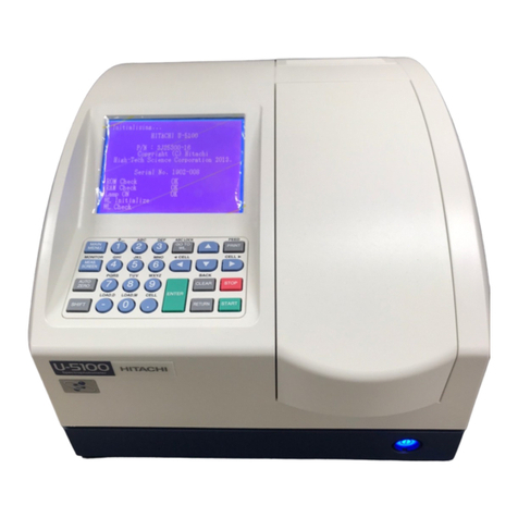
Chore-Time Chore-Tronics User manual

Chore-Tronics®
Load Cell Indicator
MT2316AJune 2008

CTB Inc. Warranty Load Cell Indicator
2MT2316A
CTB Inc. warrants each new product manufactured by it to be free from defects in material or workmanship
for one year from and after the date of initial installation by or for the original purchaser. If such a defect is
found by the Manufacturer to exist within the one-year period, the Manufacturer will, at its option, (a) repair
or replace such product free of charge, F.O.B. the factory of manufacture, or (b) refund to the original
purchaser the original purchase price, in lieu of such repair or replacement. Labor costs associated with the
replacement or repair of the product are not covered by the Manufacturer.
Conditions and Limitations
1. The product must be installed by and operated in accordance with the instructions published by the
Manufacturer or Warranty will be void.
2. Warranty is void if all components of the system are not original equipment supplied by the Manufacturer.
3. This product must be purchased from and installed by an authorized distributor or certified representative
thereof or the Warranty will be void.
4. Malfunctions or failure resulting from misuse, abuse, negligence, alteration, accident, or lack of proper
maintenance shall not be considered defects under the Warranty.
5. This Warranty applies only to systems for the care of poultry and livestock. Other applications in industry
or commerce are not covered by this Warranty.
The Manufacturer shall not be liable for any Consequential or Special Damage which any purchaser may
suffer or claim to suffer as a result of any defect in the product. “Consequential” or “Special Damages” as
used herein include, but are not limited to, lost or damaged products or goods, costs of transportation, lost
sales, lost orders, lost income, increased overhead, labor and incidental costs and operational inefficiencies.
THIS WARRANTY CONSTITUTES THE MANUFACTURER’S ENTIRE AND SOLE WARRANTY
AND THIS MANUFACTURER EXPRESSLY DISCLAIMS ANY AND ALL OTHER WARRANTIES,
INCLUDING, BUT NOT LIMITED TO, EXPRESS AND IMPLIED WARRANTIES AS TO
MERCHANTABILITY, FITNESS FOR PARTICULAR PURPOSES SOLD AND DESCRIPTION OR
QUALITY OF THE PRODUCT FURNISHED HEREUNDER.
CTB Inc. product Distributors are not authorized to modify or extend the terms and conditions of this
Warranty in any manner or to offer or grant any other warranties for CTB Inc. products in addition to those
terms expressly stated above. An officer of CTB, Inc. must authorize any exceptions to this Warranty in
writing. The Manufacturer reserves the right to change models and specifications at any time without notice
or obligation to improve previous models.
Effective: July 2008
CTB Inc.
P.O. Box 2000 • Milford, Indiana 46542-2000 • U.S.A.
Phone (574) 658-4101 • Fax (877) 730-8825
Thank You
The employees of CTB Inc. would like to thank your for your recent purchase. If a problem should arise, your
CTB distributor can supply the necessary information to help you.
CTB Inc. Warranty

Load Cell Indicator Overview
MT2316A 3
The Chore-Tronics Load Cell Indicator is used to indicate the amount of weight in a maximum of two
different feed bins that are setting on two different sets of loadcells.
facility.
Description of Control Front Panel
Viewing Screen
The viewing screen has a display which has 4 lines, each containing 20 characters. This is the area that will
display the requested information when a subject button is pressed. The viewing screen always remains lit.
Normally the Current Weight screen shows (Figure 2).
Overview
Introduction to the Control
Item Description
1 Navigation Buttons
2 Viewing Screen
3 Edit Buttons
4 Subject Buttons
Figure 1. Introduction to Control
4
1
2
3
Figure 2. Current Weight Screen.
Silo Bin 1 123456
Silo Bin 2 123456
CHECK ALARMS
06 Sep 2007 10:03a

Introduction to the Control Load Cell Indicator
4MT2316A
Navigation Buttons
These buttons allow you to scroll up and down in the screens that have more than 8 lines. Continuously
pressing the up or down arrow button increases the scrolling speed. When you are in the Edit Mode the left
and right arrow keys move the cursor to editable (changeable) positions. The cursor highlights the areas that
can be changed.
Edit Buttons
When the button labeled EDIT is pressed and you are looking at a screen that has editable fields, the cursor
appears. With the Navigation Buttons, you can move the cursor to the parameter on the screen that you want
to edit. By pressing the “+” or “–” buttons, the numerical values are changed. If you are changing text (i.e.
“yes” or “no”), the "+" and "–" keys scroll through the possible text choices. Pressing the EDIT button a
second time exits the edit mode.
Fast Edit
While editing a number on the screen, you will notice that the digit you are changing is underlined. For
example: (72.0). If you wish you can move to different digits of the number in order to change the number
more rapidly. To do this See Figure 3 below. Fast Edit is very useful when making large changes to numbers.
Security
To provide for security in setting your Controls, there is a security feature that appears when you press the
Edit button. The Control automatically asks for an access code at that time, The access code is a four digit
number that you have selected while setting up the Control and is explained under the “Changing the Access
Code”section of this manual. Once you have inserted the correct code, the Control allows you to make
changes. If five minutes pass since your last change, the access code has to be re-entered.
Subject Buttons
On the front of the Control are 3 subject keys. As each subject button is pressed, the light beside that button
turns on and the subject that is described beside the button appears on the screen. If no other buttons are
pressed for 5 minutes, the Control automatically returns to the Current Weight screen.
72.0
Press "+" followed by "-"
Within 3 seconds, Press the Left arrow twice 72.0
Press "+" twice arrow 92.0
Mt1701-065 1/02
72.0
Press the Edit button
Action Result
Figure 3. Fast Edit.

Load Cell Indicator Introduction to the Control
MT2316A 5
How to Maneuver in the Viewing Screen
•The procedures below give a brief overview on the use of the Navigation Buttons and the Edit Buttons.
•Screen 1, "Setup" is used for this example.
Using the Navigation Buttons
1. Press BUTTON 1. Figure 4 appears in the display.
2. Press the DOWN ARROW once.
The view shown on the screen will scroll down one line as shown in Figure 5. If you push the UP ARROW
once, the text scrolls back to where it was.
3. The left and right arrow keys are used during the Edit Mode.
Figure 4. Navigation Buttons.
Silo Bin 1 123456
Silo Bin 2 123456
CHECK ALARMS
06 Sep 2007 10:03a
Figure 5. Press Down Arrow.
Silo Bin 2 123456
CHECK ALARMS
06 Sep 2007 10:03a

Introduction to the Control Load Cell Indicator
6MT2316A
Using the Edit Buttons
The Edit Mode is entered by pressing the Edit Button. Pressing the Edit Button a second time exits the Edit
Mode.
1. Press BUTTON 3.
The Setup screen appears (Figure 6).
2. Press the EDIT button.
This activates the cursor which allows settings to be edited. Figure 7 shows what the cursor looks like. If
the Control asks you for an "Access Code", enter it at this time (See Page 44).
3. Press the (+) or (–) buttons to edit the House #.
The (+) key increases the value and the (–) key decreases the value.
4. Press the DOWN ARROW (Figure 8).
5. Press the (+) or (–) buttons to change from Fahrenheit to Celsius.
In this case the (+) and (–) buttons select different text choices.
6. If two or more editable settings are on the same line, the left and right arrow buttons are used to move
between those positions.
When a value or text is edited, it is saved in the memory within a few seconds. If you make a mistake, rechange
it to what you really want.
Figure 6. Setup Screen.
Control Number 1
Clock Type 12 HR
Time 11:01p
Figure 7. Setup Screen in Edit Mode.
CURSOR
Control Number 1
Clock Type 12 HR
Time 11:01p
Figure 8. Setup Screen in Edit Mode.
Control Number 1
Clock Type 12 HR
Time 11:01p

Load Cell Indicator Glossary of Terms
MT2316A 7
Noticing an Alarm
“Noticing” an alarm is a very important part of using the alarm system. With button presses, you can tell the
Control that you have “seen” the alarm message. The simplest way to do this is to first press the alarm button
to read the alarm message(s) at the top of the alarm screen. Each additional press of the alarm button (while
you’re still looking at the alarm screen) “notices” the alarm(s), one at a time.
SJB Box (Scale Junction Box)
The SJB Box translates information from the Loadcells to the LCI. Each SJB can be connected to a maximum
of 6 Loadcells. A maximum of two SJB’s can be connected to the LCI.
Screen 1: Current Weight
Screen 1 (Figure 9) shows a brief summary of the current conditions of the house. There are no editable values
in this screen; it is for viewing only.
1. Silo Bin 1- The current weight in Bin #1.
2. Silo Bin 2- The current weight in Bin #2.
3. Check Alarms- This will appear (flashing) if the LCI detects an alarm condition. This will continue
to appear until the condition is corrected and noticed.
4. Date and Time- Current date and time.
Screen 2: Alarms
At the top of Screen 2, all current alarm conditions will be
listed. If there are no alarm conditions, the status of the alarm
will show at the top of the screen. The three possible statuses
are ENABLED, DISABLED, and TEST. The status field is
editable. See the "Alarms" section of this manual for more
alarm information.
1. For this example, a power failure has occurred and
recovered; this information is at the top of the screen
and will remain there until the alarm is NOTICED.
2. The time, date and type of alarm of the most recent
10 alarms are listed in the lower part of the screen.
Glossary of Terms
Overview of Screens
Figure 9. Weight Screen
Silo Bin 1 123456
Silo Bin 2 123456
CHECK ALARMS
06 Sep 2007 10:03a
1
23
4
Pwr Fail Recovered
Alarm sys Enabled
Hi Temp 10.4 ( 87.5)
LoTemp -11.6 (54.6)
---------------------
Alarm History:
10 most recent alarms list-
ed here.
Figure 10. Auxiliary Data Screen
1
2

Screen 3: Setup Load Cell Indicator
8MT2316A
Screen 3: Setup
1. Control number- Set the LCI's control number here.
2.Clock Type- Choose the desired clock type to use (12 hour or 24 hour)
3.Time and Date- Set the current time and date.
4.Total Silo Bins- The total number of silo bins connected to the control.
5.Calibrate Silo Bin 1(2)- This where the loadcells are calibrated. After connecting the LCI, SJB and
Loadcells, make sure there is no feed in the bin. Answer YES to the Zero line to zero calibrate the
loadcells. The Acutal = line should now read 0. Next place a known weight on the bin. Enter this
weight on the weight line. When the proper weight has been entered answer YES on the Weight line
to calibrate the span of the loadcells. Remove the known weight and the number in the Actual
Weight line should return to 0.
NOTE: The units of measurement are chosen at calibration. If the number entered in the weight line is in
pounds, than the LCI will weigh in pounds. If the number entered in the weight line is in Kilograms, then the
scale will weigh in Kilograms.
6.Access Code- There is always an access code. From the factory the value is set at "1111". The 1111 is
a special code that tells the control not to ask for an access code when the edit button is pressed. If it is
desired, the access code can be changed to a 4 digit number. To change the access code answer YES to
change access code at the bottom of screen 3. Then enter the desired 4 numbers buy pressing the sub-
ject buttons on the front of the control. If an access code can not be recalled please contact your Chore-
Time distributor or service representative.
Figure 11. Setup Screen
Control Number 1
Clock Type 12 HR
Time 11:01p
Date 25 Aug 06
Total Silo Bins 1/2
CALIBRATE SILO BIN 1
Actual = 123456
Zero Y/N
Weight = 123456 Y/N
CALIBRATE SILO BIN 2
Actual = 123456
Zero Y/N
Weight = 123456 Y/N
Ch. Access code? Y/N
2
3
4
1
5
6

Load Cell Indicator Initial Setup Procedure
MT2316A 9
Once the LCI has been properly installed, the LCI is ready to be setup.
1. Go to the Setup Screen (Screen 3) by pushing button 3.
2. Setup the LCI Control number, time, and date. Key in the LCI how many bins are connected totthe LCI.
3. Follow the calibration prodedure to calibrate the Loadcells of each Bin.
When all of the data has been entered into the Setup Screen (Screen 3), the LCI is now ready to display the
weight in the Bin.
Initial Setup Procedure

Control Operation Overview Load Cell Indicator
10 MT2316A
In Screen 1 (Button 1) the weight of each Bin is displayed. The unit of measure displayed depends upon how
the LCI was calibrated in the Setup Screen.
Alarms
At the top of screen 2 a current alarm condition(s) will be listed. If there are no alarm conditions, the status of
the alarm system will show at the top of the screen. The three possible statuses are ENABLED, DISABLED,
and TEST. The status field can be changed.
Enabled
If the alarm system is ENABLED and one or more alarms arise, there will be alarm message(s) at the top of
the screen. After pressing the screen 2 button the first time, the alarm Relay will be changed to the non alarm
state for one minute and the alarm-screen will be shown. By pressing the screen 2 button a second time the
alarm message will change from ALARM to the status NOTICED. This second button press is the manner
that you tell the Control that you are aware of the alarm condition and, in so doing, NOTICE the alarm
condition. If there is more than one alarm condition, you NOTICE each additional alarm condition with an
additional button press for each additional alarm condition. If you fail to NOTICE an alarm with the additional
button press(s), the alarm Relay will return to the alarm state one minute after the initial screen 2 button press.
If the alarm condition is still present when you NOTICE the alarm, the word ALARM to the right of the
condition will (for most alarm conditions) change to OFF FOR 24:00. The time setting is editable. It gives you
time to deal with the problem. If you do not fix the problem, the alarm Relay will once again trigger your alarm
system at the end of the time period. If the alarm condition has RECOVERED by the time you NOTICE the
condition, the alarm message disappears when you NOTICE it and it is added to the alarm history at the
bottom of the alarm screen.
Disabled
It is possible, but not recommended, to DISABLE the alarm system of the Control. One reason for this could
be that the house is empty. The light beside the screen 2 button will flash slowly to remind you that the alarm
system is disabled, but the alarm Relay will not change to the alarm state. The alarm history shown at the
bottom of screen 2 does list that the alarm system was disabled, when, and for how long.
Test
If the user chooses TEST, the alarm Relay will immediately change to the alarm state. This allows testing the
alarm system that is external to the Control (telephone dialer, for instance.) NOTICING the ALARM TEST,
as you would a normal alarm, erases the alarm message and returns the alarm Relay to the non alarm state.
Also, an ALARM TEST notification will be listed in the alarm history.
Warning
There also is an alarm message status called WARNING. This does not change the state of the alarm Relay,
but alerts you that something isn’t right. It needs to be NOTICED in the same way as a “hard” alarm in order
to turn off the flashing lights, etc. An example is a failed Sensor.
Alarm History
At the bottom of the alarm screen is a listing of the most recent 10 alarms. The date and time of each alarm is
shown. The amount of time elapsed (hh:mm) from the time the alarm occurs until the alarm is noticed and
recovers is also show.
Control Operation Overview

Load Cell Indicator Control Installation
MT2316A 11
Alarm Messages
SJB 1 (or 2) IO Net Error
This alarm will occur when the LCI can not communicate with one of the SJB boxes. Check to make sure that
the SJB boxes are connected properly to LCI, that the address DIP switches are set properly and that there is
power to the SJB. See the wiring diagram on page 14 for information on connecting the SJB to the LCI.
Service Alarms
Listed below are additional alarm codes that relate to the internal operation of the LCI. Contact the nearest
Chore-Time Distributor or CTB service personnel if one of these alarms occur.
Mounting the Control
The LCI Control requires a minimum mounting area of
approximately 10" x 14" [55.9 cm x 55.9 cm] This
dimension is allowing extra room for the Control Door
to open. (See Figure 12). The box should be mounted
level on a solid backing using the mounting holes
provided.
SYSTEM FAILURE 100
SYSTEM FAILURE 111
ERROR 1
ERROR 2
ERROR 3
ERROR 4
ERROR 5
ERROR 6
ERROR 7
ERROR 8
ERROR 20
ERROR 21
ERROR 22
ERROR 23
ERROR 27
ERROR 29
ERROR 30
ERROR 33
ERROR 34
ERROR 35
ERR 103
Control Installation
Approx. 10"
Extra room for Door to open
Approx. 14"
Figure 12. Control Mounting

Wiring Diagram Load Cell Indicator
12 MT2316A
Wiring Diagram
120 OHM RESISTOR
REQUIRED AT THE
BEGINING AND END
OF THE I/O NET
TWISTED PAIR I/O NET
+
-F NET
TO PC HOOK UP
(MUST HAVE C CENTRAL)
230 VAC 50/60 HZ
SUPPLY
+ TO I/O NET
- TO I/O NET
TWISTED PAIR
+24 VOLT SUPPLY TO
SJB (MAX 6 CELLS)
-24 VOLT
SUPPLY TO
SJB (MAX 6
CELLS)
+ TO I/O NET
- TO I/O NET
SUPPLY VOLTAGE
100 - 240 VAC
50/60 HZ. 0.6
AMP.
120 OHM RESISTOR
-+
SJB Control
2ND
SJB Control
I/O NET
I/O NET
+
-
I/O NET
120 OHM RESISTOR
-+
24V EXT GND
NCNO
C
RELAY
ALARM
- I/O +
FNET NET
230 VAC 50/60 HZ.
INCOMING POWER
L1 L2
LCI CONTROL

Load Cell Indicator Part Numbers
MT2316A 13
Part Numbers
Item Description Part No.
1 Plate, Model 4B Top 41327
2 4 x 20 Display 41318
3* Plain Control Box Lid 30859-1
4 Control Box 30860-3
5* Control Box Lid 30859-1
6 KD Board 41316
7 Grounding Rail 43384-2
8 Plate, Mod 4B, SP, NV Bottom 41328
9 Control Box Latch 30862
10 Box Latch Pivot 30863
11 I/O.3 Board 41312
12 LCI Decal 2529-906
*Not Shown
2
7
7
11
12
1
9
10
4
6
8

Part Numbers Load Cell Indicator
14 MT2316A
Note: The original, authoritative version of this manual is the [English] version produced by
CTB, Inc. or any of its subsidiaries or divisions, (hereafter collectively referred to as "CTB").
Subsequent changes to any manual made by any third party have not been reviewed nor
authenticated by CTB. Such changes may include, but are not limited to, translation into
languages other than [English], and additions to or deletions from the original content. CTB
disclaims responsibility for any and all damages, injuries, warranty claims and/or any other
claims associated with such changes, inasmuch as such changes result in content that is different
from the authoritative CTB-published [English] version of the manual. For current product
installation and operation information, please contact the customer service and/or technical
service departments of the appropriate CTB subsidiary or division. Should you observe any
questionable content in any manual, please notify CTB immediately in writing to: CTB Legal
Department, P.O. Box 2000, Milford, IN 46542-2000 USA.
Revisions to this Manual
Page No. Description of Change
New Manual
CTB Inc.
P.O. Box 2000 • Milford, Indiana 46542-2000 • U.S.A.
Phone (574) 658-4101 • Fax (877) 730-8825
Other manuals for Chore-Tronics
1
Table of contents

