Waltron 9033X User manual

101-044-E.1
EXPERTS IN WATER CHEMISTRY SINCE 1903
9033X Sodium Analyzer
User Manual

9033X
2
Waltron User Manual 101-044-E.1
9033X Sodium Analyzer
WALTRON CUSTOMER COMMITMENT
This user manual is a technical guide to aid the customer in the set-up and maintenance
of their new Waltron measuring system. Waltron provides continuous product
improvement and reserves the right to make any modifications to the information
contained herein without notice.
Copyright © Waltron Bull & Roberts, LLC, 2022
All Rights Reserved
Technical questions concerning this product should be addressed to:
Waltron Technical Service Department
25 Minneakoning Rd, Suite 101
Flemington, New Jersey 08822
Phone: +1 908 534 5100, option 3 Fax: +1 908 534 5546
www.waltron.net
Please be ready to provide the following information:
Date analyzer was purchased.
Analyzer model and serial number.
Recent maintenance history.
Calibration slope values and detailed description of problem.
Waltron’s technical expertise and extensive experience provides personalized solutions
to the water quality industry. It is Waltron’s commitment to provide the customer with
timely and accurate technical service and support.
Waltron fully expects the customer to be satisfied with the quality, performance, and
cost of this product. If there are any questions or concerns regarding this product,
please feel free to contact Waltron at.
Thank you for choosing Waltron!
Please note Waltron mailing and UPS shipping addresses:
DIRECT ALL CORRESPONDENCE AND SHIPMENTS TO:
Waltron Bull & Roberts, LLC
25 Minneakoning Rd, Suite 101
Flemington, NJ 08822

9033X
3
3
Waltron User Manual 101-044-E.1
9033X Sodium Analyzer
Safety:
Please observe proper safety and handling precautions when installing, operating,
maintaining, and servicing this product. The following should be noted and adhered to:
Read and understand manual before working with analyzer.
Pay special attention to warning labels on enclosures, containers, packages
and chemicals.
Only qualified personnel should be involved in the installation, operation,
and servicing of the analyzer.
Follow safety precautions when operating analyzer in conditions of high
pressure and/or temperature.
Keep analyzer chemicals away from heat and extreme temperatures.
Reagent powders must be kept dry.
Follow all regulations and warning labels when disposing of chemicals. Do
not mix chemicals.
To obtain analyzer safety information or Safety Data Sheets
(SDS), please contact Waltron or logon to www.waltron.net .

9033X
4
Waltron User Manual 101-044-E.1
9033X Sodium Analyzer
Warranty Agreement
If, within one year from the date of shipment, the customer experiences any equipment
defects or is not satisfied with the analyzer manufacturing, Waltron will repair, or at its
option, replace any defective part(s) free of charge. This warranty requires that the
defective part(s) be returned to Waltron with shipping charges prepaid.
At Waltron discretion, a Technical Service Specialist may be sent out to repair or replace
the defective part(s) on location. Traveling time and expenses of the Technical Service
Specialist is at the customer’s expense.
Equipment sent to Waltron must be appropriately packaged and the following
information must be provided prior to returning to Waltron:
The Return Authorization (RA) number assigned to the customer by the
Waltron Technical Service Department.
Customer name, address and department.
Name and telephone number of the individual responsible for returning
items for repair.
Brief problem description.
Ship to Waltron Service Center:
Waltron Bull & Roberts, LLC
25 Minneakoning Rd, Suite 101
Flemington, NJ 08822

9033X
5
5
Waltron User Manual 101-044-E.1
9033X Sodium Analyzer
Checklist of Materials
In order to ensure customer satisfaction, Waltron does its best to provide adequate and
timely packaging and shipping services. Please perform the following after receiving a
shipment:
Inspect all shipping containers upon receipt and record any visible damage. If
there are any outward signs of damage, please retain all containers and
packages for inspection by carrier. Please retain all packing material so that it
can be used for future moving and shipping needs.
Check all items received against those on the packing list. Chemicals are
usually shipped in a separate package and will be itemized accordingly.
Verify that the number of packages received agrees with the packing list and
shipping papers.
Notify both Waltron and the carrier if any problems occur.
Important Notice
All monitors are inspected and tested prior to shipment.
In normal use, the unit should require only minor maintenance and should
operate correctly and without fault over a long period of time.
Please note that if electronic components need to be replaced, it may be
necessary to adjust and/or calibrate the monitor.
Failure to carry out correct maintenance procedures may result in inaccurate
monitor reading.

9033X
6
Waltron User Manual 101-044-E.1
9033X Sodium Analyzer
Table of Contents
1INTRODUCTION...................................................................................................8
1.1 GENERAL ............................................................................................................. 8
1.2 MAIN FEATURES.................................................................................................. 8
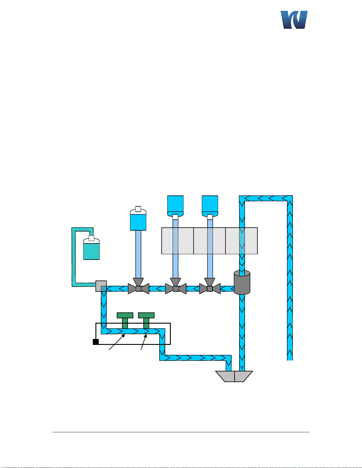
1.3 SYSTEM DESCRIPTION & ARCHITECTURE............................................................ 9
1.3.1 WET SECTION UNIT ...................................................................................... 10
1.3.2 PRE-AMPLIFIER............................................................................................. 11
1.3.3 TRANSMITTER UNIT ..................................................................................... 11
2INSTALLATION...................................................................................................11
2.1 MOUNTING OF ANALYZER ................................................................................ 11
2.1.1 LOCATION AND LAYOUT .............................................................................. 12
2.1.2 TRANSMITTER UNIT ..................................................................................... 12
2.2 SAMPLE REQUIREMENTS.................................................................................. 12
2.3 EXTERNAL PIPING CONNECTIONS..................................................................... 13
2.4 ELECTRODE INSTALLATION ............................................................................... 13
2.4.1 PROBE CONNECTIONS.................................................................................. 13
2.4.2 GEL FILLED REFERENCE ELECTRODE (ALTERNATE) ...................................... 14
2.4.3 AUTOMATIC KCL REFILL SYSTEM (OPTIONAL) ............................................. 15
2.4.4 PROBE INSTALLATION PROCEDURES ........................................................... 16
2.5 ELECTRICAL CONNECTIONS............................................................................... 17
2.5.1 WET SECTION UNIT ...................................................................................... 17
2.5.2 PRE-AMP UNIT ............................................................................................. 18
2.5.3 TRANSMITTER UNIT ..................................................................................... 19
3OPERATING THE ANALYZER ...............................................................................23
3.1 ANALYZER OPERATION ..................................................................................... 23
3.2 ALARMS............................................................................................................. 25
3.3 GETTING STARTED ............................................................................................ 25
3.4 SOFTWARE PROGRAMMING ............................................................................ 25
3.4.1 SOFTWARE STRUCTURE MAP ...................................................................... 26
3.4.2 MAIN MENU –USER MODE......................................................................... 26
3.4.3 COMMANDS WINDOW................................................................................ 27
3.4.4 DISPLAY WINDOW ....................................................................................... 32
3.4.5 MAIN MENU –SERVICE MODE .................................................................... 36
3.4.6 SERVICE MENU............................................................................................. 39
3.4.7 AUTO CALIBRATION ..................................................................................... 41
3.4.8 CALIBRATION FAILURE ................................................................................. 41
4TROUBLESHOOTING –CALIBRATION FAIL...........................................................42
5MAINTENANCE..................................................................................................43
5.1 BUFFER SOLUTION(S)........................................................................................ 43
5.2 STANDARD SOLUTIONS..................................................................................... 44
5.3 ETCHING SOLUTION.......................................................................................... 44
5.4 REFERENCE ELECTRODE FILL SOLUTION (For Use with N3010-174) ............... 45
5.5 SCHEDULED SERVICING..................................................................................... 45
5.5.1 WEEKLY ........................................................................................................ 45

9033X
7
7
Waltron User Manual 101-044-E.1
9033X Sodium Analyzer
5.5.2 MONTHLY..................................................................................................... 45
5.6 SHUT-DOWN PROCEDURE - (Prolonged Shut-Down, 1+ months).................... 46
5.6.1 STORAGE OF ELECTRODES ........................................................................... 47
5.7 pH EFFECTS........................................................................................................ 47
6SPARE PARTS.....................................................................................................48
7TROUBLE-SHOOTING .........................................................................................50
8SPECIFICATIONS ................................................................................................53
9APPENDIX..........................................................................................................54

9033X
8
Waltron User Manual 101-044-E.1
9033X Sodium Analyzer
1INTRODUCTION
1.1 GENERAL
The Waltron 9033X Sodium Analyzer is a microcontroller-based unit used for online
measurement of sodium content in various water chemistry/treatment applications.
Sampling points for power generation include mixed bed outlets, extraction pump
discharge, boiler feed, boiler drum and steam. The measurement range of the 9033X
analyzer spans from 0.01ppb to 10ppm.
1.2 MAIN FEATURES
Features of the 9033X Sodium Analyzer unit include:
1. Measurement of sodium concentration
oWide range analysis - 0.01ppb to 10ppm. Concentration and
temperature are displayed continuously and analyzer adjusts
automatically to user specified ranges.
oAutomatic temperature compensation
oProtection from “Hot Sample”
oGrab sample measurement
oMissing sample flow switch
2. Calibration
oSingle & two point calibration
oProcess calibration
oFully automatic calibration (single & two point)
oLow reagent and standard consumption
oInternal diagnostics used to show probe status
3. User Interface
o4.5” color touch screen HMI
oLarge easy to read graphic display
4. Communication Interface via RS-485 using MODBUS RTU protocol
5. Analyzer Configuration :
oUser configurable settings for recorder outputs and alarm set points
oFactory defaults can easily be reloaded to override user setting
6. Automatically stores last 10 calibration and alarm logs.
7. Complete analyzer diagnostics
8. 3 Relay outputs for High, Low and General Alarm
9. Two 4-20mA isolated current outputs
10. Quick connect electrodes with probe positioning clamps
11. Redesigned drain for easy sample pH measurement
12. Automatic KCl refill system (optional)

9033X
9
9
Waltron User Manual 101-044-E.1
9033X Sodium Analyzer
1.3 SYSTEM DESCRIPTION & ARCHITECTURE
The 9033X Sodium analyzer system is comprised of the following:
1. Wet-Section (Sensor Unit)
a. Reagent solution containers
b. Hydraulic panel consisting of constant head, flowcell, tubing, thermistor
and 3 solenoid valves
c. Sodium and reference electrodes
d. 2 sodium standard solution containers (CAL1 and CAL2)
e. Grab sample bottle
2. Pre-Amp unit
3. Transmitter (electronics) unit
Figure 1. Overall system architecture.
Reagent
Solution
Hydraulic
Panel
Standard
CAL2
Grab
Sample
Pre-amp
(Behind
Panel)
Standard
CAL1
Transmitter

9033X
10
Waltron User Manual 101-044-E.1
9033X Sodium Analyzer
1.3.1 WET SECTION UNIT
The 9033X Sodium system is capable of monitoring sodium concentrations in sample
feed. Three solenoid valves are used to select between analyzing the sample,
calibration solution 1 (CAL1), calibration solution 2 (CAL2) and grab sample.
In normal mode, the feed water flows through the flow switch, into the heat exchanger,
through the solenoid valves and into the flowcell where it comes into contact with the
sodium and reference electrodes. The electrodes transmit a voltage proportional to the
sodium content in the feed water. This output is then measured by the electrical system
and converted into a ppb/ppm measurement. An internal thermistor (housed in
flowcell) is used to monitor the sample temperature for temperature compensation. If
the sample temperature exceeds 131°F, sample automatically gets diverted to drain and
the system displays “HOT”.
Figure 2. Sample flow during normal operation.
Sample
Inlet
Heat
Exchanger
Solenoid
1
Constant
Head Unit
Solenoid
2
Solenoid
3
Flowcell
Reference
Electrode
Measuring
Electrode
Thermistor
Entrainment
“T”
Reagent
Bottle
High
Calibration
Bladder
Grab
Sample
Bottle
Low
Calibration
Bladder
Overflow
Drain
Waste
Drain

9033X
11
11
Waltron User Manual 101-044-E.1
9033X Sodium Analyzer
1.3.2 PRE-AMPLIFIER
The 9033X Sodium analyzer requires a pre-amplifier unit which amplifies and converts
the voltage output from the electrodes into proportionate current. Thermistor output is
also fed to transmitter unit via pre-amp section. The pre-amplifier houses the wiring
connection terminals from electrodes. The DIN style cables from the pre-amplifier allow
for quick and easy change-out of electrodes.
1.3.3 TRANSMITTER UNIT
The transmitter unit interprets electrode response and temperature output from the
pre-amp and displays the corresponding sodium concentration (in ppb/ppm) and
temperature. The transmitter unit controls all the operations of the analyzer system.
The display is a touch screen HMI.
2INSTALLATION
2.1 MOUNTING OF ANALYZER
Figure 3. Dimensions to mount the Wet Section. (All dimensions in inches)
Ø 0.94”
Ø 0.48”
0.63”
0.69”
10.25”
10.25”
32.0”
33.5”
14.50”
Ø 0.48”
0.88”

9033X
12
Waltron User Manual 101-044-E.1
9033X Sodium Analyzer
2.1.1 LOCATION AND LAYOUT
Mount the analyzer in a clean, vibration-free area avoiding direct radiant heat, sunlight
and drafts. Avoid areas containing chlorinating equipment. The 9033X Sodium analyzer
default design has the two main sections (transmitter and wet section) combined as a
single unit. If necessary the sensor unit can be mounted separately as long as it is no
more than 330 feet (100meters) from the transmitter unit.
2.1.2 TRANSMITTER UNIT
The transmitter unit controls the operations of the analyzer. Power supply, CPU card,
Analog card and input power terminal junction are housed in the transmitter enclosure.
Transmitter unit is a NEMA 4X rated enclosure with cable glands for wiring. Size and
layout of transmitter is shown below.
Figure 4. Dimensions of the transmitter unit. (All dimensions in inches)
2.2 SAMPLE REQUIREMENTS
The maximum sample pressures and temperatures specified in the SPECIFICATION
section should not be exceeded. The sample should be introduced to the system at a
temperature and pressure suitable for measurement. If necessary, customer may
choose to use sample cooling and pressure reducing equipment. It is highly
recommended that a flow meter is installed to the sample inlet stream to ensure that
the sample flow rate is within the specified range. When pressure reducing equipment
is being used, a pressure relief valve should be installed between the sample point and
sample inlet to ensure maximum safety.

9033X
13
13
Waltron User Manual 101-044-E.1
9033X Sodium Analyzer
2.3 EXTERNAL PIPING CONNECTIONS
Figure 5. The bottom of the wet section case, with the sample inlet and drain
connections shown.
2.4 ELECTRODE INSTALLATION
2.4.1 PROBE CONNECTIONS
Figure 6. Placement of electrodes in the flowcell.
Buffered Sample
Drain
Outlet 3/8” ID
Sample Inlet
¼” ID
Swagelok
Sodium
(Measuring)
Electrode
Reference
Electrode (Refillable
version shown)
Flowcell
Quick connect
electrode connection
Probe positioning
clamp (finger tighten)
Wires coming
from Pre-Amp
Sample Overflow
Drain
Outlet 3/8” ID

9033X
14
Waltron User Manual 101-044-E.1
9033X Sodium Analyzer
2.4.2 GEL FILLED REFERENCE ELECTRODE (ALTERNATE)
The Gel filled reference electrode has an inner element consisting of a gel solution
which does NOT require electrolyte refilling.
Sodium
(Measuring)
Electrode
Reference
Electrode
Flowcell
Quick connect
electrode
connection
Probe
positioning
clamp (finger
tighten)
Wires coming
from Pre-Amp
Adjust tip 5-10mm
into sample

9033X
15
15
Waltron User Manual 101-044-E.1
9033X Sodium Analyzer
2.4.3 AUTOMATIC KCL REFILL SYSTEM (OPTIONAL)
Figure 7. Layout of the Automatic KCl Refill System.
Directions for installing and using the KCl refill system:
1. Feed inner (smaller diameter) tubing through outer (larger diameter) tubing.
2. Feed inner tubing through the side-arm of the reference electrode and connect
the outer tubing over the side-arm.
3. Clip nozzle of KCl bottle, making sure the hole is large enough for inner tubing to
pass through and that KCl solution can flow freely around it.
4. Insert inner tubing through nozzle of bottle and connect outer tubing over the
nozzle of bottle. Make sure the inner tubing reaches the top of the bottle while
the other end remains inside the reference electrode.
5. Install KCl bottle into the bottle clamp and finger-tighten wing nut to hold the
bottle in place.
6. Poke a small hole in the top of the bottle so KCl flows freely and vacuum does
not form.
7. Rinse off any spilled KCl with DI water before installing probe in the flowcell.
(KCl will interfere with sample reading if it gets in the flowcell.)
KCL Solution
Reservoir Bottle
KCL Transfer
Tubing (outer)
Refillable
Reference
Electrode with
Side-arm
Connection for
Tubing
Bottle Clamp
End of internal air
tubing
Internal air tubing
(inner)

9033X
16
Waltron User Manual 101-044-E.1
9033X Sodium Analyzer
2.4.4 PROBE INSTALLATION PROCEDURES
1. Remove the protectors from the tip of each electrode
2. Connect electrodes to wires from Pre Amplifier. Be sure to match the correct
wires to the correct probe. Wires are marked “M” for measuring and “R” for
Reference.
3. Use fingers to rotate the probe positioning clamp counterclockwise to loosen.
Carefully insert the electrode through the clamp and into the flowcell.
Electrodes may have to be inserted at an angle.
4. For reference electrode - insert the electrode so that the tip of the electrode is
5mm into the sample. Correct placement within the flow cell is important. Refer
to figure below.
5. For measuring electrode –insert the electrode so that the tip is just off the
bottom of the flowcell. Refer to figure below.
Figure 8. Proper installation of the
electrodes in the flowcell.
Tip of measuring
electrode
positioned just off
bottom of flowcell
Tip of reference
electrode
positioned 5mm
into sample

9033X
17
17
Waltron User Manual 101-044-E.1
9033X Sodium Analyzer
2.5 ELECTRICAL CONNECTIONS
2.5.1 WET SECTION UNIT
Figure 9. The wet section layout and connections.
Constant Head
Solenoid 1 –CAL 1
Solenoid 2 –CAL 2
Solenoid 3 –G.S.
Heat Exchanger
(behind plate)
Sample Inlet
Sample Drain
Reference Probe
Measuring Probe
Thermistor
Entrainment T
KCl Refill Reservoir
Bottle Clamp
Grab Sample Bottle
Reagent Bottle
CAL 1 Bladder
CAL 2 Bladder
Overflow Drain

9033X
18
Waltron User Manual 101-044-E.1
9033X Sodium Analyzer
2.5.2 PRE-AMP UNIT
Figure 10. Pre-amplifier located behind the wet panel.
The pre-amplifier unit has 3 connection terminals (J1, J2, J3) shown below:
Figure 11. Pre-amplifier layout. Pin 1 of all the connectors is shown in black.
The following cables/connections are used in pre-amp system:
1. Multicore cable (8-Core) for interfacing the transmitter unit with pre-amp at J3.
Pin 1 (Black Wire)
Pin 2 (White/Black Wire).
Pin 3(Red Wire)
Pin 4(White Wire)
Pin 5(Red/Black Wire)
Pin 6(Green Wire)
Pin 7(Blue Wire)
Pin 8(Orange Wire)
Pin 4(Shield).
J1
J2
J3
Wiring from
Electrodes
Wiring from
Thermistor –J2
Pre-Amp Output to
Transmitter –J3

9033X
19
19
Waltron User Manual 101-044-E.1
9033X Sodium Analyzer
2. Multicore cable (2-Core PVC Shielded Twisted) for interfacing the thermistor with
pre-amp at J2.
Blue Wire : From +ve Thermistor to Pin 1 of J2
Red Wire : From -ve Thermistor to Pin 2 of J2
Black Heat Shrink (Shield) : From shield to Pin 3 of J2
2.5.3 TRANSMITTER UNIT
Proceed as follows to gain access when making the necessary connections:
Remove the six screws securing the top cover of the transmitter unit. Pass appropriate
cables thru the cable glands for the following connections:
Power Supply
Solenoid and Alarms
Pre-amp Input (sensor and thermistor wiring)
4-20mA Current Output and Communication Interface
Sample Flow Switch IF INSTALLED - OPTIONAL
Figure 12. The layout and connections for the transmitter case.
4-20 mA
Output
Flow Switch
(Optional)
Solenoid
Valves 1,2,3
Pre-Amplifier
HMI
RS485
Alarm
Relays
Power
Supply
Power
Input

9033X
20
Waltron User Manual 101-044-E.1
9033X Sodium Analyzer
Connecting the power supply earth (ground) ensures the safety of
assembly personnel, reduction of the effects of Radio Frequency
Interference (RFI), and ensures operation of the power supply
interference filter.
Before connecting the analyzer to the main power supply check that
there is correct voltage at the mains.
Although this instrument has internal fuse protection, the operator must
use a suitably rated external protection device such as a fuse or
miniature circuit breaker (MCB).
Switch OFF the power supply and high voltage power-operated control
circuits before making any connections. This equipment operates on
alternating current (AC) electricity. Always take suitable safety
precautions to avoid the possibility of an electric shock.
Table of contents
Other Waltron Measuring Instrument manuals

Waltron
Waltron 9091C User manual

Waltron
Waltron 3048 User manual

Waltron
Waltron Aqualert 6051 User manual

Waltron
Waltron 3049 User manual

Waltron
Waltron 9031CX User manual

Waltron
Waltron 2410 User manual

Waltron
Waltron 9092 User manual

Waltron
Waltron 9072 User manual

Waltron
Waltron 9032X User manual

Waltron
Waltron 9096 User manual