Page 4
Specifications are subject to change, since development is a continuous process,
So for more updated operating information and Support,
Please contact our Helpline: 9978991476/9978991482/9978991474 or
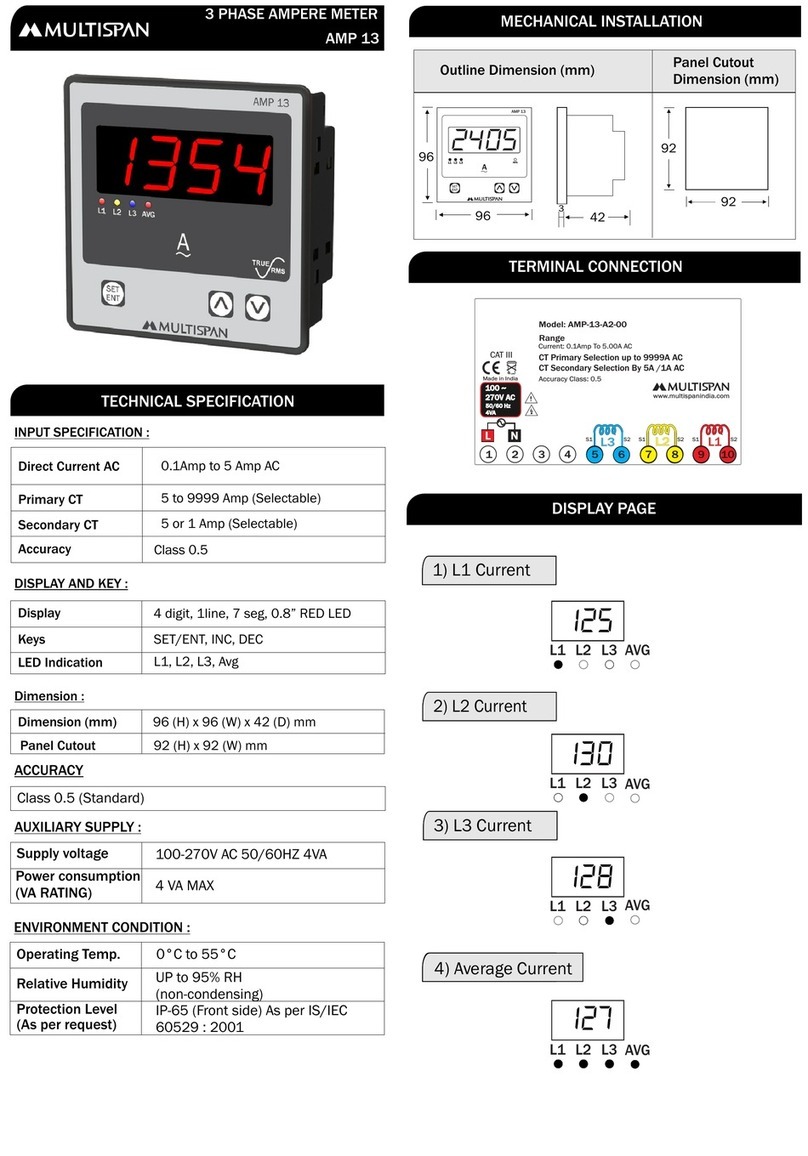
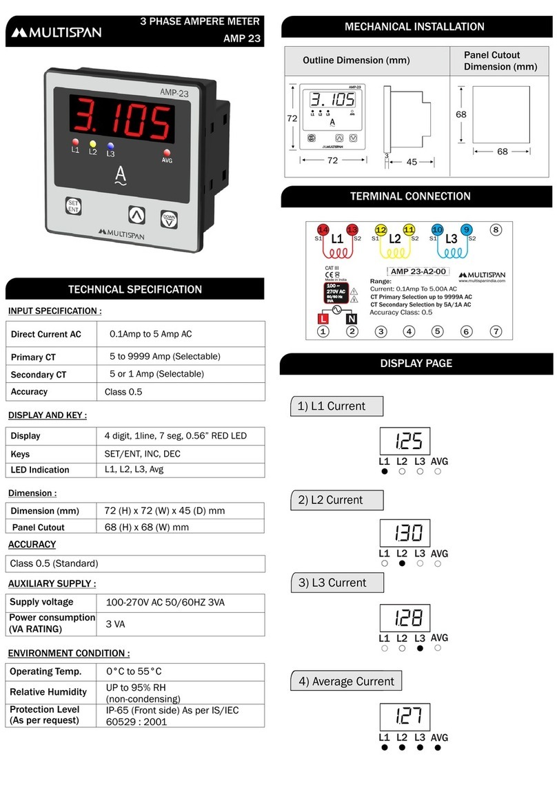
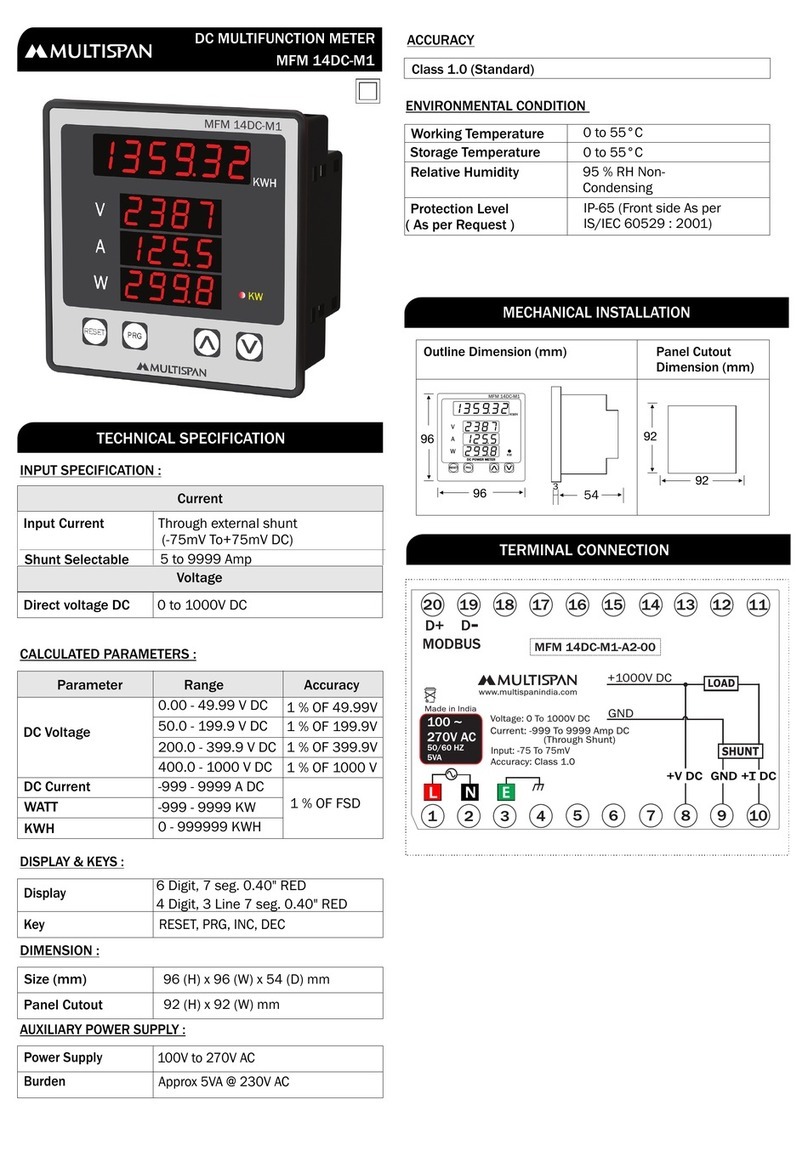
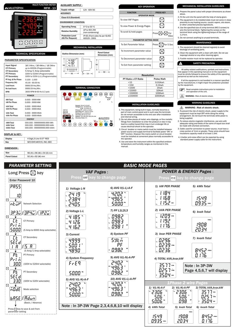
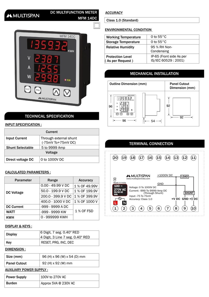
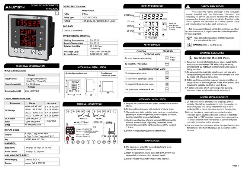
1. Prepare the panel cutout with proper dimensions as show
above.
2. Fit the unit into the panel with the help of clamp given.
3. The equipment in its installed state must not come in close
proximity to any heating source, caustic vapors, oils steam,
or other unwanted process by products.
4. Use the specified size of crimp terminal (M3.5 screws) to
wire the terminal block. Tightening the screws on the
terminal block using the tightening torque of the range of
1.2 N.m.
5. Do not connect anything to unused terminals.
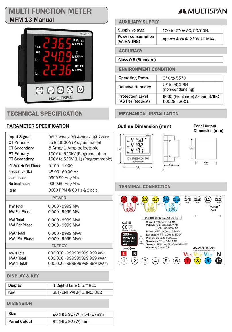
96 52
92
92
3
96
Outline Dimension (mm) Panel Cutout
Dimension (mm)
MECHANICAL INSTALLATION GUIDELINES
SAFETY PRECAUTION
!
All safety related codifications, symbols and instructions
that appear in this operating manual or on the equipment must
be strictly followed to ensure the safety of the operating
personnel as well as the instrument.
WARNING GUIDELINES
WARNING : Risk of electric shock.
1. To prevent the risk of electric shock power supply to the
equipment must be kept OFF while doing the wiring
arrangement. Do not touch the terminals while power is
being supplied.
2. To reduce electro magnetic interference, use wire with adequate
rating and twists of the same of equal size shall be made with
shortest connection.
3. Cable used for connection to power source, must have a cross
section of 1mm or greater. These wires should have insulations
capacity made of at least 1.5kV.
4. A better anti-noise effect can be expected by using standard
power supply cable for the instrument.
475
356
460
AVF133
Scroll
430
428
475
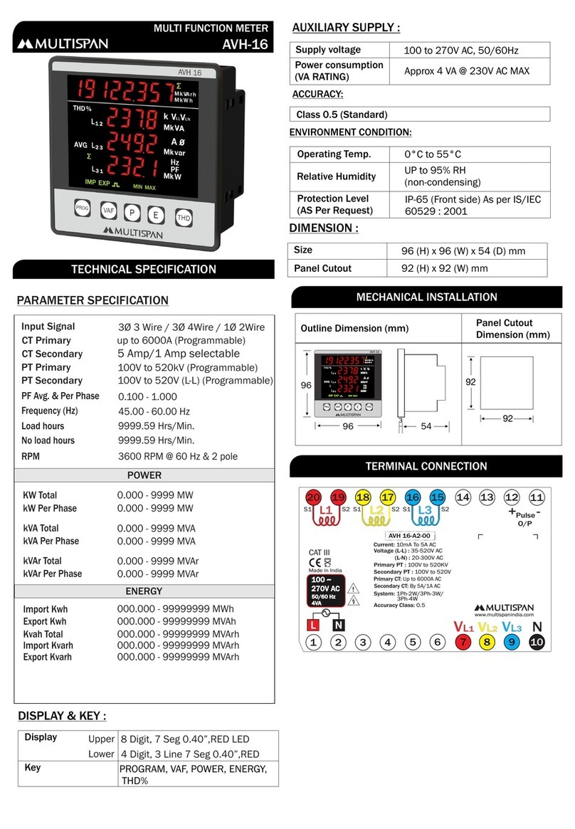
WIRING DIAGRAM
R
Y
S1
S1
S2
S2
3 Phase - 4Wire
R
Y
S1
S1
S2
S2
3 Phase - 3Wire
S1 S2
1 Phase - 2Wire
Read complete instructions prior to installation
and operation of the unit.
WARNING : Risk of electric shock.
If all the equipment is not handled in a manner specified
by the manufacturer, it might impair the protection provided
by the equipment.
B
N
S1 S2 B
Y
R
B
S1 S2 B
Y
R
N
L
MAINTENANCE
1. The equipment should be cleaned regularly to avoid blockage
of ventilating parts.
2. Clean the equipment with a clean soft cloth. Do not use
isopropyl alcohol or any other cleaning agent.
3. Fusible resistor must not be replaced by operator.
S1S2
L1
1234789
12
13
14
10
11
56
LN
3Ø-4W / 3Ø-3W /
System:
Current: 0.5 To 5A AC
1Ø-2W
CT Selection:
18 15
VLVLVLN
S1
S1
S2
S2
(L-L): 50-500V AC
(L-N): 30-300V AC
Voltage:
5/5 to 10KA/5
Accuracy Class: 0.5
100
270V AC
~
50/60 HZ
4VA !
Made in India
www.multispanindia.com
1920 17 16
CAT III
1 2 3
L2
L3
