Chore-Time 56310 Setup guide

Introduction
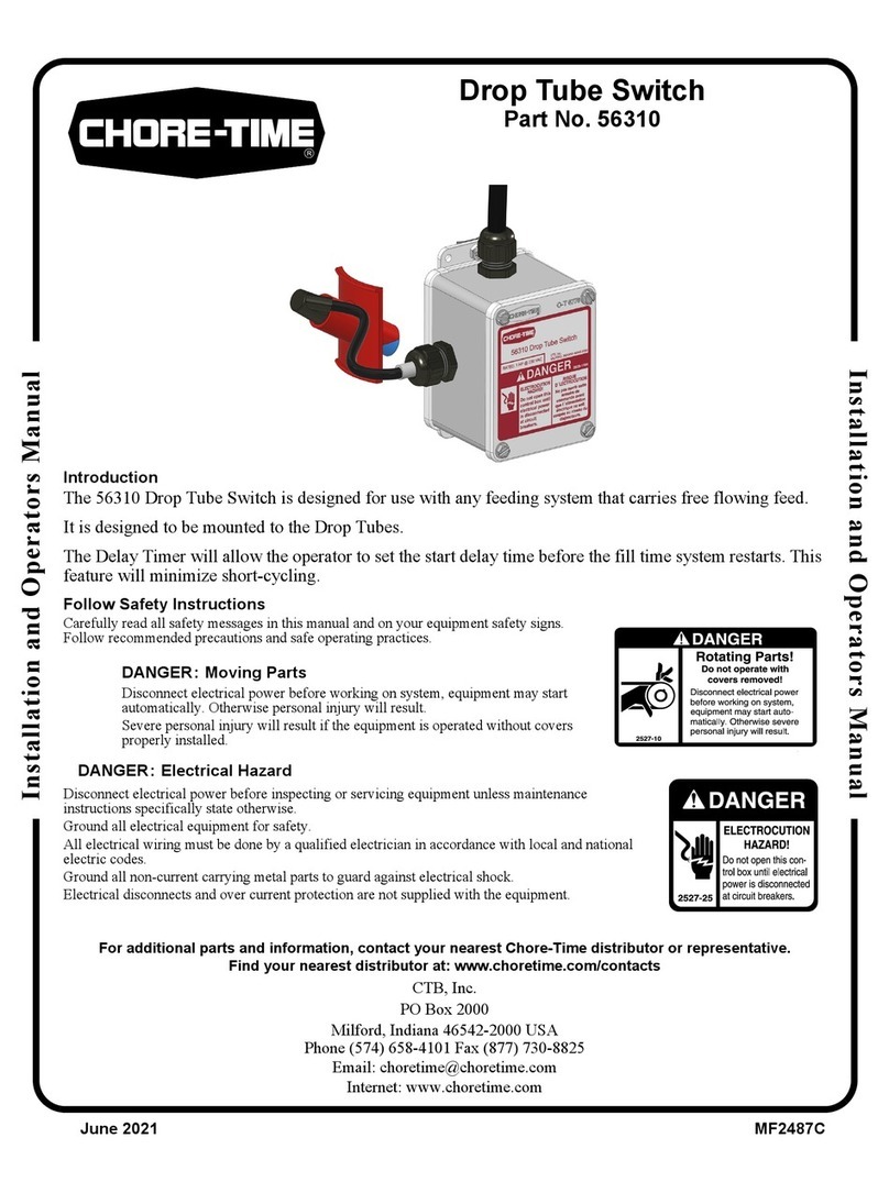
The 56310 Drop Tube Switch is designed for use with any feeding system that carries free flowing feed.
It is designed to be mounted to the Drop Tubes.
The Delay Timer will allow the operator to set the maximum run time for the auger to ensure that it will not
continue to operate if the feed bin runs out of feed.
Follow Safety Instructions
Carefully read all safety messages in this manual and on your equipment safety signs.
Follow recommended precautions and safe operating practices.
DANGER: Moving Parts
Disconnect electrical power before working on system, equipment may start
automatically. Otherwise personal injury will result.
Severe personal injury will result if the equipment is operated without covers
properly installed.
DANGER: Electrical Hazard
Disconnect electrical power before inspecting or servicing equipment unless maintenance
instructions specifically state otherwise.
Ground all electrical equipment for safety.
All electrical wiring must be done by a qualified electrician in accordance with local and national
electric codes.
Ground all non-current carrying metal parts to guard against electrical shock.
Electrical disconnects and over current protection are not supplied with the equipment.
Contact your nearby Chore-Time distributor or representative for additional parts and information.
Chore-Time Group, A division of CTB, Inc.
PO Box 2000
Milford, Indiana 46542-2000 USA
Phone (574) 658-4101 Fax (877) 730-8825
Email: [email protected]
Internet: www.choretime.com
MF2487ANovember 2019
Installation and Operators Manual
Installation and Operators Manual
Drop Tube Switch
Part No. 56310

Contents
Topic Page
MF2487A 2
Introduction. . . . . . . . . . . . . . . . . . . . . . . . . . . . . . . . . . . . . . . . . . . . . . . . . . . . . . . . . . . . . . . . . . . . . . . . . . 1
Follow Safety Instructions . . . . . . . . . . . . . . . . . . . . . . . . . . . . . . . . . . . . . . . . . . . . . . . . . . . . . . . . . . . . . . 1
DANGER: Moving Parts . . . . . . . . . . . . . . . . . . . . . . . . . . . . . . . . . . . . . . . . . . . . . . . . . . . . . . . . . . . 1
DANGER: Electrical Hazard . . . . . . . . . . . . . . . . . . . . . . . . . . . . . . . . . . . . . . . . . . . . . . . . . . . . . . . . 1
Installation. . . . . . . . . . . . . . . . . . . . . . . . . . . . . . . . . . . . . . . . . . . . . . . . . . . . . . . . . . . . . . . . . . . . . . 3
Switch assembly/Installation . . . . . . . . . . . . . . . . . . . . . . . . . . . . . . . . . . . . . . . . . . . . . . . . . . . . . . . . . . . . 3
Switch Adjustment . . . . . . . . . . . . . . . . . . . . . . . . . . . . . . . . . . . . . . . . . . . . . . . . . . . . . . . . . . . . . . . . . . . . 3
Wiring . . . . . . . . . . . . . . . . . . . . . . . . . . . . . . . . . . . . . . . . . . . . . . . . . . . . . . . . . . . . . . . . . . . . . . . . . 4
DANGER: Electrical Hazard . . . . . . . . . . . . . . . . . . . . . . . . . . . . . . . . . . . . . . . . . . . . . . . . . . . . . . . . 4
. . . . . . . . . . . . . . . . . . . . . . . . . . . . . . . . . . . . . . . . . . . . . . . . . . . . . . . . . . . . . . . . . . . . . . . . . . . . . . . . . . . 4
Parts Listing . . . . . . . . . . . . . . . . . . . . . . . . . . . . . . . . . . . . . . . . . . . . . . . . . . . . . . . . . . . . . . . . . . . . 5
56310 Drop Tube Switch . . . . . . . . . . . . . . . . . . . . . . . . . . . . . . . . . . . . . . . . . . . . . . . . . . . . . . . . . . . . . . . 5

Installation
3
MF2487A
Switch assembly/Installation
Mounting the Drop Tube Switch in the final Hopper Tubes lower than all other Hoppers will prevent all other
Hoppers from running out of feed before the Switch activates to fill the system.
Attach the Switch to the Drop Tube as shown.
Switch Adjustment
Drop Tube Switch is pre-adjusted at the factory to a
delay of "90" seconds. The delay may be changed for
a specific installation.
Time Delay Adjustment
•For Less Time: Turn the Time Delay
Adjustment Screw counter-clockwise (light
blinks faster).
•For More Time: Turn the Time Delay
Adjustment Screw clockwise. (light blinks
slower).
Installation
Figure 1.Installation
Item Description Part No.
1 Drop Tube Switch 56310
2 Drop Tube Switch Holder 56302
3 Proximity Sensor 56275
4 Hose Clamp 13948
Drill a 1" [2.54 cm] dia. Hole
in the Drop Tube at the desired
location for the Sensor.
3
2
4
1
1
Safety Timer
Adjustment Screw
Time Delay
Adjustment Screw
Figure 2.Switch Adjustment
Proximity Sensor

Wiring
4MF2487A
DANGER: Electrical Hazard
Disconnect electrical power before inspecting or servicing equipment unless maintenance instructions
specifically state otherwise.
Ground all electrical equipment for safety.
All electrical wiring must be done by a qualified electrician in accordance with local and national electric codes.
Ground all non-current carrying metal parts to guard against electrical shock.
Electrical disconnects and over current protection are not supplied with the equipment.
Wiring
Figure 3.Wiring

Parts Listing
5MF2487A
56310 Drop Tube Switch
Parts Listing
Item Description Part No.
1 Terminal Box Mounting Cover 6956
2 Relay Mount for Control 52316-2
3 Omron Relay 28904
4 General Purpose Box 42627-16
5 Switch Box Gasket 6777
6 Switch Box Cover 6776
7 Proximity Sensor 56275
8 Cord Assembly 4999-125
9 Mounting Bracket 52315
10 Pan H SFTP #6-32 Screw 35493
Item Description Part No.
11 #10 x .5 HXWH Screw 28075
12 5" Hose Clamp 13948
13 #6-32 x 3/8 Phil Pan H Screw 34660
14 .5 x 1.058 x .265 Nylon Lock Nut 43662
15 Lock Washer 305
16 Hx Lock Nut w/Nylon Insert 34019
17 Drop Tube Switch Holder 56302
18 Liquid Tight Connector 23779
19 .25 x 2 Vinyl Tubing 14454-2
20 56310 Drop Tube Switch Decal 2529-1194
16
2
3
4
5
5
6
7
9
8
11
13
12
10
13
14
17
18
19
20
11
1
15
18

MADE TO WORK.
BUILT TO LAST.®
Revisions to this Manual
Page No. Description of Change ECO
New Manual 34357
Contact your nearby Chore-Time distributor or representative for additional parts and information.
Chore-Time Group
A division of CTB, Inc.
PO Box 2000
Milford, Indiana 46542-2000 USA
Phone (574) 658-4101 Fax (877) 730-8825
E-mail:poultry@choretime.com
Internet: www.choretimepoultry.com
Table of contents
Other Chore-Time Switch manuals
Popular Switch manuals by other brands
Power integrations
Power integrations TinySwitch-III Series manual
CAMBRIONIX
CAMBRIONIX ThunderSync3-16 user manual
Dungs
Dungs GW A4 Series manual

Nimbra
Nimbra 300 Series Installation and maintenance manual

Nortel
Nortel Passport 7400 Hardware installation
Matrix Switch Corporation
Matrix Switch Corporation MSC-2HD1624L product manual
