manuals.online logo
Brands
  1. Home
  2. •
  3. Brands
  4. •
  5. Dungs
  6. •
  7. Switch
  8. •
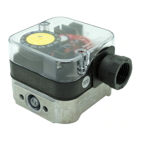
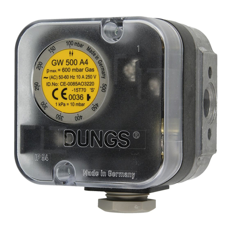
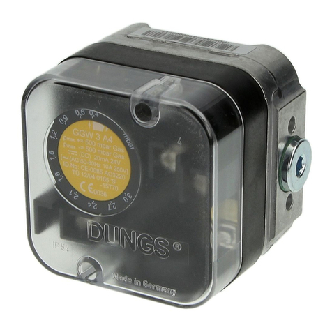
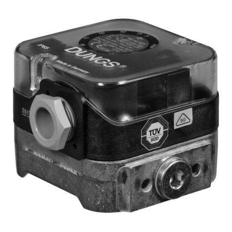
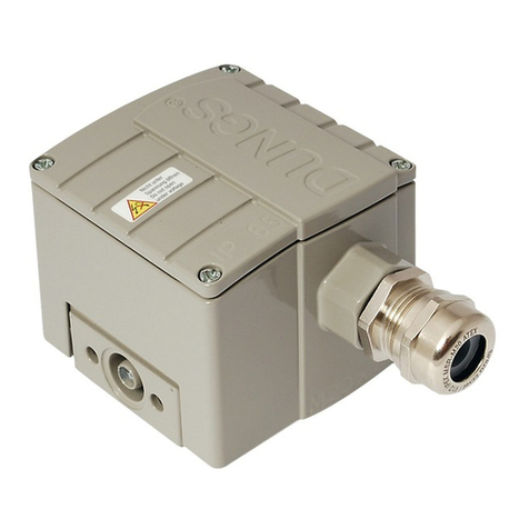
  9. Dungs GW A4 Series User manual

Dungs GW A4 Series User manual

1 … 6
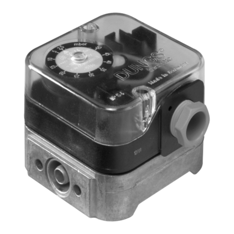
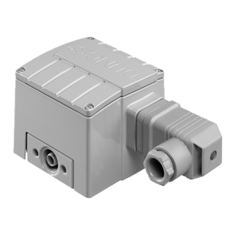
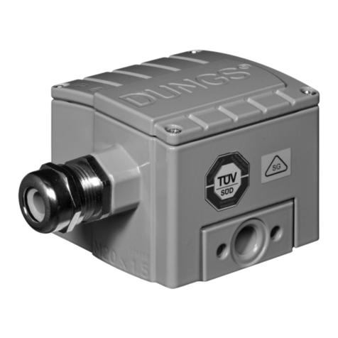
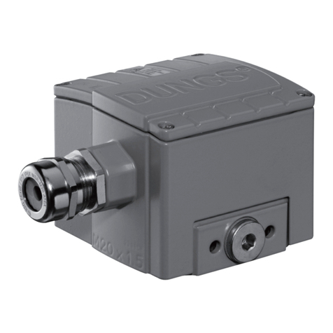
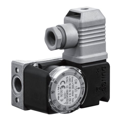
Compactpressureswitch
for gases and air
GW A4
Pressure limiters
ÜB A4 and NB A4
Double pressure switches
GW A4/ GW A4
5.02
Technical description
The GW A4 pressure switches, the
pressure limiters ÜB A4 and NB A4
and the double pressure switch GW
A4 / GW A4 are adjustable pressure
switchesforautomaticburnercontrols.
They are suitable for switching a cir-
cuit on, off or over on changes in
actual pressure value relative to the
set reference value.
Thereferencevalue(switchingpoint)is
adjusted on a setting wheel provided
with a scale. Test nipple integrated in
metal housing as standard.
Application
Pressure monitoring in firing, ventila-
tion and air-conditioning systems.
Suitableforgasesoffamilies1,2,3and
other neutral gaseous media.
Approvals
EU type test approval as per EU Gas
Appliance Directive. TÜV (German
TechnicalInspectorate)inspectionfor
pressureswitchesofspecialconstruc-
tionasperTRD604andVdTÜVTech-
nical Data Sheet, edition 100/1, as
well as Class "S" as per EN 1854.
GW...A4 CE-0085AO0012
ÜB...A4 CE-0085AO0026
NB...A4 CE-0085AO0039
Approvalsinotherimportantgas-con-
sumingcountries.Specialdesignsfor
the North American market with UL,
FM and CSA registrations.
Printed in Germany • Rösler Druck • Edition 08.00 • Nr. 214 747
2 … 6
Functional description
Single-actingpressureswitchorpres-
sure limiter in pressure range.
The pressure switches and/or pres-
sure limiters work without using any
auxiliary power.
GW A4 pressure switch
Thecontrolunitrespondstopressure.
If the set reference value is exceeded
or undershot, the circuit is switched
on, off or over.
ÜB A4, NB A4 pressure limiters
Thecontrolunitrespondstopressure.
Interlock is performed when the set
referencevalueisexceededorunder-
shot.
The "Locked" switching state is indi-
cated by a glow lamp.
Restart is only possible by activating
theresetbuttononthesettingwheelof
thepressurelimiteraftertheoperating
pressure is attained.
ÜB A4: Switches and locks when the
set pressure is exceeded.
NB A4: Switches and locks when the
set pressure is undershot.
Double pressure switch
GW A4 / GW A4
CombinationoftwoGWA4singlepres-
sure switches flanged together. The
setting of the two reference values is
performed separately and independ-
ently. This permits a combination of
differentreferencevaluesettingrang-
es. The same medium and pressure
are applied to the two control units.
GW A4 switching function
As pressure rises:
1 NC opens, 2 NO closes
As pressure falls:
1 NC closes, 2 NO opens
ÜB A4 switching function
As pressure rises
2 NO closes, 1 NC opens
Glow lamp ON, locked.
NB A4 switching function
As pressure falls
2 NO opens, 1 NC closes
Glow lamp ON, locked.
Operating state
Definition of switching difference ∆p
The switching difference ∆p is the
pressure difference between the up-
per and lower switching pressures
Pressure
at meter
Falling
Switching difference
∆p
Setting tolerance Upper switching
pressure
Lower switching
pressure
Adjustment as
pressure falls
Rising
COM NO
NC
2
1
p
3
N
COM NO
NC
2
1
p
3
COM NO
NC
2
1
p
3
N
3 … 6
NB, ÜB, GW 3 A4 - GW 150 A4 500 mbar (50 kPa)
NB, ÜB, GW 500 A4 600 mbar (60 kPa)
Standard: G 1/4 female thread on centre of housing underside
as per ISO 228
Special design: additionally G 1/4 female thread on opposite
measuring conection side
Test nipple integrated in metal housing, ø 9
Ambient temperature -15 °C to +60 °C
Medium temperature -15 °C to +60 °C
Storage temperature -30 °C to +80 °C
Housing aluminium die casting
Switch polycarbonate
Diaphragms NBR basis
Switching contact Ag, fine silver, optional (Au)
AC eff. min. 10 V max. 250 V
DC min. 12 V max. 48 V
AC eff. 10 A
AC eff. 6 A at cos ϕ1
AC eff. 3 A at cos ϕ0,6
AC eff. min. 20 mA
DC min. 20 mA
DC max. 1 A
Standard: at screw terminals via PG* 11 cable gland
(* heavy-gauge conduit thread)
Special design: plug connection for line sockets as per
DIN 43 650 A, 3-pin with protective contact
IP 54 as per IEC 529 (EN 60529)
±15% switching point deviation referred to reference value, adjusted as
pressure rises, vertical diaphragm position
Specifications
Max. operating pressure
Pressure connection
Measuring connection
Temperature range
Materials
Switching voltage
Nominal current
Switching current
Electrical connection
Degree of protection
Setting tolerance
4 … 6
Dimensions [mm]
GW … A4, ÜB … A4, NB … A4 GW … A4 / GW … A4
α
Installation position
Standard installation position
Wheninstalledhorizontally,thepressureswitchswitchesatapressure
higher by approx. 0.5 mbar.
When installed horizontally overhead, the pressure switch switches at
a pressure lower by approx. 0.5 mbar.
When installed in an intermediate installation position, the pressure
switch switches at pressure deviating from the set reference value by
max. ±0.5 mbar.
PG 11
or plug
connection
58
37.4
10.3
18.5
2.5 x 9 dia. deep for equipment plug as per DIN 43 650 A
Integrated test nipple ø 9
Reset button
Type NB … A4
Type ÜB … A4
Made in Germany
4 X Ø 4.2
for M4 screws as per ISO 1207
G 1/4 pressure connection
76
53,75 (LK 76)
72
G 1/4
Integrated test nipple 14.3 x 2.4 O ring
M5 hex. nut as per DIN EN ISO 1054
G 1/4 pressure connection
for M4x 4.2 screws as per ISO 1207
M5 x 15 hex. screw, similar to DIN EN ISO 4762
G 1/4 screw plug
152
G 1/4
G 1/4
5 … 6
Order example
Pressure switch design
ÜB pressure limiter
Setting range
30 - 150 mbar
Contact material
Ag fine silver (standard)
Electrical connection
PG screw union
Test nipple
MS 9
Screw plug
At position 0
Pressure connection
G 1/4 at position 3
ÜB 150 A4 [AG-PG-MS9-VS0-V3]
Designation
Accessories for pressure switches
GW A4, NB A4, ÜB A4
Kit: G3 equipment plug, 3-pin + E, GW…A
Kit: G3 equipment plug, 3-pin + E, NB…/ÜB…A
Kit: G2 equipment plug, 2-pin + E
Glow lamp and series resistor (50 x)
220 V AC (spare part requirement NB, ÜB)
Glow lamp and series resistor (50 x)
120 V AC (spare part requirement NB, ÜB)
Pilot lamp 24 V AC/DC (50 x)
Line sockets, 3-pin + E
grey GDMW
Line sockets, 2-pin + E
grey GDMW
G 1/4 test nipple
and seal ring
G 1/4 screw plug
and seal ring
Double pressure switch mounting kit
Metal mounting bracket
Order No.
219 659
227 644
219 660
231 776
231 768
231 771
210 318
210 317
230 398
230 396
213 910
230 288
GW 50 A4 [AG-PG-MS9-V0]
Pressure connection
V0 Pressure connection G 1/4
Position 0
V3 Pressure connection G 1/4
Position 3
Screw plug
VSO Screw plug at
position 0
VS3 Screw plug at
position 3
Instrument gland
MS3 Test nipple at position 3
MS9 Test nipple at position 9
M9 Test nipple, open
Position 9
Electrical connection
PG PG 11 cable gland
G 3 Equipment plug, 3 pin + E
Contact material
Ag Fine silver (standard)
Au Gold-plated fine silver
Setting ranges (mbar)
Pressure switch design
GW ... A4 Pressure switch switches if set
reference value is exceeded or
undershot.
ÜB ... A4 Pressure limiter switches and
locks if set reference value is
exceeded.
NB ... A4 Pressure limiter switches and
locks if set reference value is
undershot.
3 0.4 - 3
10 1 - 10
50 2.5 - 50
150 30 - 150
500 100 - 500
GW
X
X
X
X
X
NB
XX
X
X
ÜB
X
X
Made in Germany
12
0
6
93
6 … 6
Technical data 1 mbar = 100 Pa = 0.1 kPa ≈10 mm WS 1 Pa = 0.01 mbar ≈0.1 mm WS
Compact pressure switch
for gases and air
GW A4
Pressure limiter
ÜB A4 and NB A4
Double pressure switch
GW A4 / GW A4
We reserve the right to make any changes in the interest of technical progress.
Version
GW 3 A4
GW 10 A4
GW 50 A4
GW 150 A4
GW 500 A4
ÜB 50 A4
ÜB 150 A4
ÜB 500 A4
NB 50 A4
NB 150 A4
NB 500 A4
GW 3 / 3 A4
GW 3 / 10 A4
GW 10 / 10 A4
GW 10 / 50 A4
GW 10 / 150 A4
GW 50 / 50 A4
GW 50 / 150 A4
GW 150 / 150 A4
GW 500 / 500 A4
Switching
difference
∆p [mbar]
≤0.3
≤0.5
≤1
≤3
≤10
--
--
--
--
--
--
≤0.3 ≤0.3
≤0.3 ≤0.5
≤0.5 ≤0.5
≤0.5 ≤1
≤0.5 ≤3
≤1 ≤1
≤1 ≤3
≤3 ≤3
≤10 ≤10
1 - 10
2.5 - 50
30 - 150
30 - 150
Standard designs
Single pressure switch
GW … A4 [AG-PG-MS9-V0]
ÜB … A4 [AG-PG-MS9-V0]
NB … A4 [AG-PG-MS9-V0]
Double pressure switch
GW … A4 / GW … A4
Min. pressure switch
[AG-PG-VS3-VS0]
Max. pressure switch
[AG-PG-MS9-V3-V0]
Head Offices and Factory
Karl Dungs GmbH & Co.
Siemensstraße 6-10
D-73660 Urbach, Germany
Telephone +49 (0)7181-804-0
Fax +49 (0)7181-804-166
Postal address
Karl Dungs GmbH & Co.
Postfach 12 29
D-73602 Schorndorf, Germany
e-mail [email protected]
Internet www.dungs.com
Type
GW A4
pressure
switch
ÜB A4
pressure
limiter
NB A4
pressure
limiter
GWA4 min. /
GW A4 max.
Double
pressure
switch
OrderNo.
(PG 11)
172 680
172 690
153 600
157 050
157 060
210 537
138 630
210 970
210 534
210 931
210 971
208 929
208 930
208 931
208 932
208 933
208 934
208 935
208 936
208 937
Setting
range
[mbar]
0.4 - 3
1 - 10
2.5 - 50
30 - 150
100 - 500
2.5 - 50
30 - 150
100 - 500
2.5 - 50
30 - 150
100 - 500
0.4 - 3
0.4 - 3
1 - 10
1 - 10
1 - 10
2.5 - 50
2.5 - 50
30 - 150
100 - 500
1 … 6
M/CD • Edition 08.00 • Nr. 239 364
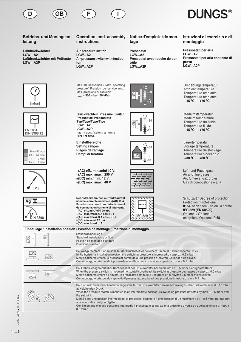
Betriebs-undMontagean-
leitung
Differenzdruckwächter für Luft,
Rauch- und Abgase
GGW … A4
Doppeldruckwächter
GGW … A4/GGW … A4
Operation and assembly
instructions
Differential pressure switch for
air, flue and exhaust gases
GGW … A4
Double pressure switch
GGW … A4/GGW … A4
Noticed'emploietdemon-
tage
Pressostat différentiel pour air,
fumée et gaz brûlés
GGW … A4
Pressostat double
GGW … A4/GGW … A4
Max. Betriebsdruck
Max. operating pressure
Pression de service maxi.
Max. pressione di esercizio
pmax. = 500 mbar
Druckwächter/ Pressure Switch/
Pressostat/ Pressostato
Typ/Type/Type/Tipo
GGW…A4, GGW…A4/2
nach / acc. / selon / a norme
DIN EN 1854
Umgebungstemperatur
Ambient temperature
Température ambiante
Temperatura ambiente
–15 °C … +70 °C
Mediumstemperatur
Medium temperature
Température du fluide
Temperatura fluido
–15 °C … +70 °C
Lagertemperatur
Storage temperature
Température de stockage
Temperatura stoccaggio
–30 °C … +80 °C
Schutzart / Degree of protection
Protection / Protezione
GGW…A4
IP 54 nach / acc. / selon / a norme
IEC 529 (EN 60529)
GGW…A4/2
IP 65 nach / acc. / selon / a norme
IEC 529 (EN 60529)
~(AC) eff., min./mini 24 V,
~(AC) max. /maxi. 250 V
=(DC) min./mini. 24 V,
=(DC) max. /maxi. 48 V
Einstellbereiche
Setting ranges
Plages de réglage
Campi di taratura
Standardeinbaulage
Standard installation position
Position de montage standard
Posizione standard
Bei waagerechtem Einbau schaltet der Druckwächter bei einem um ca. 0,5 mbar höheren Druck.
In the horizontal installation position the switching pressure is increased by approx. 0.5 mbar.
Monté horizontalement, le pressostat commute à une pression d´environ 0,5 mbar plus élevée.
Con montaggio orizzontale il pressostato scatta ad pressione superiore di circa 0,5 mbar.
Bei Einbau waagerecht über Kopf schaltet der Druckwächter bei einem um ca. 0,5 mbar niedrigerem Druck.
When the pressure switch is mounted horizontally overhead, its switching pressure decreases by approx. 0.5 mbar.
Monté horizontalement à l´envers, le pressostat commute à une pression d´environ 0,5 mbar moins élevée.
Con montaggio orizzontale capovolto il pressostato scatta ad una pressione inferiore di circa 0,5 mbar.
BeiEinbauineinerZwischeneinbaulageschaltetderDruckwächterbeieinemvomeingestelltenSollwertmaximal±0,5mbar
abweichenden Druck.
When the pressure switch is mounted in an intermediate position, its switching pressure deviates by max. ±0.5 mbar from
the setpoint.
Monté dans une position intermédiaire, le pressostat commute à une pression d'un maximum de +/- 0,5 mbar par rapport
à la valeur de consigne réglée.
Con il montaggio in una posizione intermedia il pressostato scatta ad una pressione diversa da quella nominale di max. ±
0,5 mbar.
Einbaulage / Installation position / Position de montage / Posizione de montaggio
α
Istruzioni di esercizio di
montaggio
Pressostato differenziale per
aria, gas di combustione e di
scarico
LGW … A4
Pressostato doppio
LGW … A4/LGW … A4
Nennstrom/nominal current/courant
nominal/corrente nominale ~(AC) 10 A
Schaltstrom/currentoncontact/courant
de commutation/corrente di intervento
~(AC) eff., min./mini 20 mA,
~(AC) max./maxi. 6 A cos ϕ = 1
~(AC) max./maxi. 3 A cos ϕ = 0,6
=(DC) min./mini. 20 mA
=(DC) max./maxi. 1 A
D I
GB F
[mbar]
2,5 – 50 mbar
0,4 – 3 mbar
30 – 150 mbar
1 – 10 mbar
[ V ]
Ag
[A]
DIN 3398
°C
0
+70
-15
°C
0
+70
-15
°C
0
+80
-30
IEC 529IEC 529
EN 1854
2 … 6
M/CD • Edition 08.00 • Nr. 239 364
G 1/4
7 Nm
Einbaumaße / Dimensions / Cotes d'encombrement / Dimensioni [mm]
Einbaumaße / Dimensions
Cotes d'encombrement / Dimensioni [mm]
GGW … A4 / GGW … A4, IP 54
Zusammenbauset Doppeldruckwächter
Double pressure switch: Side-By-Side Mounting Kit
Kit de montage pour pressostat double
Set di montaggio per il pressostato doppio
GGW … A4 / GGW … A4, IP 54
Bestell-Nr.
Order-No.
Réf. de commande
Nr. codice
213 910
1,2 NmM 4
2,5 Nm
DN
Rp
Mmax.
Tmax.
[Nm] t ≤10 s
[Nm] t ≤10 s
Gerät darf nicht als Hebel be-
nutzt werden
Do not use unit as lever.
Ne pas utiliser le pressostat
comme un levier.
L'apparecchionondeveessere
usato come leva.
max. Drehmomente / Systemzubehör
max. torque / System accessories
max. couple / Accessoires du système
max. coppie / Accessorio di sistema
Geeignetes Werkzeug einsetzen!
Please use proper tools!
Utiliser des outils adaptés!
Impiegare gli attrezzi adeguati!
Drehmoment Haubenschraube
max. torque cap-head screw
Couple max. pour les vis du couvercle
Coppia max. per vite a cappuccio
21
23
Chrome Steel ✸Made in Germany
8
1/4
35
20
6
1/8
25
15
Sechskantmutter M5 ISO 10511
M5 hex. nut, ISO 10511
Ecrou M5 ISO 10511
Vite esagonale M5 ISO 10511
Innensechskantschraube M5 x 12, ähnlich ISO 4762
M5 x 12 hex. socket bolt (ISO 4762)
Vis six-pans creux M5 x 12, similaire à ISO 4762
Vite esagonale interna M5 x 12, simile ISO 4762
G 1/4
G 1/4
O-Ring Ø 14,3 x 2,4
O ring Ø 14.3 x 2.4
Joint torique Ø 14,3 x 2,4
O-Ring Ø 14,3 x 2,4
Sechskantmutter M5 ISO 10511
M5 ISO 10511 hex. nut
Ecrou M5 ISO 10511
Vite esagonale M 5 ISO 10511
Druckanschluß G 1/4
G 1/4 pressure connection
Raccordement au fluide G 1/4
Attacco pressione G 1/4
4 x Ø 4,2 für Schrauben/for screws
pour vis/per vite M4 ISO 1207,4762
Innensechskantschraube M5 x 12, ähnlich ISO 4762
M5 x 12 socket head screw, similar to ISO 4762
Vis à six pans creux M5 x 12, similaire à ISO 4762
Vite esagonale interna M5 x 12, simile ISO 4762
Verschlußschraube G 1/4
G 1/4 screw plug
Bouchon G 1/4
Tappo di chiusura G 1/4
152
G 1/4
G 1/4
Druckanschluß G 1/4
G 1/4 pressure connection
Raccordement au fluide G 1/4
Attacco pressione G 1/4
Meßstutzen, integriert
Measurement nozzle, integrated
Prise de pression intégrée
Presa pressione integrata
O-Ring 14,3 x 2,4
14.3 x 2.4 o ring
Joint torique 14,3 x 2,4
O-ring 14,3 x 2,4
PG 11
oder Steckverbindung
PG 11 or connector
Raccordement électrique par PG 11 ou connecteur
PG 11 oppure collegamento a spina
57
37,4
10,3
18,5
Ø 2,5 x 9 tief für Gerätestecker DIN 43 650 A
2.5 x 9 dia. deep for DIN 43 650 A equipment plug
Ø 2,5 x 9 de profond pour embase de connecteur DIN 43 650 A
foro per spina Ø 2,5 x 9 DIN 43 650 A
Meßstutzen, integriert
Measurement nozzle, integrated
Prise de pression intégrée
presa pressione, integrata
Made in Germany
4 X Ø 4,2
für Schrauben M4 ISO 1201, ISO 4762
for M4 ISO 1201, ISO 4762 screws
pour vis M4 ISO 1201, ISO 4762
per viti M4 ISO 1201, ISO 4762
Druckanschluß G 1/4
G 1/4 pressure connection
Raccordement du fluide G 1/4
attacco pressione G 1/4
76
53,75 (LK 76)
72
G 1/4
SW 19
SW 21
Druckanschluß G 1/8
G 1/8 pressure connection
Raccordement du fluide G 1/8
attacco pressione G 1/8
[Nm]
18
19
Chrome Steel ✸Madein Ger many
➟
➟
M
max.
M
max.
T
max.
GGW…A4, IP 54
4 selbstfurchende Zylinderschrauben M3x14 Längsschlitz 0,8 und Kreuzschlitz DIN 7962-Z2
4 self-tapping cylinder bolts M3x14 slot 0.8 and cross slot to DIN 7962-Z2
4 vis auto-taraudeuses à tête cylindrique M3x14
tête fendue 0,8 et empreinte cruciforme DIN 7962-Z 2
Quattro viti a testa cilindrica autofilettanti M3 x 14
Intaglio longitudinale 0,8 e intaglio a croce DIN 7962-Z 2
36,4
65
10,3
Meßstutzen / test nipple / Prise
de pression/Nipplo di misurazione
Stopfen für G 1/4 - Druckanschluß / G 1/4 screw cap with sealing ring
Bouchon fileté G 1/4 avec bague d'étanchéité
Tappo a vite G 1/4 con guarnizione
Verschlußschraube mit Längsschlitz 1,0 Kreuzschlitz DIN 7962-Z 2
screw cap with slot 1.0 cross slot to DIN 7962-Z2
Bouchon fileté à tête fendue 1,0 empreinte cruciforme DIN 7962-Z 2
Vite di chiusura con intaglio longitudinale 1,0 intaglio a croce DIN 7962-Z 2
Verschlußschraube G 1/4 mit Dichtring
plug for G 1/4 pressure connection
Bouchon pour raccord de pression G 1/4
Tappo per attacco pressione G 1/4
G 1/4
+
77
53,75
ø 4,2 - 0,2
110
Druckanschluß G 1/4
Gas oder Luft
G 1/4 pressure connection
gas or air
Raccord de pression G 1/4
Gaz ou air
Attacco pressione G 1/4
gas oppure aria
38,5
2
1
3
3 … 6
M/CD • Edition 08.00 • Nr. 239 364
21
23
Chrome Steel ✸Made in Germany
Einbau
GGW…A4
1. DerDruckwächterwirddirektauf
einen Rohrstutzen mit R 1/4
Außengewinde aufgeschraubt.
Bild 1.
2. Nach Einbau Dichtheits- und
Funktionskontrolledurchführen.
AufvibrationsfreienEinbau
achten! Bild 2.
1
Installation of
GGW…A4
1. Screw the pressure switch di-
rectly on a tube socket with R 1/
4 outer thread (see Fig. 1).
2. Afterinstallation,performaleak-
age and function test.
Ensure that the pressure
switch is installed free of
vibration (see Fig. 2).
Montage
GGW…A4
1. Le pressostat peut se visser di-
rectementsurun piquageR 1/4"
Fig.1.
2. Après le montage contrôler la
jonction et l'étanchéité.
Veilleràcequel'appareilne
subisse pas de vibrations !
Fig. 2.
Montaggio
GGW…A4
1. Il pressostato viene avvitato di-
rettamente su un tubo di soste-
gno con filetto esterno R 1/4
(Fig.1)
2. Dopo il montaggio effettuare i
controlli di tenuta e funzionalità.
Evitare possibilità di vibra-
zioni! Fig 2.
2
Geeignetes Dicht-
mittel einsetzen!
Usepropersealing
compounds!
Utiliser une pâte à
joint adaptée!
Impiegare materia-
leditenutaadegua-
to!
4 … 6
M/CD • Edition 08.00 • Nr. 239 364
Elektrischer Anschluß
Electrical connection
Raccordement électrique
Allacciamento elettrico
IEC 730-1 (VDE 0631 T1)
PG 11
DIN 43 650 A
Schaltfunktion
Switching function
Schéma de fonctionnement
Funzione di commutazione
pressostato
GGW … A4
Erdung nach örtlichen Vor-
schriften.
Grounding acc. local regulations.
Miseàlaterreselonnormeslocales.
Messaaterrasecondo prescrizioni
locali.
Zur Erhöhung der Schaltlei-
stung wird bei DC-Anwendun-
gen < 20 mA und 24 V der
EinsatzeinesRC-Gliedesemp-
fohlen.
To increase the switching ca-
pacity,werecommendthatyou
use a RC device for current
values < 20 mA and 24 V d.c.
applicatins.
Pour augmenter la puissance
derupture, l'utilisationd'un cir-
cuitRCestpréconiséepourles
applicantions à courant conti-
nu < 20 mA et 24 V.
Per aumentare la potenza d'in-
serimentoconapplicazioniDC
< 20 mA e 24 V, consigliamo
l'impiego di un elemento RC.
Bei steigendem Druck:
1 NC öffnet, 2 NO schließt.
Bei fallendem Druck:
1 NC schließt, 2 NO öffnet.
While pressure is increasing:
1 NC opens, 2 NO closes.
While pressure is decreasing:
1 NC closes, 2 NO opens.
Pression montante:
1 NC ouvre, 2 NO ferme.
Pression descendante:
1 NC ferme, 2 NO ouvre
Con pressione in salita:
1 NC apre, 2 NO chiude.
Con pressione in discesa:
1 NC chiude, 2 NO apre
NO NC
2 1
3
COM
1 NC
2 NO
3 COMN
N
auf anfrage
on request
sur demande
su richiesta
p
COM NO
NC
2
1
3
Druckanschluß
Pressure port
Prise de pression
Attacco pressione
1Druckanschluß G 1/4 (+) für
Gas und Luft
1Pressureport G1/4(+)forgas
and air
1Prise de pression G 1/4 (+)
pour gaz et air
1Attacco pressione G 1/4 (+)
per gas ed aria
2Druckanschluß G 1/8 (–) für
Gas und Luft
2PressureportG1/8(-) forgas
and air
2Prise de pression G 1/8 (-)
pour gaz et air
2Attacco pressione G 1/8 (–)
per gas ed aria
G 1/4
12
➞ ➞ ➞ ➞
➞ ➞ ➞ ➞
➞ ➞ ➞ ➞
Gas Gaz
EN161
Familie 1 + 2 + 3
Family 1 + 2 + 3
Famille 1 + 2 + 3
Famiglia 1 + 2 + 3
➞ ➞ ➞ ➞
➞ ➞ ➞ ➞
➞➞ ➞➞
➞ ➞ ➞ ➞
➞ ➞ ➞ ➞
➞➞ ➞➞
Luft, Rauch- und Abgase
Air,flueandexhaustgases
Air, fumée et gaz brûlés
Aria, gas di combustione
e di scarico
➞ ➞ ➞ ➞
➞ ➞ ➞ ➞
➞➞ ➞➞
➞ ➞ ➞ ➞
➞ ➞ ➞ ➞
➞➞ ➞➞
Luft, Rauch- und Abgase
Air,flueandexhaustgases
Air, fumée et gaz brûlés
Aria, gas di combustione
e di scarico
5 … 6
M/CD • Edition 08.00 • Nr. 239 364
Réglage des pressostats
Enleverlesvisducapotenutilisant
un tournevis No3. PZ 2, Fig 1. En-
lever le capot.
Laprotectionn'estpasga-
rantie, contact avec des
pièces sous tension possible.
Regolazionedelpressostato per
Smontare la calotta con un at-
trezzoadeguato, ossiacacciavite
nr. 3 - rispettiv, PZ 2, figura 1
Togliere la calotta.
Nonésostanzialmentega-
rantita la protezione da
scariche, é possibile il contatto
con conduttori di tensione.
Réglage de GGW … A4
Réglerlepressostatavecsonbou-
ton gradué ❚à la valeur désirée
Fig. 2.
Respecterlesrecommandations
du constructeur du brûleur!
Le pressostat commute par pres-
sion montante: régler sur la ligne
de limitation gauche ↑❚. Le pres-
sostatcommuteparpressiondes-
cendante: régler sur la ligne de
limitation droite ❚↓. Remonter le
capot!
Regolazione GGW … A4
Tarare il pressostato, come in fi-
gura 2, sul valore di pressione
nominale prescritto, agendo sulla
rotella della scala graduata ❚.
Prestareattenzionealleprescri-
zioni del produttore del brucia-
tore!
Il pressostato scatta con pressio-
neinsalita:regolazionesullalinea
didelimitazionesinistra↑❚.Ilpres-
sostato scatta con pressione in
discesa:regolazionesullalineadi
delimitazione destra ❚↓. Rimonta-
re la calotta!
Einstellung des Druckwächters
Haube mit geeignetem Werkzeug
demontieren, Schraubendreher
No. 3 bzw. PZ 2, Bild 1.
Haube abnehmen.
Berührschutz ist nicht
grundsätzlich gewährt,
Kontakt mit spannungsführen-
den Teilen möglich.
Setting the pressure switch
Dismount the hood using a suita-
ble tool, e.g. screwdriver no. 3 or
PH1, Fig. 1. Remove hood.
There is no protection
against accidental con-
tact. Contact with live parts is
possible.
Einstellung GGW … A4
Druckwächter am Einstellrad mit
Skala ❚auf vorgeschriebenen
Drucksollwert einstellen, Bild 2.
Anleitung des Brennerherstel-
lers beachten!
Druckwächterschaltetbeisteigen-
dem Druck: Einstellung auf die
linke Begrenzungslinie↑❚.
Druckwächter schaltet bei fallen-
dem Druck: Einstellung auf die
rechte Begrenzungslinie ❚↓.
Haube wieder aufsetzen!
Setting GGW … A4
Set the pressure switch at the set-
ting wheel ❚to the specified pres-
sure setpoint using the scale, Fig.
2.
Follow the instructions of the
burner manufacturer!
Pressureswitchswitchesaspres-
sureincreases:Set toleft limit line
↑❚. Pressure switch switches as
pressurereduces:Settorightlimit
line ❚↓.
Remount hood!
1
Ersatzteile / Zubehör
Spare parts / Accessories
Pièces de rechange / access.
Parti di ricambio / Accessori
Haube komplett / IP 54
Hood kit, IP 54
Kit couvercle, IP 54
Set calotta, IP 54
Verschlußschraube G 1/4 mit
Dichtring
Screw plug Rp 1/4 with
sealing ring
Bouchon G 1/4 avec joint
Tappo a vite G 1/4 con
anello di tenuta
Bestell-Nummer
Ordering No.
No. de commande
Codice articolo
230 275
230 396
Ersatzteile / Zubehör
Spare parts / Accessories
Pièces de rechange / access.
Parti di ricambio / Accessori
Zusammenbauset Doppel-
druckwächter, IP 54
Double pressure switch: Side-
By-Side Mounting Kit, IP 54
Kitdemontagepourpressostat
double, IP 54
Set di montaggio per il presso-
stato doppio, IP 54
Leitungsdose 3 pol. + E
grau, GDMW
Power socket, 3-pole + E
grey, GDMW
Connecteur gris 3 pôles + terre
Presa di corrente a 3 poli +
terra, grigia, GDMW
Bestell-Nummer
Ordering No.
No. de commande
Codice articolo
213 910
210 318
2
Made in Germany
0,4
2,1
0,6
0,9
1,2
1,5
1,8
2,4
2,7
3
mbar
LGW 3 A4
pmax. 500 mbar
~(AC) 10 A 250 V
CE-0085 AQ 0673
↑↓
6 … 6
M/CD • Edition 08.00 • Nr. 239 364
Karl Dungs GmbH & Co.
Siemensstr. 6-10
D-73660 Urbach
Telefon +49 (0)7181-804-0
Telefax+49(0)7181-804-166
Verwaltung und Betrieb
Head Offices and
Factory Usine et
Services Administratifs
Amministrazione e
Stabilimento
Korrespondenzanschrift
Postal address
Adresse postale
Indirizzare la corrispon-
denza a
Karl Dungs GmbH & Co.
Postfach 12 29
D-73602 Schorndorf
e-mail [email protected]
Internetwww.dungs.com
Änderungen, die dem technischen Fortschritt dienen, vorbehalten / We reserve the right to make alterations in the course of technical improvement
Sous réserve de toute modification constituant un progrès technique / Ci riserviamo qualsiasi modifica tecnica e costruttiva
Rohrleitungsdichtheits-
prüfung: Kugelhahn
vor
demDruckwächterschlie-
ßen.
Nach Abschluß von Ar-
beiten am Druckwächter:
Dichtheitskontrolle und
Funktionskontrolledurch-
führen.
Niemals Arbeiten durch-
führen, wenn Gasdruck
oder Spannung anliegt.
OffenesFeuervermeiden.
Örtliche Vorschriften be-
achten.
Bei Nichtbeachtung der
Hinweise sind Personen-
oder Sachfolgeschäden
denkbar.
Pipelineleakagetest:clo-
se ball valve upstream
of the pressure switch.
On completion of work
on the pressure switch,
perform a leakage and
function test.
Neverperformworkifgas
pressure or power is ap-
plied. No naked flame.
Observe local regulat-
ions.
If these instructions are
notheeded,theresultmay
be personal injury or da-
mage to property.
Encas denon-respectde
ces instructions, des
dommages corporels ou
matériels sont possible.
Ne jamais effectuer des
travaux sous pression et
ou sous tension. Eviter
toute flamme ouverte.
Observerlesréglementa-
tions.
Unefoislestravauxsurle
pressostatterminés,pro-
céder toujours à un con-
trôle d'étanchéité et de
fonctionnement.
Contrôle de l'étanchéité
de la conduite: fermer le
robinet à boisseau sphè-
rique
avant
lepressostat.
Perla prova ditenuta del-
le tubature:
chiudereilrubinettoasfe-
ra
davanti
alpressostato.
Alterminedeilavorieffet-
tuati su un pressostato:
predisporre un controllo
sia della tenuta che del
funzionamento.
Innessun caso sidebbono
effettuare lavori in presen-
za di pressione gas o di
tensione elettrica. Evitare i
fuochiapertie osservarele
prescrizioni di sicurezza
locali.
La non osservanza di
quanto suddetto può im-
plicare danni a persone o
cose.
Kondensat darf nicht in
das Gerät gelangen. Bei
Minustemperaturen,
durch Vereisung Fehl-
funktion/Ausfallmöglich.
Eviterl'entréedeconden-
sat dans le pressostat,
une prise en glace par
températurenégativenui-
raitàsonfonctionnement.
Do not allow condensate
toflowintotheequipment.
In case of sub-zero tem-
peratures, malfunction or
equipment failure may be
possible due to icing.
nell' apparecchio non
deveinfiltrarsialcunacon-
densa. Alle temperature
negative sarebbero pos-
sibilidisfunzioni dovutea
formazione di ghiaccio.
Arbeiten am Druckwäch-
ter dürfen nur von Fach-
personal durchgeführt
werden.
Seul du personnel spé-
cialisépeuteffectuerdes
travauxsurlepressostat.
Work on the pressure
switch may only be per-
formedbyspecialiststaff.
Qualsiasi operazione
effettuatasul pressostato
deveesserefattadaparte
dipersonalecompetente.
Safety
first
O.K.

Other manuals for GW A4 Series

4

Other Dungs Switch manuals

Dungs LGW A1 Series Service manual

Dungs

Dungs LGW A1 Series Service manual

Dungs GGAO-A4-4 User manual

Dungs

Dungs GGAO-A4-4 User manual

Dungs LGW A2 Series User manual

Dungs

Dungs LGW A2 Series User manual

Dungs LGW A2 SGN Series User manual

Dungs

Dungs LGW A2 SGN Series User manual

Dungs GGW A4/2 X Series User manual

Dungs

Dungs GGW A4/2 X Series User manual

Dungs KS A2-7 Series User manual

Dungs

Dungs KS A2-7 Series User manual

Dungs GW A2 Series User manual

Dungs

Dungs GW A2 Series User manual

Dungs AA-A1-0 Series User manual

Dungs

Dungs AA-A1-0 Series User manual

Dungs AA C2 Series User manual

Dungs

Dungs AA C2 Series User manual

Dungs GW A4 HP SGS Series User manual

Dungs

Dungs GW A4 HP SGS Series User manual

Dungs LGW A2 SGN Series User manual

Dungs

Dungs LGW A2 SGN Series User manual

Dungs LGW A4 SGV Series Service manual

Dungs

Dungs LGW A4 SGV Series Service manual

Dungs LGW A2 Series Service manual

Dungs

Dungs LGW A2 Series Service manual

Dungs GGW A4 Series User manual

Dungs

Dungs GGW A4 Series User manual

Dungs GW A4 HP SGS Series User manual

Dungs

Dungs GW A4 HP SGS Series User manual

Dungs CPI 400 User manual

Dungs

Dungs CPI 400 User manual

Dungs GW A6 Series User manual

Dungs

Dungs GW A6 Series User manual

Dungs GW A4 Series User manual

Dungs

Dungs GW A4 Series User manual

Dungs GW   500 A4/2 HP X Service manual

Dungs

Dungs GW 500 A4/2 HP X Service manual

Dungs GW A2 Series User manual

Dungs

Dungs GW A2 Series User manual

Dungs GW A4/2 HP X Series User manual

Dungs

Dungs GW A4/2 HP X Series User manual

Dungs GW A4 Series User manual

Dungs

Dungs GW A4 Series User manual

Dungs LGW A2 Series Service manual

Dungs

Dungs LGW A2 Series Service manual

Dungs GW A6 Series Service manual

Dungs

Dungs GW A6 Series Service manual

Popular Switch manuals by other brands

Chamberlain RZ94-05 instruction manual

Chamberlain

Chamberlain RZ94-05 instruction manual

Extron electronics SW4 ARxi user guide

Extron electronics

Extron electronics SW4 ARxi user guide

KVMSwitchTech KVMSWR-2X16IP installation guide

KVMSwitchTech

KVMSwitchTech KVMSWR-2X16IP installation guide

Autonics ARIO-C-MT manual

Autonics

Autonics ARIO-C-MT manual

Lumantek ez-Pro VS10 manual

Lumantek

Lumantek ez-Pro VS10 manual

TP-Link TL-SF1005D installation guide

TP-Link

TP-Link TL-SF1005D installation guide

Kappa WST-916 Operation manual

Kappa

Kappa WST-916 Operation manual

Linksys EG0008 - EtherFast Switch user guide

Linksys

Linksys EG0008 - EtherFast Switch user guide

Mellanox Technologies TX6100 MetroX Series Hardware user manual

Mellanox Technologies

Mellanox Technologies TX6100 MetroX Series Hardware user manual

ESYLUX CDSi-A/N instructions

ESYLUX

ESYLUX CDSi-A/N instructions

UTEPO UTP3306S-PSB user manual

UTEPO

UTEPO UTP3306S-PSB user manual

Wöhner CAPUS CP-S32-630/3P manual

Wöhner

Wöhner CAPUS CP-S32-630/3P manual

Panasonic AV-HS6000 Operation guide

Panasonic

Panasonic AV-HS6000 Operation guide

CP TECHNOLOGIES GSW-2457 Quick installation guide

CP TECHNOLOGIES

CP TECHNOLOGIES GSW-2457 Quick installation guide

Ruijie Reyee RG-ES105D Series Hardware  installation and reference guide

Ruijie

Ruijie Reyee RG-ES105D Series Hardware installation and reference guide

D-Link DGS-1052X Quick installation guide

D-Link

D-Link DGS-1052X Quick installation guide

Cisco SRW224P - 10/100 - Gigabit Switch user guide

Cisco

Cisco SRW224P - 10/100 - Gigabit Switch user guide

NTI RACKMUX-V15-4UNV Installation and operation manual

NTI

NTI RACKMUX-V15-4UNV Installation and operation manual

manuals.online logo
manuals.online logoBrands
  • About & Mission
  • Contact us
  • Privacy Policy
  • Terms and Conditions

Copyright 2025 Manuals.Online. All Rights Reserved.