CHOWEL TB40-P02A User manual


----- Important -----
Read first this manual before operate this device. In some case, failure to follow this manual
can lead to control or machine damage. In other cases failure to follow instructions can lead
to injury, or death of personnel.
This manual explains some instructions depends on the level of danger as follows.
DANGER
It shows readers where people will be hurt if procedures are not followed properly.
WARNING
It shows readers where people may be hurt if procedures are not followed properly.
CAUTION
It shows readers where machinery may be damaged or economic loss can occur ,or people
may be hurt if procedures are not followed properly.
It shows risk of electric shock.
It shows toxic risk.
It shows risk of catching his/her finger in the door.
It shows risk of fire.
It shows risk of explosion.
It shows risk of burn.
It shows risk of injury by the revolving parts.
It shows prohibition of analyzing.
It shows to be sure to connect grounding wire.
It shows to be sure to pull the power plug.
It shows mandatory action.

READ FIRST
To use this device in safety, he/she should follow industry standards and safety senses
whenever working on, or near the weld machine.
In some case, failure to follow the warning instructions can lead to damage. In other cases
failure to follow these instructions can lead to injury, or death of personnel.
Some examples of safe practices are listed below. These examples are not to be considered a
comprehensive listing of safety practices. Always use safety senses when working with any
type of machinery.
DANGER
1. Turn electrical power OFF, if it is necessary to open the door of the controller
when joint or remove a communication cable. Opening the door without turning
power off can lead to injury by an electric shock, or death of personnel.
Always use safety senses even if the he/she is able to work on without open the door.
2. Wiring the communication cable with catching under the machine etc. can lead
to damage and short. And remove the communication cable with taking the
connector with his/her fingers, whenever remove the cable. Do not stretch a
wires. Stretching the wires can lead to wires damage and short.
And short or damage of the wires may occur a fire or an electric shock.
WARNING
1. Cables should not be run to be damaged by other machinery. Catching foot on cable can
leads to an injury of personnel.
2. In using or storing, this device should be protected from direct sunshine, much dust, water
and high humidity.
3. This device is not put on high or unstable place. Falling down of the device can lead to a
damage and an injury.
4. Operator never operate this device. And maintenance person do not allow operator to
operate this device.
CAUTION
1. Communication cable is jointed to the controller perfectly and correctly.
2. Do not analyze, alter and repair this device.
3. If cleaning this device with thinner or benzine etc., device case may deform or fade.

Preface
This teaching box is designed to obtain CE marking and is based on following standards.
[EN50011-2], [EN50082-2]
[EN60204-1], [EN61000-4-2], [EN61000-4-4], [EN61000-4-5], [EN61000-4-8],
[ENV50140], [ENV50141] etc.
TB40
!WARNING
a. Understand fully this manual before you attend to work.
b. Keep this manual in decided place in order to read this manual easily and regularly.
c. Order new manual from NADEX Co., Ltd. when you lost and damaged this manual.
d. When you transfer this device, transfer this manual to next owner, too.

Contents
1. Outline
2. Notes to Handling
3. Description of Each Part
4. Normal Display
5. Error / Fault Display
6. Function Select Modes
6-1. Function Select
6-2. Teaching Mode Change
6-3. Data Name / Data Range Change
6-4. Backlight ON/OFF Change
6-5. Data Copy
6-6. Reset Various Functions
6-7. Data Initialize
6-8. Schedule duplicate
6-9. Timer Slave Station No. Confirm / Change mode
6-10. Input / Output Monitor
6-11. Device Net Setting
6-12. CC Link Setting
6-13. Ether Net Setting
6-14. Profibus Setting
6-15. Date / Time Confirm / Change Mode.
6-16. Write Collectively
6-17. Error history
7. Other Functions
7-1. In case of stopping writing
7-2. In case of continuing writing

1. Outline
The teaching box is option for welding controller.
The teaching box has features as follows:
- Display / input of program data in a spread sheet format.
- Function select in menu.
Data copy function, various counter data clear functions, etc.
- Error alarm with buzzer sound.
- LCD (Liquid Crystal Display) with backlight for use in the dark.
2. Notes to Handling
- Do not use the teaching box for any other welding controller than corresponding.
- Be careful not to drop the teaching box to a hard object or apply a strong shock to teaching
box.
- Do not leave the teaching box under direct sunlight.
- Do not use the teaching box where it is exposed to water splash.
- Do not use the teaching box where it is exposed to a large amount of dust, dirt, spatter, etc..
(Particularly, do not attach / detach the connectors in such atmosphere.)
- If the teaching box does not operate or indicate anything, please perform the following
things.
a. Turn off a power supply for welding controller.
b. Check whether there is any short circuit of a connector part.
c. After a while, turn on a power supply for welding controller again.
For details, please refer to a manual of a welding controller.
- There is also a function in which it does not correspond depending on the soft version of a
teaching box.

3. Description of Each Part
(1) Attaching / detaching connectors
(2) LCD window
If the teaching box is not operated for about 3 minutes or there is no error caused for about 3
minutes, the backlight will be automatically turned OFF. If some key is hit then, the
backlight will be turned ON again.
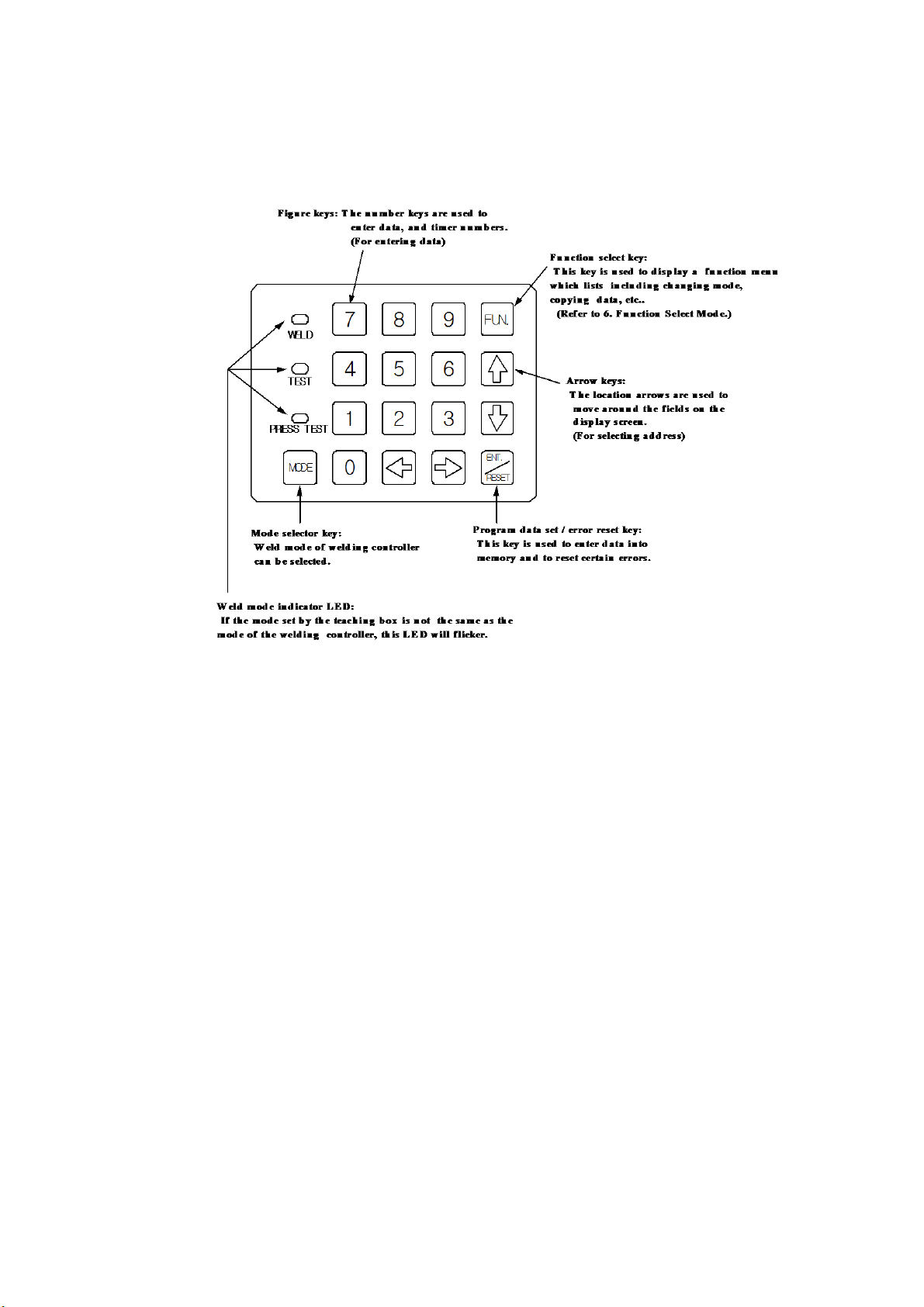
(3) Keyboard
Figure keys : Input data keys
Arrow keys : Select address keys
Instruction of each mode operation
WELD OPERATION : Sequence is active and weld.
TEST : Sequence active and not weld. (At installation)
PRESS TEST : There is no sequence operation but there is only turning ON/OFF of the
VALVE OUTPUT in accordance with ON/OFF of the PILOT INPUT. (No welding)

4. Normal Display
After the power supply for the welding controller is turned ON, or after the teaching box is
connected, the LCD display appears as shown in Fig. 4-1.
Fig. 4-1
(1) SCHE 1 : This is a X address.
X addresses can be shifted by the ←, →keys.
(2) Y0, Y1 : These are Y addresses.
Y addresses can be shifted by the ↑, ↓keys.
If the ↑, ↓, ←, →keys are kept pressed, the address can be shifted faster.
(In this case, the data will be displayed as "- - - - " )
PROGRAM, MONITOR, etc. are divided into three groups-common, schedule, and stepper.
The X address at each address is displayed as follows. (○: schedule or stepper No.. "d","h" :
Only specific the welding controller. )
a. COMMON
b. STEPPER MON
c. COMMON MON
d. COMMON REC
e. SCHE ○○
f. STPR ○○
g. SCHE ○○ MON
h. SCHE ○○ REC
Direct Jump function
If ↑or ↓keys is double-clicked, Direct Jump setup in Y address is displayed.
If ←or →keys is double-clicked, Direct Jump setup in X address is displayed.
Input arbitrary address with a ten key and press ENT./RESET key.
(3) INIT. SQUEEZE TIME :
The address indicated by the cursor is displayed.
The contents is a data name or a data range that can be set.
(Refer to 6-3. Data Name / Data Range Change)
(4) : This indicates the data value.
(5) : This indicates the teaching mode.
"PROG" means the data input enable mode, and "noPRG" means the data input disable

mode.
(Refer to 6-2. Teaching mode change)
(6) : This indicates PILOT (START).
When "*" is shown, it means that the PILOT is ON.
(7) : This indicates the timer slave station number (TIMER No.).
This display is the hexadecimal 0 through F as a decimal 0 through 15.

5. Error / Fault Display
(1) Communication Error
This error is displayed as shown in Fig. 5-1.
Check the communication cable.
Fig. 5-1
(2) Other error / fault
Other error / fault is displayed as shown in Fig. 5-2 with the error code and the start schedule
No. to which the error is caused and the error description. (Fig. 5-2 shows an example of the
LOW VOLTAGE IN WELD error that was caused during weld operation to start schedule
No. 2.)
Press the ENT./RESET key ,and the error will be reset.
Fig. 5-2
If plural fault occurred at the same time, change to other fault display by ↑, ↓key.
Refer to the manual of a welding controller about the contents and the measure of error /
fault.

6. Function Select Modes
6-1. Function Select
Press the FUN. key, and the LCD display will turn to be as shown in Fig. 6-1-1.
Fig. 6-1-1
In this case, each keys has its own function as follows:
↑↓: Moves the cursor
ENT. /RESET : Executes the function indicated by the flickering cursor.
MODE : Changes the teaching mode.
→Refer to 6-2. Teaching Mode Change.
0 : Changes the data name / data range.
→Refer to 6-3. Data Name / Data Range Change.
1 : Changes the LCD backlight ON / OFF.
→Refer to 6-4. Backlight ON/ OFF Change.
2 : Changes the mode to the data copy mode.
→Refer to 6-5. Data Copy.
3 : Changes the mode to the reset modes.
→Refer to 6-6. Reset Various Functions.
4 : Initializes the data of the welding controller.
→Refer to 6-7. Data Initialize.
5 : Changes the mode to the schedule duplicate mode.
→Refer to 6-8. Schedule Duplicate.
6 : Changes the mode to the timer slave station No. confirm / change mode.
→Refer to 6-9. Timer Slave Station No. Confirm / Change Mode.
7 : Monitoring INPUT / OUTPUT.
→Refer to 6-10. INPUT / OUTPUT Monitor.
8 : Device Net Setting.
→Refer to 6-11. Device Net Setting.
9 : CC Link Setting.
→Refer to 6-12. CC Link Setting.
( Move by ↑or ↓key ): Ether Net Setting.
→Refer to 6-13. Ether Net Setting.
( Move by ↑or ↓key ): Profibus Setting.
→Refer to 6-14. Profibus Setting.
( Move by ↑or ↓key ): Date / Time Confirm / Change Mode.
→Refer to 6-15. Date / Time Confirm / Change Mode.
( Move by ↑or ↓key ): Write Collectively.
→Refer to 6-16. Write Collectively.
FUN. : Return to the display previous to the present display.
(Use this Key when a wrong key is pressed.)

Other keys than the above : Returns to the normal display.
6-2. Teaching Mode Change
As described in Fig. 4-1 (5), the teaching box is provided with the teaching mode which can be
divided further into the following two modes:
PROG : Program enable (data input enable) mode.
noPRG : Program disable (data input disable) mode.
To change these mode, use the following key strokes.
1. FUN.
2. MODE : Execute the mode change.
or
1. FUN.
2. ↑↓: Bring the cursor to "MODE=PROG.MODE CHANGE".
3. ENT./RESET : Execute the mode change.
The LCD display resumes the normal display.
If the status previous to this mode change is "PROG", the mode will turn to the "noPRG"
mode, and if it is "noPRG", the mode will turn to the "PROG" mode.
6-3. Data Name / Data Range Change
As described in Fig. 4-1 (3), the teaching box has the following two types of display.
Data name :
In the normal display, the name of the present address data is shown in the bottom line in
the LCD display.
Data range :
In the normal display, the range of the data that can be set to the present address is shown in
the bottom line in the LCD display.
To change the display, use the following key strokes:
1. FUN.
2. 0 : Execute the display change.
or
1. FUN.
2. ↑↓:Bring the cursor to "0=NAME/RANGE CHANGE".
3. ENT./RESET : Execute the display change.
The LCD display resumes the normal display.
If the status previous to this display change is the data name display, it will change to the
data range display, and if it is the data range display, it will change to the data name display.

6-4. Backlight ON/OFF Change
To change the backlight ON/OFF, use the following key strokes:
1. FUN.
2. 1 : Execute the ON/OFF change.
or
1. FUN.
2. ↑↓: Bring the cursor to "1=BACK LIGHT ON/OFF".
3. ENT./RESET : Execute the ON/OFF change.
The LCD display resumes to the normal display.
If the status previous to this ON/OFF change is the backlight ON, it will change to the
backlight OFF, and if it is the backlight OFF, it will change to the backlight ON.
6-5. Data Copy
To change the mode to this mode, use the following key strokes:
1. FUN.
2. 2 : Execute the mode change.
or
1. FUN.
2. ↑↓: Bring the cursor to "2=DATA COPY".
3. ENT./RESET : Execute the mode change.
Then, the LCD display will turn to be as shown in Fig. 6-5-1.
Fig. 6-5-1
(1) To copy data from the timer (welding controller) to the teaching box.
Press 1 key or bring the cursor to 1 in the display as shown in Fig. 6-5-1 and press
the ENT./RESET key, the LCD display will turn to be as shown in Fig. 6-5-2.
Fig. 6-5-2
The teaching box is possible to store the data of three type . Specify the number of the desired

data type and press the key of the number. If 2 key is pressed, for example, the LCD
display will turn to be as shown in Fig. 6-5-3.
Fig. 6-5-3
Press the ENT./RESET key, and the bottom line in the LCD display will turn to be as
shown in Fig. 6-5-4 and resume the normal display.
Fig. 6-5-4
(2) To copy data from the teaching box to the timer (welding controller).
Press 2 key or bring the cursor to 2 in the display as shown in Fig. 6-5-1 and press
the ENT./RESET key, the LCD display will turn to be as shown in Fig. 6-5-5.
Fig. 6-5-5
The teaching box is possible to store the data of three type . Specify the number of the desired
data type and press the key of the number. If 0 key is pressed, for example, the LCD
display will turn to be as shown in Fig. 6-5-6.
Fig. 6-5-6
The subsequent procedure is the same as (1) above excepting the case where the memory is
lost due to excessive backup period of the teaching box or the teaching box data is tried to
compared with the welding controller data when there is an error/fault, in which case the
display as shown in the bottom 2 lines two in Fig. 6-5-6 will turn to be as shown in Fig. 6-5-7.

Fig. 6-5-7
If some key is hit then, the normal display as shown in Fig. 6-1-1 will be resumed.
- Caution of copy function
(1) When copying from the T/B to the welding controller, the message "WRITE INHIBITED"
sometimes be showed. This indicate the data of the T/B is outside the range of the welding
controller data. In this case, please set all items one by one without the copy function.
If some key is hit then, the normal display as shown in Fig. 6-1-1 will be resumed.
(2) In case of a similar model, or case of carrying out a data copy at the time of the soft change
by upgrade, refer to 7. Other Functions.
(3) To compare data between the teaching box and the timer (welding controller).
Press 3 key or bring the cursor to 3 in the display as shown in Fig. 6-5-1 and press
the ENT./RESET key, the LCD display will turn to the display as shown in Fig. 6-5-8.
Fig. 6-5-8
The teaching box is possible to store the data of three type . Specify the number of the desired
data type and press the key of the number. If 1 key is pressed, for example, the LCD
display will turn to be as shown in Fig. 6-5-9.
Fig. 6-5-9
Press the ENT./RESET key, and comparison will start.
- When there is discrepancy between the data
The LCD display will turn to be as shown in Fig. 6-5-10. The schedule shown in this figure is
the schedule for discrepancy between the data. As the comparison is mode in the order of
Schedule No. 255, No. 254, No. 253, ... , if there is a schedule in which 2 or more data do not
agree with each other, only 1 schedule No. in which the discrepancy is found in the first place
will shown.

Fig. 6-5-10
If some key is hit then , the normal display as shown in Fig. 6-1-1 will be resumed.
- When there is no discrepancy between the data
The display in the bottom line as shown in Fig. 6-5-9 will turn to be as shown in Fig. 6-5-11.
Fig. 6-5-11
The display will remain for 1 second, and then the normal display will be resumed.
-When the teaching box backup data has an error
If the memory data is lost due to excessive backup period of the teaching box or the welding
controller data is tried to be compared when there is an error, the LCD display as shown in
the bottom 2 lines in Fig. 6-5-9 will turn to be as shown in Fig. 6-5-12.
Fig. 6-5-12
If some key is hit then, the normal display as shown in Fig. 6-1-1 will be resumed.

6-6. Reset Various Functions
To change the mode to the Reset Various Functions modes, use the following key strokes.
1. FUN.
2. 3 : Execute the mode change.
or
1. FUN.
2. ↑↓: Bring the cursor to "3=RESET VARIOUS FUNC."
3. ENT./RESET : Execute the mode change.
Then, the LCD display turns to be as shown in Fig. 6-6-1.
Fig. 6-6-1
The reset function has the following three types:
1 : Stepper reset
2 : Total weld counter reset
3 : Tact counter reset
(The reset function is different depending on the specific model.)
(1) To reset the stepper
Following the display of Fig. 6-6-1, Press the 1 key or bring the cursor to the line of 1
and press the
ENT./RESET key. The LCD display will turn to be as shown in Fig. 6-6-2.
Fig. 6-6-2
If you want to reset the all stepper, press the 0 key and ENT./RESET key.
If you want to reset the individual stepper, input the Stepper No. and press the ENT./RESET
key.
When ENT./RESET key is pressed, reset will be start.
After the reset ends, the bottom line in the LCD display will turn to be as shown in Fig. 6-6-3.
And the normal display will be resumed.
Fig. 6-6-3

If the Stepper No. not existing is inputted, LCD display will turn to be as shown in Fig. 6-6-4.
Press any key. The display as shown in Fig. 6-1-1 will be resumed.
Fig. 6-6-4
If 1 and 3 are pressed following the display of Fig. 6-6-2, it becomes as it is shown in
Fig. 6-6-5. In this case, a press of the ENT./RESET key resets only the Stepper No.13.
Fig. 6-6-5
Repeat the same work, when you reset some Stepper No..
Press the FUN. key, when you do not reset.
(2) To reset the total weld counter
Press the 2 key or bring the cursor to the line of 2 and press the ENT./RESET key. The
LCD display will turn to be as shown in Fig. 6-6-6.
Fig. 6-6-6
It will start, if an ENT./RESET key is pressed. After ending, the display of LCD becomes
as it is shown in Fig. 6-6-3, and the normal display will be resumed.
(3) To reset the tact counter
Press the 3 key or bring the cursor to the line of 3 and press the ENT./RESET key. The
LCD display will turn to be as shown in Fig. 6-6-7.
Fig. 6-6-7
It will start, if an ENT./RESET key is pressed. After ending, the display of LCD becomes
as it is shown in Fig. 6-6-3, and the normal display will be resumed.
6-7. Data Initialize
All the data written in the welding controller by teaching can be replaced by the initialize
data on the welding condition that is stored beforehand in the welding controller.

!CAUTION
About initialize data, refer to the instruction manual of welding controller.
To initialize the weld data, use the following key strokes.
1. FUN.
2. ↑↓: Bring the cursor to "4=DATA INITIALIZE".
3. ENT./RESET : The LCD display will turn to be as shown in Fig. 6-7-1.
Fig. 6-7-1
4. FUN. : Execute the data initialize.
or
1. FUN.
2. 4
3. ENT./RESET : Execute the data initialize.
After the execution, the normal display will be automatically resumed.
6-8. Schedule duplicate
To change the mode to the schedule duplicate mode, use the following key strokes.
1. FUN.
2. 5 : Execute the mode change.
or
1. FUN.
2. ↑↓: Bring the cursor to "5=SCHEDULE DUPLICATE".
3. ENT./RESET : Execute the mode change.
The LCD display will turn to be as shown in Fig. 6-8-1.
Fig. 6-8-1
The schedule No. previous to the schedule duplicate mode will be shown in (1) (when the
schedule No. is 0, "1" will be shown) together with the cursor, and nothing will be shown in
(2) and (3).
!CAUTION
Press any key other then the number keys and the ENT./RESET key, and the function
menu display will be resumed.
This manual suits for next models
2
Table of contents


