Elektron MULTIMIG 200 User manual

Made in Germany
Operation Manual
MULTIMIG 200
MIG / MAG - Welding machine
Item-No: 327 973
Revision: 1.0 - Original
Version: 31.01.2013
Be sure you have read and understood this o erating
manual before you carry out any works on and/or with this
equi ment!

2
© BlitzRotary GmbH
Bran h Bremen
Hinterm Sielhof 22
D-28277 Bremen
Germany
Phone: +49 (0)421 / 54 90 6 - 906
Fax: +49 (0)421 / 54 90 6 - 19
E-Mail: vertrieb@elektron-bremen.de
Internet: www.elektron-bremen.de
Release:
BlitzRotary GmbH Bran h Bremen

MULTIMIG 200
Table of contents
3
Table of contents
1
Machine elements 4
2
Ex lanation of symbols 5
2.1
Meaning of the symbols in the operation
manual 5
2.2
Meaning of the symbols on the ma hine 5
3
Safety recautions 5
4
General regulation of use 6
5
Unit rotection 6
6
Noise emission 6
7
Ambient conditions 7
8
UVV ins ection 7
9
Electromagnetic com atibility
(EMC) 7
10
Setu and trans ort 8
11
Brief o erating instructions 9
12
Before start-u 10
12.1
Conne ting the tor h 10
12.2
Conne ting the ground able 10
12.3
Fastening the ground lamp 10
12.4
Insert the welding wire spool 11
12.5
Thread the wire ele trode in 11
12.6
Conne ting the inert gas ylinder 12
12.7
Changing the wire ele trode 12
13
Start-u 14
13.1
Control onsole MULTIMIG 200 14
13.2
Start-up 15
13.3
Current / voltage display 16
13.4
Tor h with remote ontrol 16
13.5
Dea tivate operation mode 16
13.6
Chara teristi line 17
13.7
Mode Manual 17
13.8
Se ondary parameters 17
13.9
Tiptroni 18
13.10
Spe ial fun tions 21
13.11
Reset setting 21
14
Menu structure 23
15
Messages 25
16
Troubleshooting 26
17
Re air and maintenance 28
17.1
Che k regularly 28
17.2
Tor h are 28
18
Technical data 29
19
O tions and accessories 30
19.1
tor h holder 30
20
Dis osal 30
21
Service 30
22
Schematic 31
MULTIMIG 200
Machine elements
4
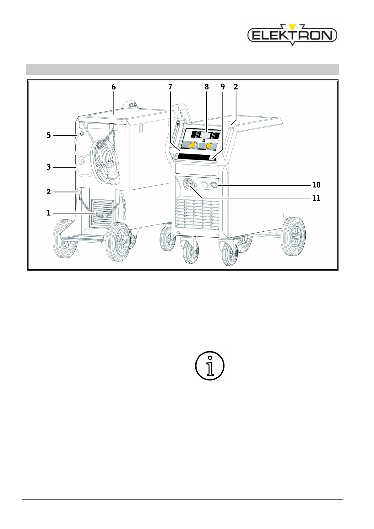
1 Machine elements
Fig. 1: Machine elements
1 Safety hain for gas
2 Hoisting points
3 Mains able
5 Gas hose
6 Tray area
7 Handle
8 Control panel
9 Main swit h
10 So ket for ground able
11 Central so ket
Some depi ted or des ribed a es-
sories are not in luded in the s ope
of delivery.
Subje t to hange.
MULTIMIG 200
Ex lantion of symbols – Safety recautions
5
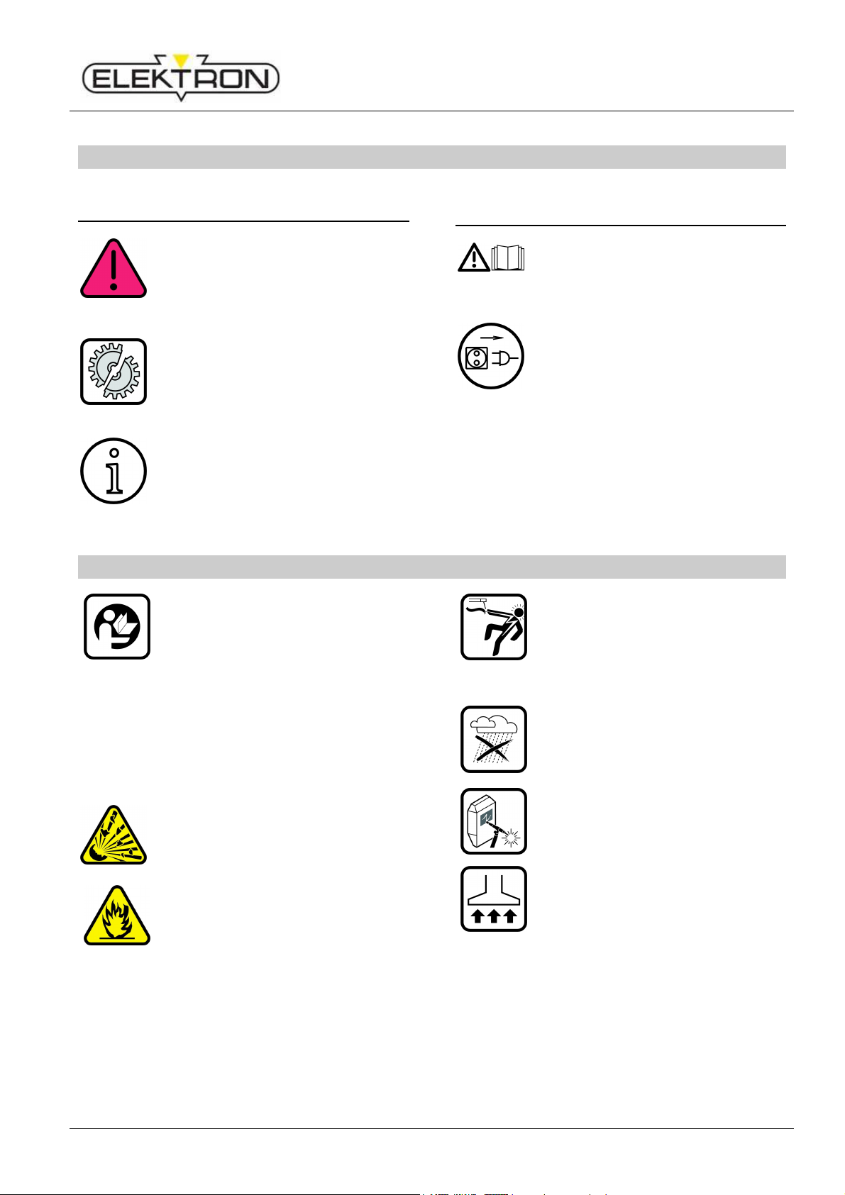
2 Ex lanation of symbols
2.1 Meaning of the symbols in the
o eration manual
Danger to life and limb!
If the danger warnings are disre-
garded, this an ause slight or
severe injuries or even death.
Danger of ro erty damage!
Disregarding danger warnings an
ause damage to work pie es,
tools, and equipment.
General note!
Designates useful information
about the produ t and equipment.
2.2 Meaning of the symbols on the
machine
Danger!
Read the user information in the
operation manual.
Disconnect the mains lug!
Pull out the mains plug before
opening the housing.
3 Safety recautions
Hazard-free working with the ma-
hine is only possible if you read
the operating and safety instru -
tions ompletely and stri tly ob-
serve them.
Please obtain pra ti al training be-
fore using the ma hine for the first
time. Follow the a ident preven-
tion regulations (UVV
1
)).
Before starting any welding work,
lear away any solvents,
degreasing agents, and other
flammable materials from the
working area. Cover flammable
materials whi h an not be moved.
Only weld if the ambient air
ontains no high on
entrations of
dus
t, a id vapours, gases or
flammable substan es. Spe ial
are must be taken during repair
work on pipe systems and tanks
whi h ontain or have on
tained
flammable liquids or gases.
Never tou h live parts inside or
outside of the housing. Never
tou h wel
ding ele trodes or live
welding urrent parts in a ma hine
that is on.
Do not expose the ma hine to
rain, do not spray water on it or
steam blast it.
Always use a welding shield. Warn
other persons in the welding area
about ar -rays.
Please use a suitable extra tion
system for gases and utting
fumes. Always wear breathing
apparatus whenever there is a
risk of inhaling welding or utting
vapours.
MULTIMIG 200
General regulation of use
6
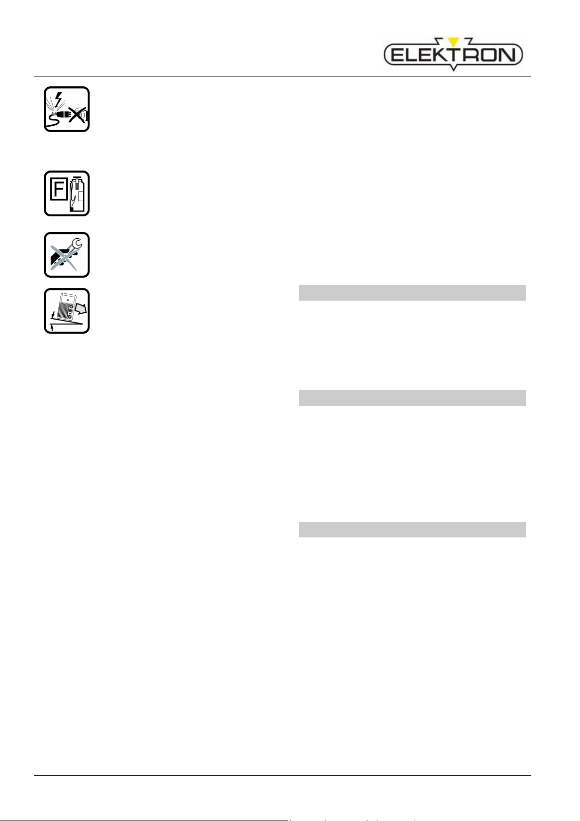
If the mains able is damaged or
severed in use, do not tou h the
able but unplug the mains plug
immediately. Never use a
ma hine if the mains able is
damaged.
Keep a fire extinguisher near the
welding area.
Che k the welding area for fire af-
ter welding (see UVV
1
)).
Never try to disassemble the pres-
sure redu er. Repla e the defe -
tive one.
The ma hine must be transported
or set up only on firm, level
surfa es. The maximum
admissible angle of in lination for
setting up or transporting is 10°.
Servi e and repair work may only be arried
out by a trained ele tri ian.
Ensure that the ground able has good and
dire t onta t near the welding lo ation. Do
not allow welding urrent to pass through
hains, ball bearings, steel ables or
grounding equipment; this may melt them.
Se ure yourself and the welding ma hine
when working in elevated or in lined areas.
The ma hine may only be onne ted to a
properly grounded mains supply. (Three-
phase four-wire system with grounded
neutral ondu tor or single phase-three-wire
system with grounded neutral ondu tor)
so ket and extension able must have a
fun tional prote tive ondu tor.
Wear orre t prote tive lothing, leather
gloves and leather apron.
Prote t the welding area with urtains or
mobile s reens.
Do not use this ma hine to thaw frozen
water pipes or ables.
In losed ontainers, under ramped on-
ditions, and in high ele tri al risk areas, only
use ma hines with the S sign.
Swit h off the ma hine during breaks and
lose the valve of the gas ylinder.
Se ure the gas ylinder with a hain to
prevent it falling over.
Dis onne t the mains plug from the mains
before hanging the pla e of installation or
making repairs to the ma hine.
Please heed the safety regulations whi h apply
to your ountry.
Subje t to hange.
4 General regulation of use
This unit is for welding of steel, aluminium and
their alloys as well as for brazing with CuSi
wires for ommer ial as well as for industrial
use.
5 Unit rotection
This ma hine is prote ted ele troni ally
against overloading. Do not use fuses of higher
amperage than printed on the identifi ation
plate.
Close the side over before starting any
welding work.
6 Noise emission
The noise level of the unit is less than
70 dB(A), measured under standard load in a -
ordan e with EN 60974-1 in the maximum
working point.

MULTIMIG 200
Electromagnetic com atibility (EMC)
7
7 Ambient conditions
Tem erature range of ambient air:
In operation:
-10 °C … +40 °C (+14 °F … +104 °F)
Transport and storage:
-25 °C … +55 °C (-13 °F … +131 °F)
Relative humidity:
up to 50 % at 40 °C (104 °F)
up to 90 % at 20 °C (68 °F)
-25 °C … +55 °C (-13 °F … +131 °F)
Opera
tion, storage and transport
may only be arries out within the
ranges indi ated! Use outside of
this range is onsidered not used
with its intended purpose. The
manufa turer is not liable for dam-
ages ause by misuse.
Ambient air must be free of dust, a ids, or-
rosive gases or other damaging substan es!
8 UVV ins ection
Operators of ommer ially-operated welding
systems are obliged to have safety inspe tions
of the equipment arried out regularly in
a ordan e with VDE 0544-4. ELEKTRON
re ommends inspe tion intervals of 12 months.
A safety inspe tion must also be arried out
after alterations or repair of the system.
Improper UVV inspe tions an
destroy the system.
9 Electromagnetic com atibility
(EMC)
This produ t is manufa tured in onforman e
with the urrent EMC standard. Please note
the following:
The ma hine is intended for welding in both
ommer ial and industrial appli ations
(CISPR 11 lass A). Use in other
surroundings (for example in residential
areas) may disturb other ele troni devi es.
Ele tromagneti problems during start-up
an arise in:
• Mains ables, ontrol ables, signal and
tele ommuni ation lines near the welding or
utting area
• TVs / radios
• Computers and other ontrol equipment
• Prote tion equipment su h as alarm
systems
• Pa emakers and hearing aids
• Equipment for measurement and alibration
• Equipment with too little prote tion against
disturban es
If other equipment is disturbed it may be
ne essary to provide additional shielding.
The affe ted area an be bigger than your
premises/property. This depends on the
building, et .
Please use the ma hine in omplian e with the
manufa turer's instru tions. The ma hine
operator is responsible for installation and use
of the ma hine. Furthermore, the owner is
responsible for eliminating the disturban es
aused by ele tromagneti fields.

MULTIMIG 200
Setu and trans ort
8
10 Set-u and trans ort
Danger of injury due to the de-
vice falling over and crashing!
When transporting using me hani-
al lifting equipment (e.g. rane,
et .), only the hoisting points shown
here may be used. Use suitable
load- arrying equipment.
Ea h lifting point must be loaded
separately. Do NOT,
for example
put one load strap through both
handles, as this ould lead them to
be pulled together and ause
breakage!
Do not use a fork-lift tru k or simi
lar
devi e to lift the ma hine by its
housing.
Remove the gas ylinder from the
welding ma hine before transpor-
tation.
The ma hine must be transported
or set up only on firm, level sur-
fa es. The maximum admissible
angle of in lination for
setting up or
transporting is 10°.
Fig. 2: Lifting point for 4-point hoisting

MULTIMIG 200
Brief o erating instructions
9
11 Brief o erating instructions
A detailed des ription an be found
in hapter. „Before start-
up“ Page
10 and hapter. „Start-up“ Page 14.
Pla e the inert gas ylinder on the unit and
se ure it with the hain 1.
Remove the s rew ap from the inert gas
ylinder and open the valve 32 briefly (blow-
out).
Conne t the pressure redu er 13 to the inert
gas ylinder.
Conne t the insert gas hose 5 from the unit
to the pressure redu er and open the
ylinder valve.
Insert the mains plug in the so ket.
Conne t welding return able to onne tor
10 and the lamp to the workpie e.
Insert wire feed rollers 25 into wire feed unit
in a ordan e with the type of welding wire
sele ted, set onta t pressure to 2.
Conne t the tor h to entral onne tor 11
and insert the relevant onta t tip to se-
le ted welding wire.
Insert welding wire.
Keep tor h swit h pressed and set main
swit h 9 ON. Magneti valve will be a -
tivated!
Adjust gas quantity at pressure redu er.
(Rule: wire diameter x 10 = gas quantity).
Hold down the wire feed swit h 29 until the
welding wire proje ts from the tor h ne k to
the gas nozzle by approx. 20 mm.
Mode key 47 for sele tion of 2-stroke mode.
Key hara teristi s 50 and operation knob
52 for adjusting the sele ted hara teristi
line (material-gas-wire- ombination).
Turn knob 45 to set material thi kness of
the weldable material.
Tor h swit h pressed and held = welding.
Release the tor h swit h = welding pro ess
ompleted.
MULTIMIG 200
Before start-u
10
12 Before start-u
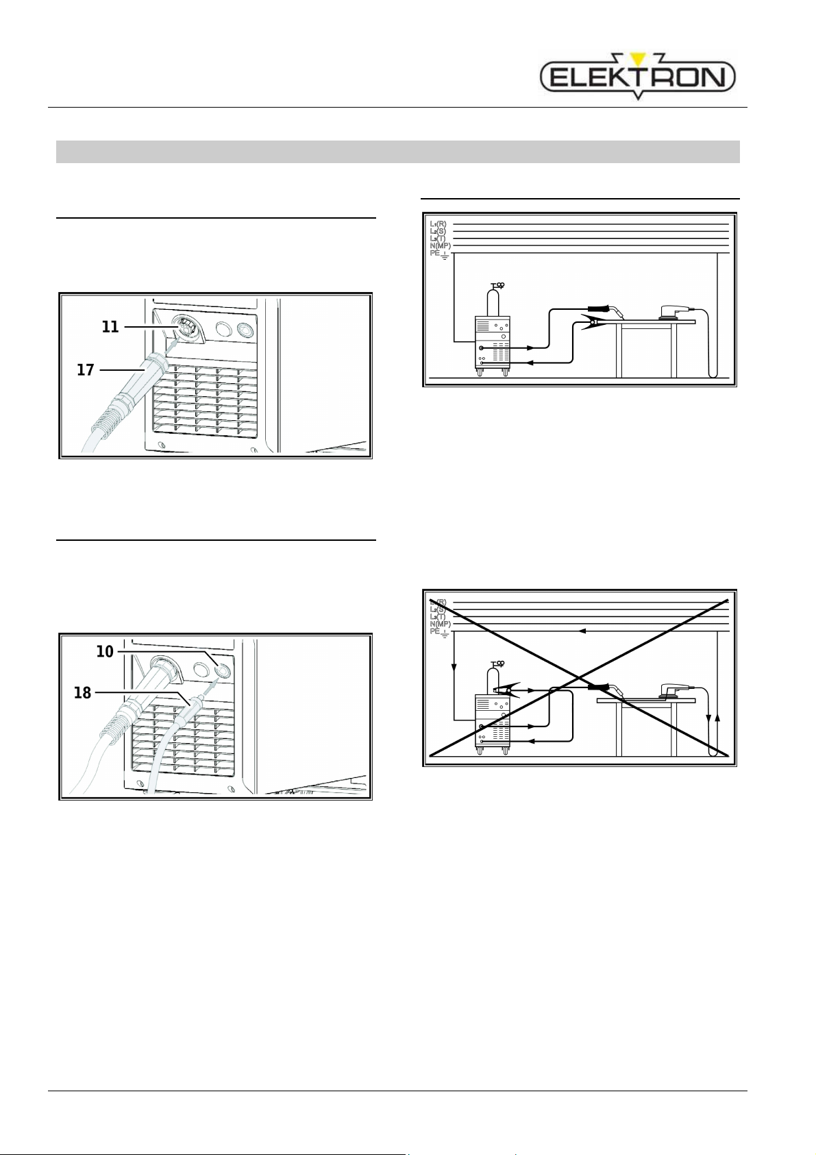
12.1 Connecting the torch
Conne t the entral onne tor 17 of the
tor h to the entral so ket 11.
Fig. 3: Connecting the torch
12.2 Connecting the ground cable
Conne t welding return able 18 to on-
ne tor 10 and se ure it by turning it lo k-
wise.
Fig. 4: Connecting the ground cable
12.3 Fastening the ground clam
Fig. 5: Correct
Atta h the ground lamp immediately be-
side the welding point so that the welding
urrent will not try to find its own return path
through ma hine parts, ball bearings or
ele tri ir uits.
Conne t the ground lamp firmly to the
welding ben h or the workpie e.
Fig. : Incorrect
Do not pla e the ground lamp on the
welding ma hine or the gas ylinder; oth-
erwise the welding urrent will be arried via
the prote tive ondu tors and it will destroy
these.
MULTIMIG 200
Before start-u
11
12.4 Insert the welding wire s ool
Danger to life and limb and fire
hazard due to glowing welding
wire or arts!
A protruding pie e of wire out of the
wire s
pool an ause short ir uits
to the side panel or bottom of the
unit.
When inserting the welding wire
spool, please pay attention to the
orre t winding and make sure that
there are no protruding pie es of
wire.
Set the wire brake in su h a way
that the wire spool doesn’t on
tinue
running when releasing the tor h
key.
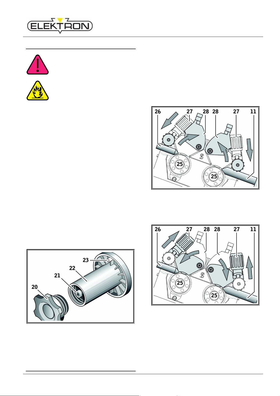
Open side panel and turn the retaining nut
20 off from the wire spool holder 22.
Pla e the welding wire reel on the de oiler
mandrel and ensure that the arrier mandrel
23 lo ks in position.
For small welding wire reels, use an adaptor
(order number: 420 922).
Set the wire brake 21 so that, when the
tor h swit h is released, the welding wire
spool just does not run on.
Fig. 7: Decoiler mandrel
12.5 Thread the wire electrode in
Uns rew the onta t tip of the tor h.
Open side panel.
The diameter of the wire ele trode must
agree with the legible embossed figure on
the wire feed rollers 25.
Swing the tilt levers 27 to the side and
thread the wire ele trode through the inlet
nozzle 26 and entral so ket 11.
Fig. 8: open 4-roll wire feed
Swing the lever ba k 28 and se ure in po-
sition with the tilt levers 27.
Fig. 9: close 4-roll feed
Turn on the ma hine at mains swit h 9.
MULTIMIG 200
Before start-u
12
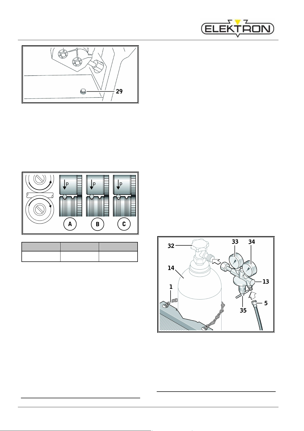
Fig. 10: Wire feed button
Press wire feed button 29.
Adjust the onta t pressure using the reg-
ulation s rews 27 so that wire feed rollers
25 just slip when the welding wire spool is
stopped. The wire must not be jammed or
deformed.
A B C
Corre t Conta t pressure
too high
Wrong wire feed
roller
Fig. 11: Wire feed rollers
Note for wire feed unit with 4 rollers:
Adjust the onta t pressure of the wire feed
rollers 25 on the side of the inlet nozzle 26
to be less than on the side of the entral
so ket 11 in order to keep the wire
ele trode under tension in the wire feed
unit.
Push the wire feed button 29 until the wire
protrudes from the tor h ne k by about
20 mm.
S rew the onta t tip mat hing the wire
thi kness into the tor h and ut off the
protruding end of the wire.
12.6 Connecting the inert gas cylinder
Set the insert gas ylinder 14 down on the
arrier plate and se ure it with the hain 1.
Briefly open the gas ylinder valve 32
several times in order to blow out any dirt
parti les present.
Conne t the pressure redu er 13 to the inert
gas ylinder 14.
S rew the inert gas hose 5 to the pressure
redu er.
Open valve 32 of shielding gas bottle 14.
Turn the ma hine off at main swit h 9.
Press tor h key and keep it pressed.
Turn on the ma hine at mains swit h 9.
Solenoid valve will be swit hed on for 10
se onds.
Set the gas quantity using adjusting s rew
35 of the pressure redu er 13. The gas
quantity will be displayed on the flowmeter
34.
Rule of thumb:
Gas volume = wire diameter x 10 l/min.
The ylinder ontent is indi ated on the
ontent manometer 33.
Fig. 12: Connecting the inert gas cylinder
12.7 Changing the wire electrode
MULTIMIG 200
Before start-u
13
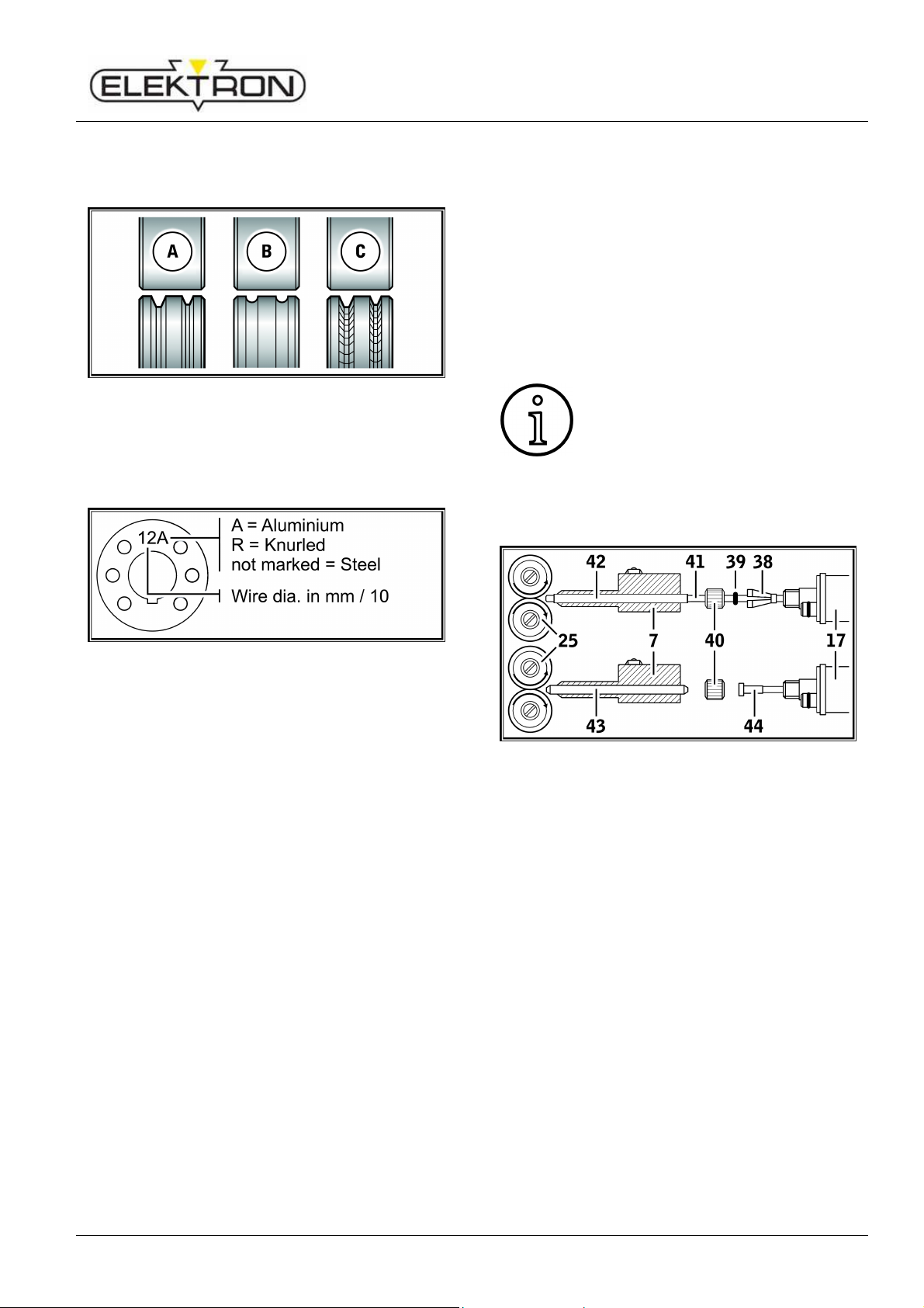
Change the wire feed rollers. Sele t the
most suitable rollers for the appli ation.
Fig. 13: Wire feed rollers
A Steel feed roller
B Aluminium feed roller
C Knurled feed roller (for flux- ored wire)
Fig. 14: Marking of wire feed rollers
Repla e the steel tor h with an appropriate
tor h, or hange the wire feed spiral.
Wire feed s iral: (for steel or flux-cored
wire)
Remove the existing wire feed spiral or
plasti ore and insert the new wire feed
spiral. (Refer to the operating manual for the
tor h)
Insert the guide tube 85 into the entral
onne tion.
Plastic core: (for aluminium, stainless steel
or CuSi wire)
Remove the existing wire feed spiral or
plasti ore and insert the new plasti ore.
(Refer to the operating manual for the tor h)
Remove the guide tube 85 from the entral
onne tion.
Shorten the protruding plasti ore so that it
is tight up against the wire feed roller, and
slide the appropriately shortened support
tube over the protruding plasti ore for
stabilisation.
All:
Tighten the tor h and thread the wire ele -
trode in.
The order numbers of the repla e-
ment parts depend upon the type of
tor h used and the diameter of the
wire, and an be obtained from
the
tor h spares lists.
Fig. 15: Wire feed
7 Central so ket
17 Central onne tion (tor h)
25 Wire feed roller
38 Retaining nipple (= lamp) of the plasti
liner for 4.0 mm and 4.7 mm outside
diameter
39 O-ring
40 Union nut
41 Plasti liner
42 Support tube for plasti ores with 4 mm
OD Support tube not required with OD of
4.7 mm.
43 Guide tube
44 Wire feed spiral

MULTIMIG 200
Start-u
14
13 Start-u
13.1 Control console MULTIMIG 200
Fig. 1 : Control console MULTIMIG 200
Fig. 17: Graphic display

MULTIMIG 200
Start-u
15
9 Main swit h for turning the welding
ma hine ON and OFF.
45 Turning knob for setting material
thi kness/welding voltage/welding step.
46 Key button se ondary parameter to
a ess the se ondary parameter menu.
When within this menu this key serves to
end it.
47 Trigger Mode to sele t 2-stroke, 4-stroke,
spot welding or interval mode.
48 Key button menu to a ess the main
menu. Pressing this key will move one
level ba k.
49 Graphi display displays all information in
lear text.
50 Key Tiptroni / hara teristi s dire t a ess
to the Tiptroni menu alt. hara teristi s
menu (if Tiptroni is swit hed off).
51 Key Se ondary parameter a ess the
se ondary parameter dire tly. Within the
menu press this key to end menu.
52 Operation knob Menu Turning knob wire
feed serves to:
• sele t menu (turn)
• onfirm menu option (press)
• setting wire feed
• setting se ondary parameter
55 Display mode displays the sele ted mode
by symbol.
56 Display hara teristi s displays the set
hara teristi line.
57 Display Tiptroni -Job if the job no. is
followed by an asterisk (*) on the display,
a min. parameter of a saved job has been
hanged.
58 Display wire feed orre tion displays the
wire feed as orre tion value differing from
the hara teristi line in %.
59 Display wire feed displays the a tual wire
feed speed in m/min.
60 Display welding step displays the sele ted
welding step.
61 Display material thi kness displays the
sele ted material thi kness of the
workpie e in mm.
62 Display welding voltage displays the
sele ted welding voltage in Volt.
13.2 Start-u
Sele t with mode key 47 the 2-stroke mode.
Press key hara teristi s 50 to enter menu
hara teristi s.
Set mat hing hara teristi line (material-
gas-wire ombination) by turning operation
knob 52.
Confirm the hara teristi line by pressing
operation knob 52.
Press operation knob 52 again to end menu
and return to standard display.
Set the required material thi kness alt.
welding step by using turning knob 45.
The ma hine is ready for welding.
Use operation knob 52 to orre t the wire
feed if needed.

MULTIMIG 200
Start-u
16
13.3 Current / voltage dis lay
The a tual values of welding voltage and
welding urrent are displayed during and after
welding (hold fun tion).
These values an be displayed individually or
together on the graphi display.
Possible display:
Welding voltage and welding urrent
Welding voltage
Welding urrent
Fig. 18: Display mode
Change of dis lay modern
Press menu key 48.
Sele t menu option „Display mode“ by
pressing operation knob 52.
Confirm menu option „Display mode“ by
pressing operation knob 52.
Set the desired display mode by turning
operation knob 52.
Confirm the desired display by pressing
operation knob 52.
For about 2 se onds a preview of the dis-
play will be shown if the display mode has
been hanged.
13.4 Torch with remote control
Fig. 19: Torch PowerMaster
65
Tor h display displays the a tual welding
step or wire feed speed in Tiptroni mode.
The urrent job will be displayed.
66 Tor h ro ker swit h Change welding step
and wire feed speed. Between a tive jobs
an swit hed over whilst being in Tiptroni
mode.
67 Tor h key „Mode“ By pressing (for at least
2 se onds) hangeover between Tiptroni
and regular mode will take pla e. A qui k
press in regular mode hange between
wire feed, welding step and material
thi kness (at sele ted hara teristi s).
13.5 Deactivate o eration mode
The operation mode spot welding and interval
an be dea tivated in the menu and will no
longer be a essable with mode key 47.
Press key menu 48.
Set menu to „options“ by turning operation
knob 52.
Confirm menu „options“ by pressing op-
eration knob 52.
Set the menu option „interval welding“ or
„spot welding“ by turning operation knob 52
for dea tivation.
Confirm the menu option by pressing opera-
tion knob 52.
Sele t and onfirm the menu option „off“ by
using operation knob 52.
MULTIMIG 200
Start-u
17
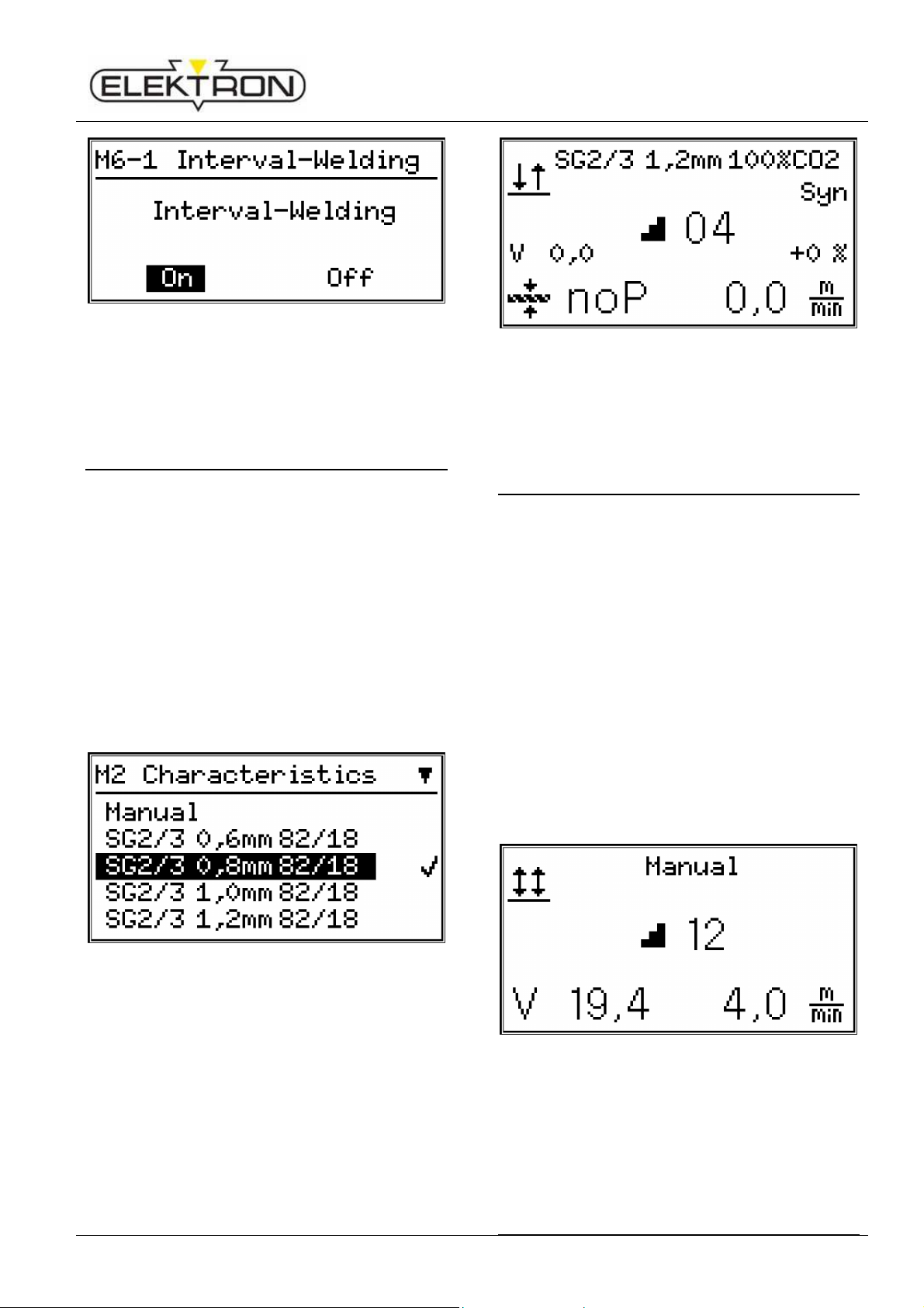
Fig. 20: Interval-welding deactivated
Press key 46, 50 or 51 to end menu and
return to standard display.
13.6 Characteristic line
Select characteristic line
Press key menu 48.
Set menu option „ hara teristi line“ by
turning operation knob 52.
Confirm menu option „ hara teristi line“ by
pressing operation knob 52.
Set required hara teristi line by turning
operation knob 52.
Confirm hara teristi line by pressing op-
eration knob 52.
Fig. 21: Characteristics
Press key 46, 50 or 51 to exit menu and
return to standard display.
If the graphi display shows „noP“ (no pro-
gram) for material thi kness, the set welding
step is inappli able for the sele ted
hara teristi line.
Fig. 22: „noP“ (no program)
Sele t a suitable welding step with turning
knob 45.
13.7 Mode Manual
Manual welding mode allows welding inde-
pendent of hara teristi lines.
Press key menu 48.
Sele t menu option „ hara teristi s“ by
turning operation knob 52.
Confirm menu option „ hara teristi s“ by
pressing operation knob 52.
Sele t menu option „manual“ by turning
operation knob 52.
Confirm menu option „manual“ by pressing
operation knob 52.
Press key 46, 50 or 51 to exit menu and
return to standard display.
Fig. 23: Manual mode
13.8 Secondary arameters
MULTIMIG 200
Start-u
18
Press key se ondary parameter 46 or 51 to
open the se ondary parameter menu.
Sele t the required se ondary parameter by
turning operation knob 52.
Confirm set se ondary parameter by
pressing operation knob 52.
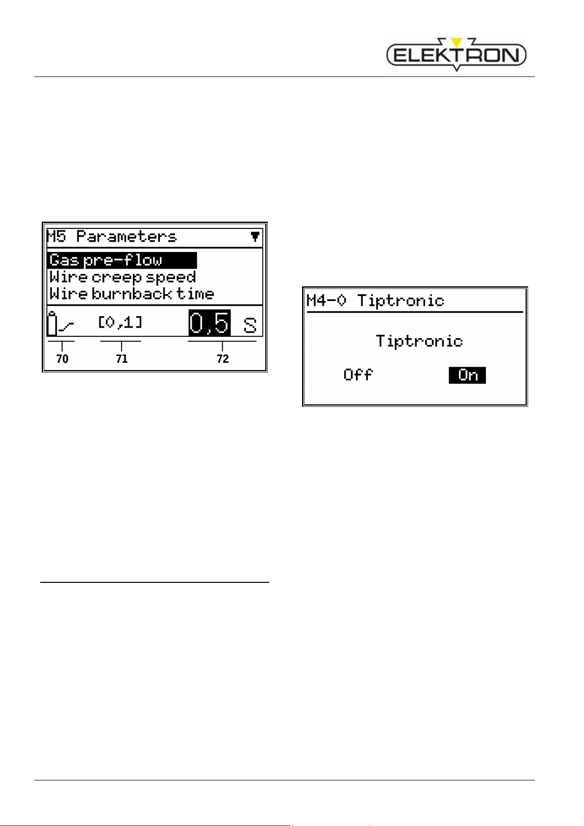
Set parameter value 72 as required by
turning operation knob 52.
Fig. 24: Secondary parameters
70 Symbol se ondary parameter
71 Fa tory setting
72 Parameter value
Confirm parameter value 72 by pressing
operation knob 52.
Press key 46, 50 or 51 to exit menu and
return to standard display.
13.9 Ti tronic
The Tiptroni fun tion provides 10 separate
jobs. All settings and adjustments made on the
ontrol panel are stored in ea h job.
The Tiptroni fun tion also gives the user
ertain advantages, e.g. frequently re urring
welding jobs an be assigned to spe ifi job
numbers, or different welders an save their
individual settings in „their“ job.
Fa tory setting for Tiptroni fun tion is de-
a tivated.
Activate Ti tronic
Press key menu 48.
Sele t menu option „Tiptroni “ by turning
operation knob 52.
Confirm menu option „Tiptroni “ by pressing
operation knob 52.
Set menu option „Tiptroni on/off“ by turning
operation knob 52.
Confirm menu option „Tiptroni on/off“ by
pressing operation 52.
Set and onfirm option „on“ with operation
knob 52.
Fig. 25: activate Tiptronic
Press key 46, 50 or 51 to exit menu and
return to standard display.
Save job
Press key Tiptroni 50.
Set menu option „Job save“ by turning op-
eration knob 52.
Confirm menu option „Job save“ by pressing
operation knob 52.
Sele t the required saving position
(J00 … J09) by turning operation knob 52.
Confirm the job by pressing operation knob
52.
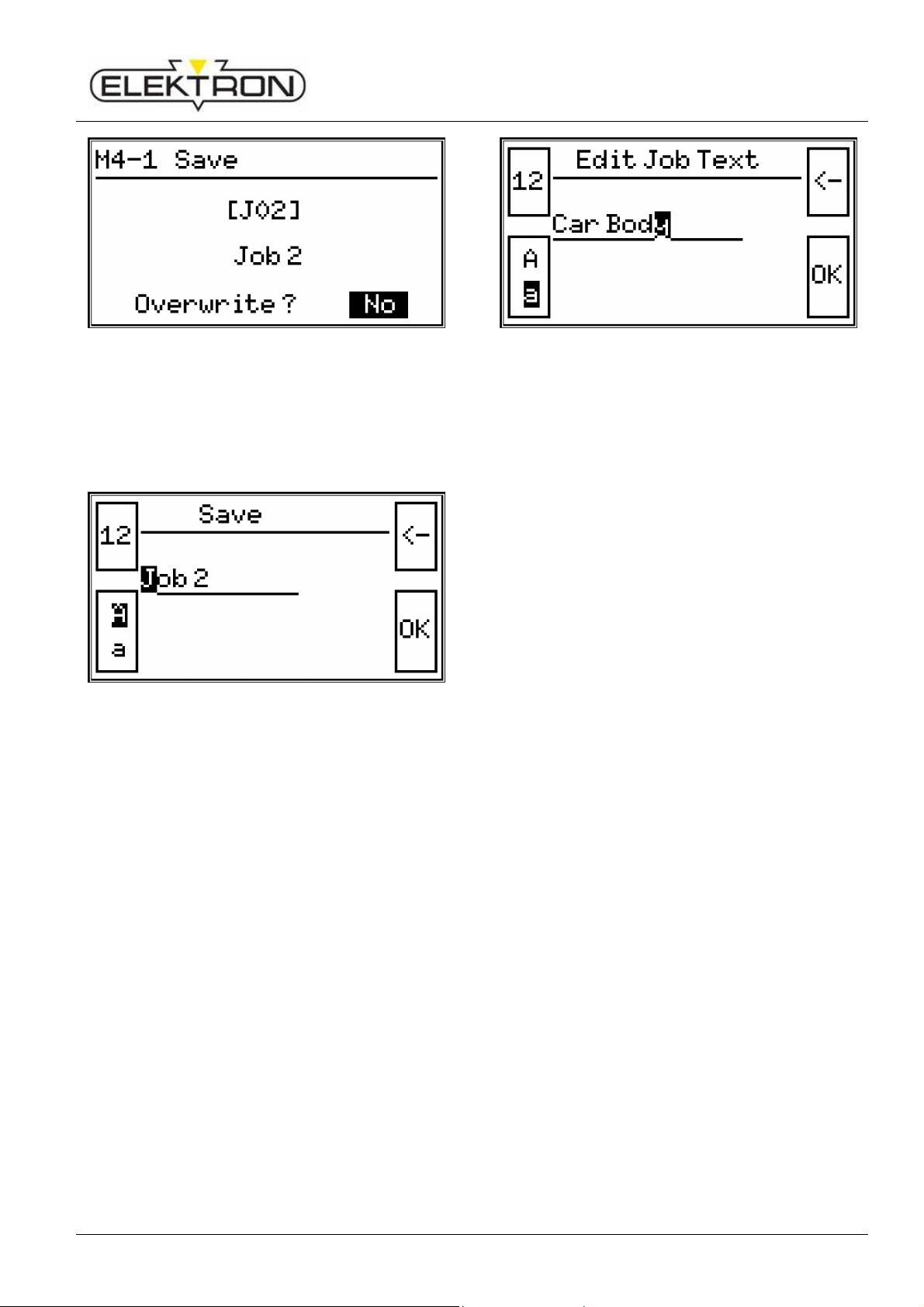
If the job to be saved is already existent / al-
lo ated; a safety question before overwriting
appears.
MULTIMIG 200
Start-u
19
Fig. 2 : safety question
Sele t „YES“ for overwriting the job by
turning operation knob 52.
Confirm „YES“ by pressing operation knob
52.
Fig. 27: Save job
If required the job name an be hanged.
(see „edit job ext).
Save the job by pressing key 51.
Press key 46, 50 or 51 to exit menu and
return to standard display.
Edit Job-text
Press key Tiptroni 50.
Set menu option „edit job text“ by turning
operation knob 52.
Confirm menu option „edit job text“ by
pressing operation knob 52.
Sele t the job no. where text must be edited
by turning operation knob 52.
Confirm the job no. by pressing operation
knob 52.
Fig. 28: edit job text
Press key mode 47 to edit numbers.
Press key se ondary parameter 46 to edit
letters.
Repress key se ondary parameter to
hange between apital and small letters.
Set the required number or letter by turning
operation knob 52.
Confirm number or letter by pressing op-
eration knob 52.
Repeat above pro edure for ea h hara ter.
Use key Tiptroni 50 to go ba k stepwise in
order to orre t a hara ter.
Press key se ondary parameter 51 to fi-
nalize the saving pro ess.
Press key 46, 50 or 51 to exit menu and
return to standard display.
Select job
Press key Tiptroni 50.
Set menu option „sele t job“ by turning
operation knob 52.
Confirm menu option „sele t job“ by press-
ing operation knob 52.
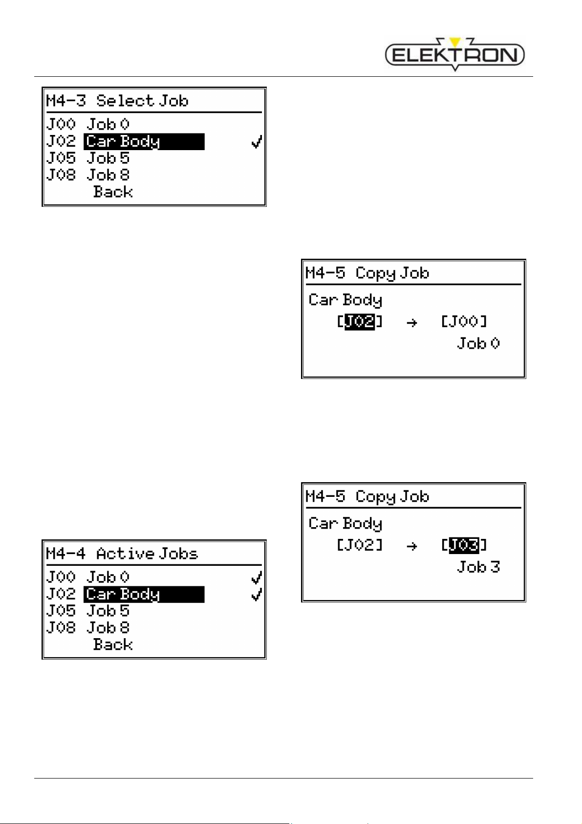
A listing of all existing jobs will be displayed
in the menu. The urrently sele ted job is
marked with a ti k (√) on the right side.
MULTIMIG 200
Start-u
20
Fig. 29: select job
Set the required job by turning operation
knob 52.
Confirm the job by pressing operation knob
52.
Active job summary
Tiptroni -Jobs an be set either a tive or in-
a tive.
When PowerMaster tor h is onne ted and
Tiptroni fun tion is a tive, use ro ker swit h to
swit h between a tive jobs.
Press key Tiptroni 50.
Sele t menu option „A tive Jobs“ by turning
operation knob 52.
Confirm menu option „A tive Jobs“ by
pressing operation knob 52.
A listing of all existing jobs will be displayed
in the menu. All a tive jobs are marked with
a ti k (√) on the right side.
Fig. 30: Active job summary
Sele t the job to be a tivated or dea tivated
by using operation knob turning knob 52.
A tivate or dea tivate the job by pressing
operation knob 52.
Press key 46, 50 or 51 to exit menu and
return to standard display.
Co ying a job
Press key Tiptroni 50.
Sele t menu option „ opy job“ by turning
operation knob 52.
Confirm menu option „ opy job“ by pressing
operation knob 52.
Sele t the job to be opied by turning op-
eration knob 52.
Fig. 31: Copy job: source
Confirm the job by pressing operation knob
52.
Sele t the job to be overwritten by turning
operation knob 52.
Fig. 32: Copy job: target
Confirm the job by pressing operation knob
52.
Safety question „ opy job?“ appears.
Sele t „YES“ to opy by turning operation
knob.
Table of contents
Other Elektron Welding System manuals

Elektron
Elektron MULTIMIG 400puls User manual

Elektron
Elektron MULTISPOT M20 User manual

Elektron
Elektron MULTISPOT M80 User manual

Elektron
Elektron MULTISPOT MI-90 T User manual

Elektron
Elektron MULTISPOT MI-100-3 User manual

Elektron
Elektron MULTISPOT MI-100control User manual

Elektron
Elektron KERCOMET 170 User manual

Elektron
Elektron MULTISPOT MI-100 User manual


