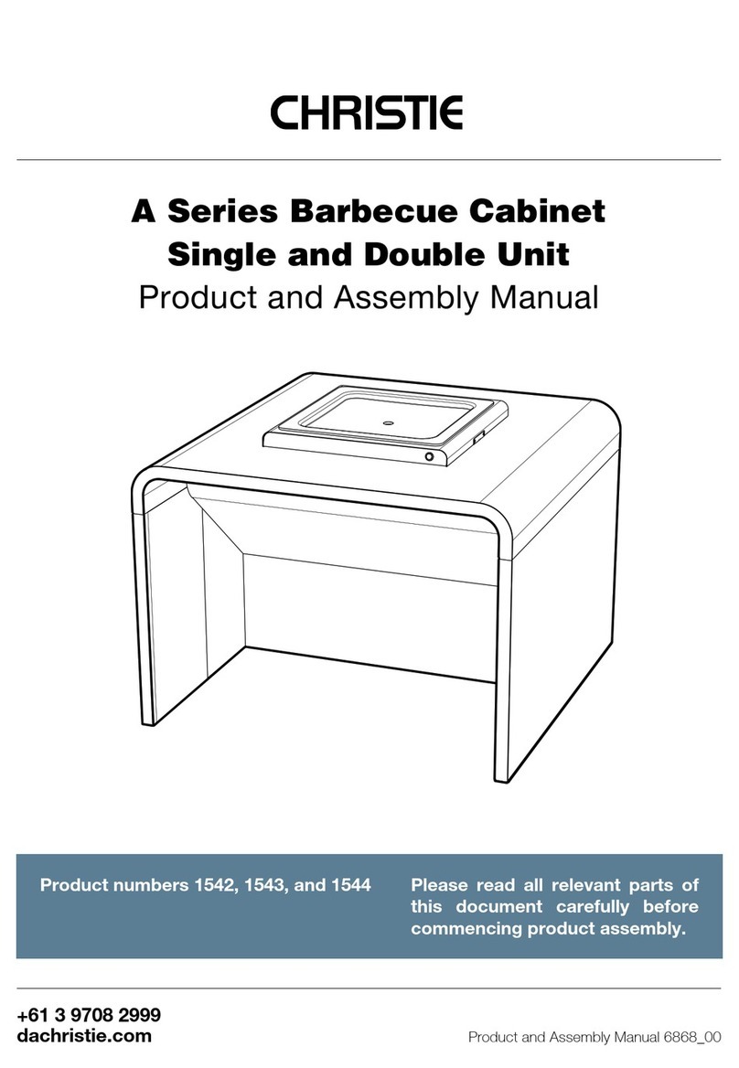
Christie ICON 1560 User manual

ICON Series Cabinet
Standard and Large
Product and Assembly Manual
dachristie.com
+61 3 9708 2999
Product number 1560, 1561, 1562, 1563,
1564, 1566, 1567, 1568, 1569, 1570, 1571,
1572, 1573, 1574, 1575
Please read all relevant parts
of this manual carefully before
commencing product assembly.
ICON Cabinet Product and Assembly Manual 6885_00

ICON Series Cabinet Standard and Large
2| Table of contents
1 GENERAL INFORMATION 3
1.1 Safety instructions 4
1.2 How to read this manual 4
1.3 Manufacturer liability 5
1.4 Conditions of use 5
1.5 Description 5
1.6 Disposal 5
2 SPECIFICATIONS 6
2.1 Siting Guidelines 7
2.2 Tools required 7
2.3 Specifications 7
3 STANDARD CABINET DIMENSIONS AND INSTALLATION 8
3.1 Standard Cabinet - dimensions | Figure 1 9
3.2 Standard Cabinet - services and footings | Figure 2, 3 10
3.3 Standard Cabinet - boxed contents and parts identification | Figure 4 12
3.4 Assembly and installation | Figure 5, 6, 7, 8, 9, 10,11, 12, 13, 14, 15, 16, 17, 18 13
4 LARGE CABINET DIMENSIONS AND INSTALLATION 24
4.1 Large Cabinet - dimensions | Figure 19 25
4.2 Large Cabinet - services and footings | Figure 20, 21 26
4.3 Large Cabinet - boxed contents and parts identification | Figure 22 28
4.4 Assembly and installation | Figure 23,24, 25, 26, 27, 28, 29, 30, 31, 32, 33, 34, 35, 36 29
5 OPTIONS AND ACCESSORIES 40
6 CLEANING AND MAINTENANCE 42
6.1 Safety considerations 43
6.2 Environmental considerations 43
6.3 Cleaning and general maintenance 43
6.4 Cleaning waste containers | Figure 37 44
7 WARRANTY 46

ICON Cabinet Product and Assembly Manual 6885_00
3General information |
1.

ICON Series Cabinet Standard and Large
4| General information
1.1 Safety instructions
| General information
Risk of personal injury
• Altering the product or variation from the
original specification may result in injury
and void the Product Warranty
• Use personal protection equipment
including gloves, safety glasses, and ear
protection during installation
• Do not sit or stand on the barbecue cabinet
at any time
• For safety reasons, do not store (LPG) gas
bottles inside the cabinet at any time
Risk of damage to the product
• During assembly, take suitable
precautions against scratching
surfaces and components
• Corrosive cleaning products may
damage the surfaces and coatings,
voiding any warranty claim. Use
only non-toxic, pH-neutral cleaning
products (with a pH between 6 and 9)
• Products intended for cleaning mild
steel may damage stainless steel
surfaces and must not be used
• Do not place heavy objects on the
benchtop
1.2 How to read this manual
Chapter headings and subheading are listed in the Table of Contents along with the
relevant page numbers.
Key words:
• “Must” and “must not” are mandatory instructions
• “Should’ and “should not” are advisory instructions
The following icon is used throughout the manual
Warning or Caution icons warn how to
prevent personal injury and product damage

ICON Cabinet Product and Assembly Manual 6885_00
5General information |General information |
1.3 Manufacturer’s liability
The manufacturer declines all liability for damage to persons or property caused by:
• The use of non-original spare parts
• Use of the product other than as intended
• Modifying or tampering with any part of the product
• Not observing the instructions contained in this Product and Assembly Manual
1.4 Conditions of use 1.5 Description
• The product must be assembled,
installed and maintained as per the
manufacturer’s instructions
• Christie cabinets are intended for use
with Christie cooktops only
• Christie Barbecues accepts no
responsibility for warranty repairs
made without prior authorisation
• This manual should be kept in its
entirety for the design life of the product
• The safety instructions in Section 1.1
form part of the Conditions of Use
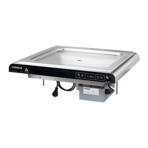
• The ICON Series is a robust, durable
barbecue cabinet, designed to safely
house Christie barbecue cooktops and
waste containers
• Cabinets are shipped flat-packed
to reduce transportation costs and
facilitate site access. They are ready for
assembly by following the step-by-step
instructions in this manual
• Stainless-steel construction provides
ultimate vandal resistance and ease of
cleaning and maintenance
1.6 Disposal
• The product does not contain substances considered hazardous to health or the
environment, according to current Australian and European directives
• When disposing of the product, please remove and deliver the metal components to an
appropriate recycling facility
• Christie appliances are packaged in non-polluting and recyclable materials. Please
recycle according to local regulations

ICON Series Cabinet Standard and Large
6
2.
SPECIFICATIONS
| Specifications

ICON Cabinet Product and Assembly Manual 6885_00
7Specifications |
• Barbecue facilities should be installed in plain view, where they can be monitored for
safe and appropriate use
• Ensure there are no climbing aids that will allow children access to the cooking surface
• Cabinet doors require a minimum 1000 mm clearance when opened
• Ensure there is at least 1200 mm clearance above barbecue cooking surfaces
• Due to the nature of this product, it requires clear access to all sides. The recommended
minimum slab size is 900 mm larger than the cabinet benchtop on all sides
• Recommended slab thickness is 100 mm
• When designing for access and mobility in Australia and New Zealand, please refer to the
Australian Standard, AS 1428 (Design for access and mobility)
Christie ICON Series barbecue cabinets are manufactured entirely from stainless steel for
ultimate durability and corrosion resistance.
ICON cabinets are available in #4 brushed stainless steel finish, or powder coated in an
extensive range of powder coating colours. The product is designed to allow for several
configurations and combinations of sinks and cooktops.
Note: All illustrations and instructions apply only to standard cabinets. Some assembly and
parts supplied for custom configurations may vary from what is specified in this manual.
2.1 Siting Guidelines
2.2 Tools required
2.3 Specifications
• 10 mm Spanner
• Masonry drill with 8 mm masonry drill bit
• Masonry anchors to suit 8 mm diameter
hole (a minimum of 4 anchors required
for all cabinets)
• Spanner to suit masonry anchors
Important: Do not use an impact driver.

ICON Series Cabinet Standard and Large
8
3.
ICON SERIES
STANDARD
CABINET
dimensions and installation
(For ICON Series Large Cabinet installation, see Section 4)
| Standard cabinet assembly and installation

ICON Cabinet Product and Assembly Manual 6885_00
9Standard cabinet assembly and installation |
Dimensions: 1250 mm wide x 1000 mm deep x 860 mm high
Weight: 70 kg (without cooktop)
Cooktop cut-out: 495 mm x 495 mm
3.1 Standard Cabinet - dimensions
FIG. 1 1250 mm
FRONT
940 mm
800 mm
REAR
362 mm 415 mm
538 mm
860 mm
SIDE
1000 mm
692 mm
465 mm

ICON Series Cabinet Standard and Large
10
3.2 Standard Cabinet - services and footings
Footings and underground services:
• Bring up underground services (electrical conduits, gas and water pipes and waste
outlets) in the highlighted areas only
• Position the gas or electric services relative to the preferred location and orientation of
the cooktop(s)
WARNING: All work on underground services must be carried out only
by suitably qualified trades people i.e. electricians or gas fitters.
FIG. 2
| Standard cabinet assembly and installation
940 mm
870 mm
570 mm
690 mm
370 mm
800 mm
120 mm
Services

ICON Cabinet Product and Assembly Manual 6885_00
11
3.2 Standard Cabinet - services and footings
Terminating the services:
Terminate services for standard cabinet configurations in the locations indicated below.
These locations will differ, depending on whether gas or electric cooktops are installed.
For Christie CC2 Gas Barbecue Cooktop:
• The gas inlet is on the right-hand side when facing the front of the cooktop
• The power supply cable is on the right-hand side when facing the cooktop
• Position the 10A electrical socket (GPO) at least 600 mm above ground (if required)
• Position the battery box on either side of the waste container (if required)
Christie Electric CC2 Barbecue Cooktop:
• The 1m electric cable with plug terminates into the left-hand side when facing the front
of the cooktop
• Position the 15A electrical socket (GPO) at least 600 mm above ground
FIG. 3
Standard cabinet assembly and installation |
Suggested
mounting locations

ICON Series Cabinet Standard and Large
12
Christie standard size ICON Cabinets are supplied with the following boxed contents:
1. (1) x Stainless steel benchtop
2. (2) x Side panels
3. (2) x In-fill panels
4. (1) x Rear panel
5. (1) x Foot panel
6. (1) x Knee panel
7. (1) x Door assembly
8. (1) x Lower door panel
9. (1) x Waste collection tray
10. (1) x Waste tray mount
11. (33) x 6 mm Bolts (not shown)
12. (10) x 6 mm Nuts (not shown)
13. (2) x Access door keys (not shown) supplied attached to the door
14. Installation and User Manual (not shown)
3.3 Standard Cabinet - boxed contents and parts identification
FIG. 4
| Standard cabinet assembly and installation
10
9
2
3
3
5
6
1
2
7
4
8

ICON Cabinet Product and Assembly Manual 6885_00
13Standard cabinet assembly and installation |
STEP 1
Open the carton and review the boxed contents section relevant to your product model. Check
that all listed parts are present. Contact Christie immediately if you notice any discrepancies.
Note: Leave the benchtop inside the carton until step 8
3.4 Assembly and installation
Wear suitable personal protective equipment (PPE) at all times.
Please read all relevant installation instructions before assembling
the cabinet.

ICON Series Cabinet Standard and Large
14
STEP 2
3.4 Assembly and installation
Assemble the cabinet in the final location. Ensure panels are placed in
their correct positions before fixing.
1. Locate and unpack the two side panels, foot panel, and rear panel.
2. Remove the in-fill panels from each side panel and set these aside.
3. Assemble the foot panel and side panels. Secure using (4) x M6 bolts. Ensure that the
foot panel ventilation slots are on the bottom.
4. Install the rear panel between the two side panels. Secure using (10) x M6 bolts.
Note: Brushed stainless steel cabinets will have a protective film on the outer surface.
Peel back the film from internal and adjoining surfaces before assembly.
| Standard cabinet assembly and installation
FIG. 5

ICON Cabinet Product and Assembly Manual 6885_00
15
3.4 Assembly and installation
Standard cabinet assembly and installation |
FIG. 6
FIG. 7

ICON Series Cabinet Standard and Large
16
3.4 Assembly and installation
STEP 3
1. Locate the door keys (provided in a bag with these installation instructions) and open the door.
2. Remove the door by releasing the spring-loaded latch pins. Set aside for reinstallation.
3. Remove the lower door panel by sliding the panel upward and then away from the rear
panel. Set aside for reinstallation.
Important: Retain the nylon door washer for reinstallation.
| Standard cabinet assembly and installation
FIG. 8
FIG. 9

ICON Cabinet Product and Assembly Manual 6885_00
17
3.4 Assembly and installation
Standard cabinet assembly and installation |
STEP 4
FIG. 10
The Cabinet must be square before marking and drilling fixing holes.
The internal distance between end panels must be 800 mm (refer FIG
02 in Section 3.2).
1. Place the cabinet in the final fixed position.
2. Tighten all fixings on the rear, side, and foot panels.
3. Mark out the fixing holes.
4. Move the cabinet to one side and drill the fixing holes with an 8 mm drill bit.
5. Move the cabinet back into the final fixing position and align the pre-drilled fixing
holes with the frame. Bolt down with suitable masonry anchors.
Important: It is critical to the operation of the appliance that the cabinet is stable and level.
Use packers to resolve minor levelling discrepancies or a bed of mortar for larger gaps.

ICON Series Cabinet Standard and Large
18
3.4 Assembly and installation
STEP 5
Reinstall the in-fill panels into the corresponding side panels.
FIG. 11
| Standard cabinet assembly and installation

ICON Cabinet Product and Assembly Manual 6885_00
19
3.4 Assembly and installation
Standard cabinet assembly and installation |
STEP 6
Install the knee panel. Secure using (19) x M6 bolts.
Important: Do not scratch external surfaces when lowering the knee panel.
Note: Brushed stainless steel finish panels will have a protective film. Remove the entire
film before installation.
FIG. 12

ICON Series Cabinet Standard and Large
20
3.4 Assembly and installation
FIG. 13
| Standard cabinet assembly and installation
STEP 7
WARNING: Services must only be connected by a suitably qualified
person, i.e. electrician or gas fitter.
If your installation has 240v Power outlets (GPO’s), install these now. Fix services to internal
mounting plates or a secure location. Do not fix to external surfaces (refer FIG 03 in Section
3.2). Complete the gas provisioning (if required).
STEP 8
1. Remove the benchtop from the carton and gently lower it onto the cabinet, ensuring
that the pins are inserted into the corresponding fixing holes.
2. Secure the benchtop using the (10) x 6 mm nuts.
This manual suits for next models
14
Table of contents
Other Christie Grill manuals