Christini AWD KTM User manual

Service Manual
Christini Technologies, Inc.
tech@christini.com
Version 2011-1.0
CHRISTINI AWD KTM
CHRISTINI AWD KTMCHRISTINI AWD KTM
CHRISTINI AWD KTM


Page 2
Warnings:
•
Do not adjust the choke while the bike is moving!

Page

Page 4
Table of Contents
Introduction; required tools
5
AWD detailed illustration 6
Routine maintenance schedule 7
AWD clutch test 8
AWD chain removal 9
AWD engagement adjustment 11
ront wheel removal 12
ront wheel service 14
ork removal and installation 21
Dropout service 23
ork spline bearing service 32
Triple clamp removal 39
Bottom triple clamp disassembly 41
Bottom taper bearing removal 48
Bottom triple clamp assembly 49
Top triple clamp disassembly 53
Top taper bearing removal 54
Top triple clamp assembly 55
Main drive shaft service 56
Headset bearing service 57
Gearbox removal 64
Gearbox/Transfer Case Service 67
AWD clutch Service 81
Troubleshooting 85
Warranty 86
AWD cable removal 65
Boot Replacement 37
Table of Contents

Page 5
•
Socket set, metric
•
Pliers set
•
all peen/ dead blow hammers
•
Soft tip metal punch (brass/aluminum)
•
Screw driver set
•
AWD clutch wrench (optional)
•
Open ended wrenches, metric
•
Allen key set, metric
•
Snap ring pliers, 45 or 90 degree
•
earing punch set
•
lind side bearing removal kit (Motion Pro 08-0292)
•
2 large adjustable wrenches
•
Torque wrench 0-75 ft-lbs
•
Split bearing puller
•
Small pick or awe
•
Safety wire pliers
•
Safety wire .032”
•
Grease gun (included with frame kit. Fill with Shell grease)
•
Shell Albida EP1 Lithium grease (do not substitute)
•
Spectro SPL grease of equivalent
•
lue Loctite #242
•
Red Loctite #262
•
Green Loctite #609
The Tools You Will Need for Maintenance
Required Tools

Page 6
AWD Detail Illustration

Page 7
Pre-ride check list:
•
Check secondary AWD chain tension.
•
Lube secondary AWD chain.
•
Check clutch setting with front wheel torque test (see next page).
•
Check front wheel rim lock nut torque.
As Needed
•
Replace bearings if excessive noise or friction develops.
•
Lubricate spline shafts through grease port with supplied grease
gun and Shell grease.
•
Replace worn or damaged seals and boots.
Routine Maintenance
AVOID:
AVOID:AVOID:
AVOID:
•
Pressure washing the dropouts, head tube area, side bar
and main gearbox.
Page 8
•
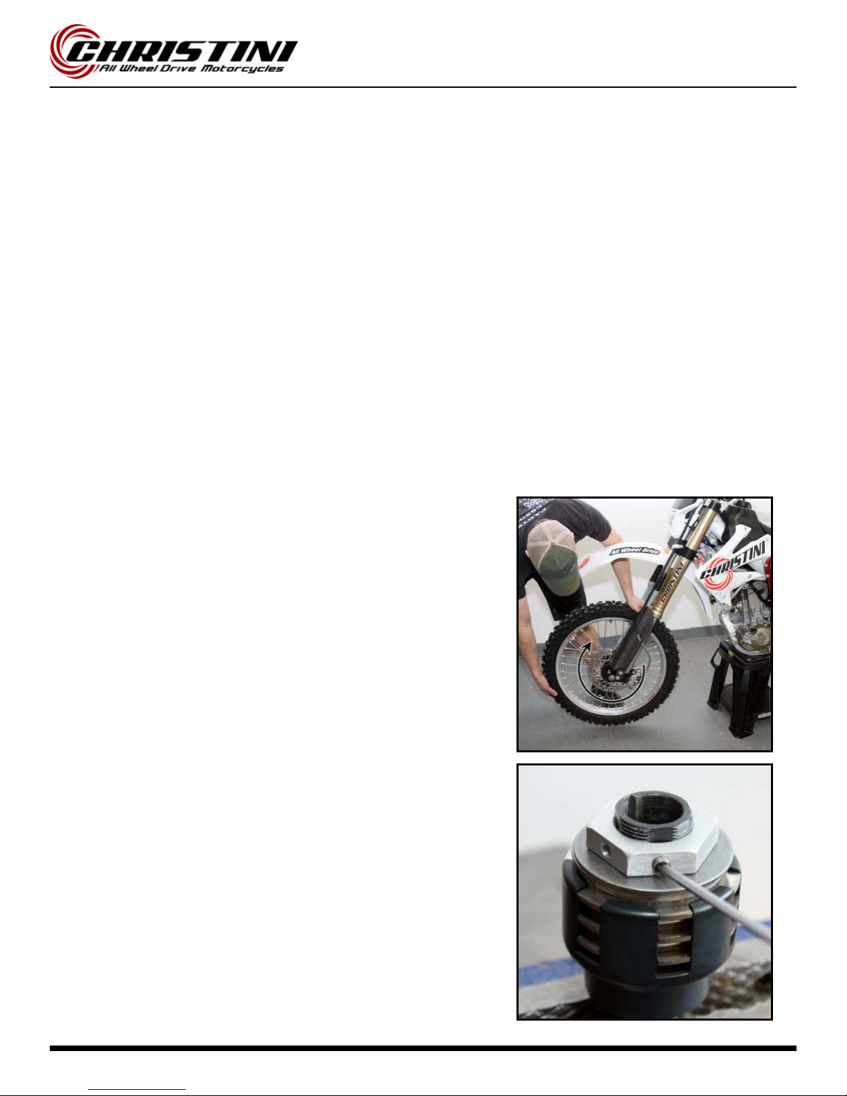
Place the bike on a stand and make sure that the front wheel is
not touching the ground.
•
Shift the bike into gear.
•
Turn the AWD switch to the on position and check to make sure
the AWD is engaged.
•
Grab the front wheel with two hands and try to spin it backwards.
The front wheel should spin backwards but require a large amount
of effort to do so. If the wheel will not break free, the clutch is set
too high. If the wheel turns backwards very easily, the clutch is set
too low.
•
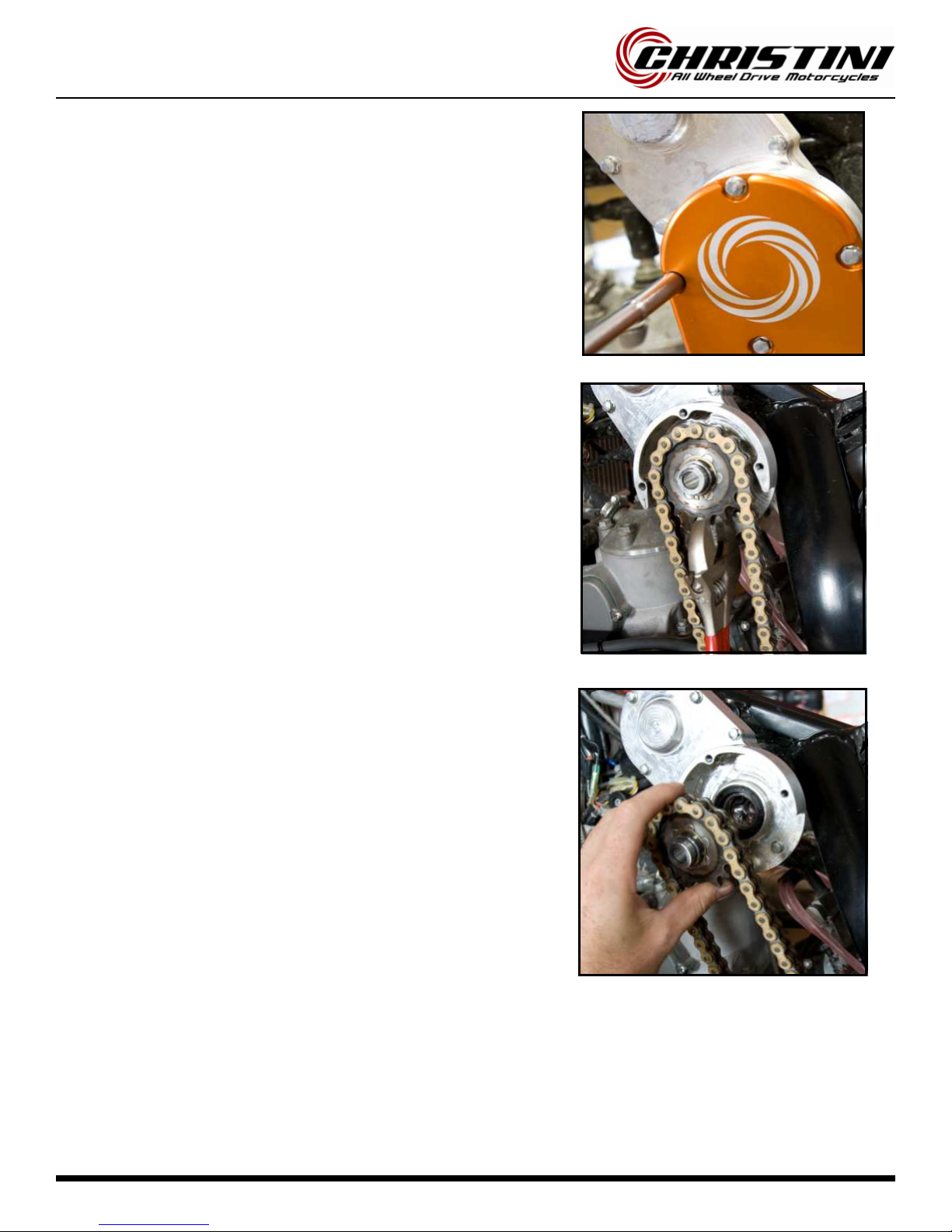
If the clutch needs to be adjusted, pull the gas tank off the bike.
Loosen the set screw on the clutch locknut and turn the locknut in
or out a 1/2 turn at a time until the front wheel moves backward
with the correct amount of force. Make sure the set screw is posi-
tioned over a flat in the clutch hub and tighten the set screw down
and reinstall the tank. (note: picture shows clutch off the bike for
clarity).
AWD Clutch Test
There are two ways to check that the clutch is set to the right torque. The first method is to take the clutch off the
bike and use the Christini AWD clutch tools and a torque wrench (see page 74). This is only recommended when the
clutch assembly is being rebuilt with new pads. The following test should be sufficient under most circumstances:
Page 9
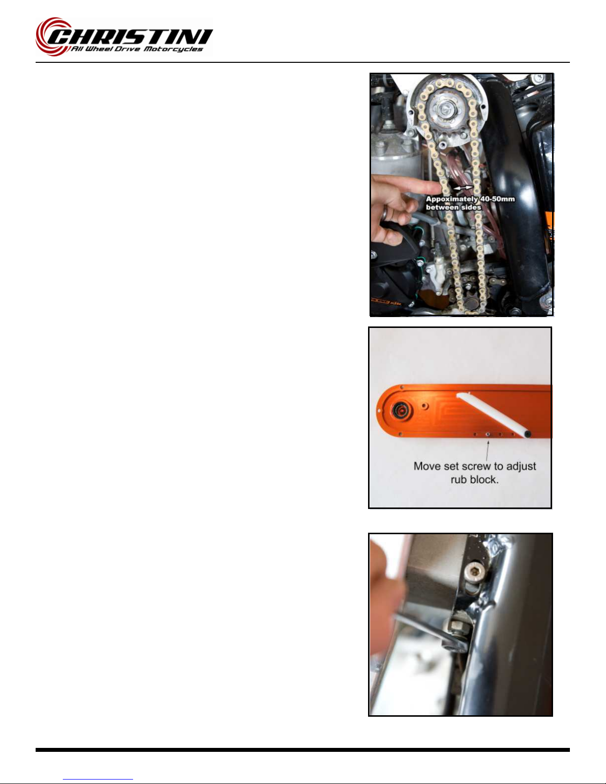
• Remove the 4 cover bolts with an 8mm socket or t-handle and pull
cover off of the frame.
• To remove the chain, pull the sprocket out with fingers or non-
marring pliers. Remove the chain from countershaft sprocket.
• Check the following:
1. Sidebar bearing and cover bearing should be smooth turn
ing.
2. Check engagement spline action by engaging and disen-
gaging switch on handle bars.
3. Sidebar seal and cover seal for wear.
4. Excessive wear on chain tension block.
Warning:
Warning:Warning:
Warning: Do not use an O-ring chain as there is not enough
clearance for one and it would rub the frame.
Cover and Chain Removal
Page 10
• Reinstall chain and top sprocket.
• Loosen gearbox with 4mm Allen wrench and slide it forward or
back until the chain has roug hly 40mm (1.5in) of space between
sides when pressure is applied.
• If the gearbox is all the way forward and the chain is still too slack,
keep moving the set screw on the chain cover closer to the rub
block until a good chain tension is created.
• Replace chain cover. Torque cover bolts to 8 ft-lb.
• Move jack bolt in until it touc hes the gearbox and tighten the lock-
nut.
Cover and Chain Removal
Page 11
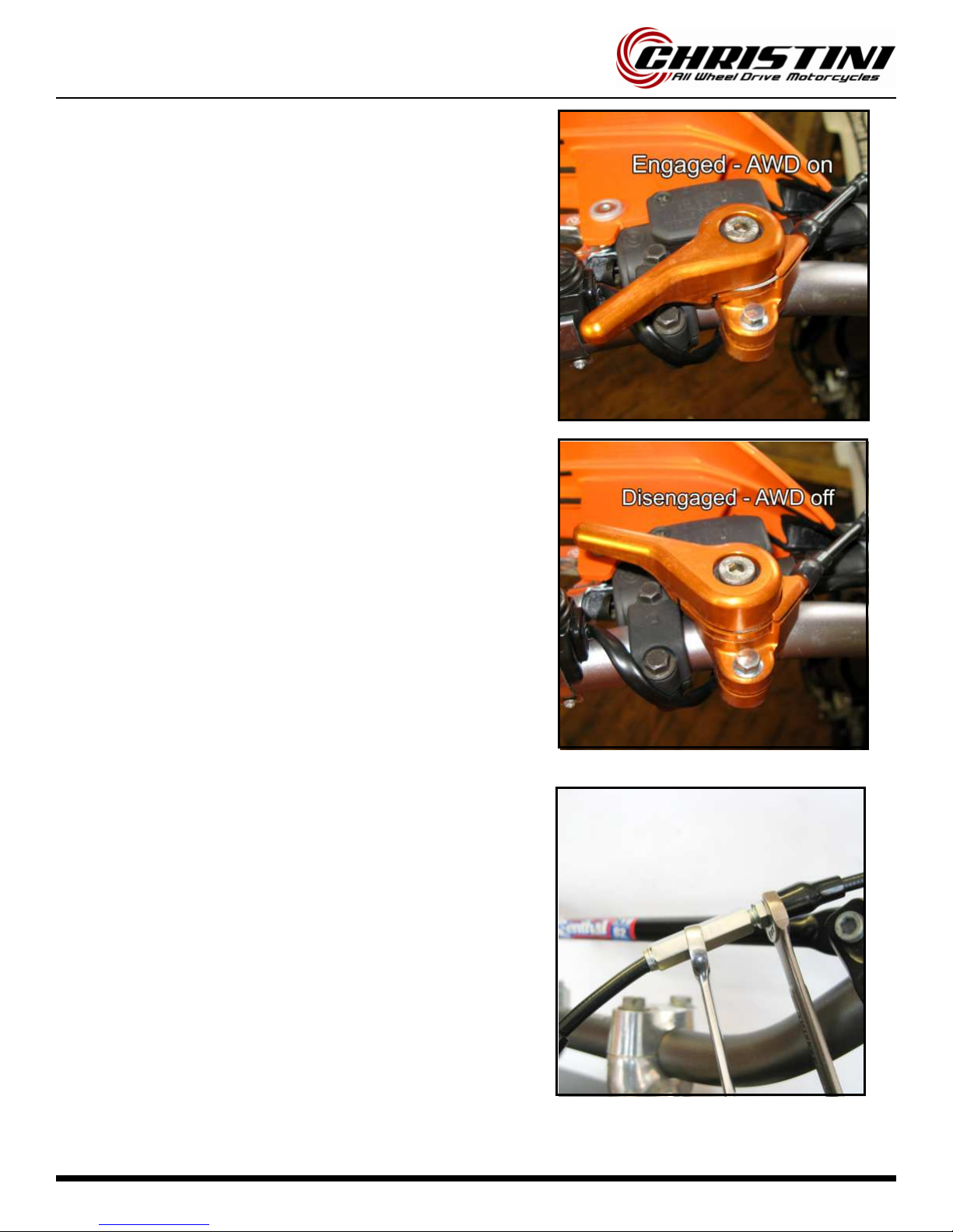
AWD Engagement Adjustment
•
Put motorcycle on a stand so both wheels are off the ground and
make sure the bike is in neutral.
•
Turn engagement switch back towards rider to the on position.
•
Spin rear wheel of motorcycle and make sure that the front wheel
is spinning as well (it may take a few turns before AWD clicks in).
•
Push engagement switch forward to the off position.
•
Spin rear wheel and make sure front wheel is no longer moving.
•
If the front wheel is still moving. Turn barrel adjuster on cable out
until the AWD system disengages and front wheel is no longer
moving.
Page 12
Note:
Note: Note:
Note: Due to AWD hub design, front wheel removal and installation is
aided by removing front caliper first.
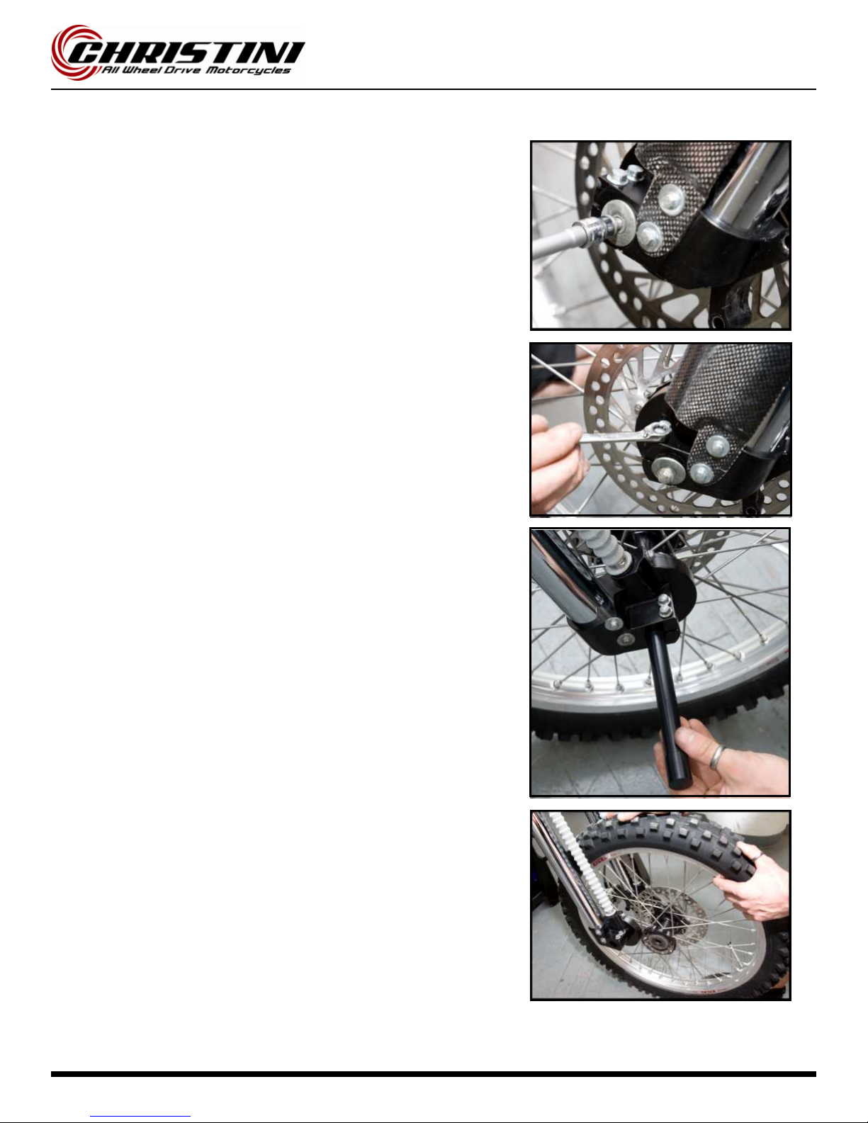
• Remove front brake caliper (note: do not squeeze front brake
lever while caliper is off.
• Remove axle bolt from axle.
• Loosen axle pinch bolts on both sides of dropout.
• Slide axle through wheel and remove.
• Remove front wheel from dropouts.
Note:
Note: Note:
Note: The hub inserts will not fall out like the spacers on a normal hub.
They will also rotate independent of each other; this is ok.
Front Wheel Removal
Page 1
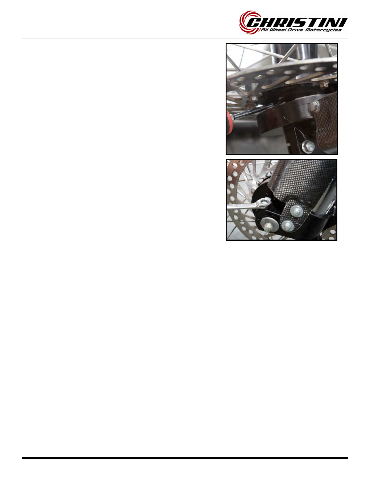
• Lightly grease dropout o-rings and hub seals before installing the
front wheel.
• With brake caliper removed, install front wheel into forks by care-
fully aligning right drive carrier on dropouts with hub inserts. Once
the right carriers are seated, slide axle throug h to other end of
hub.
• Carefully align left carriers and slide axle completely throug h to the
other side. Note, a flat blade screw may be needed to align hub
insert with drive carrier. Note that the hub inserts will only rotate
in one direction in the hub.
• Thread axle bolt back into the end of axle and tighten to 12ft-lb.
Tighten axle pinch bolts to 12 ft-lb. Note:
Note: Note:
Note: If wheel does not spin
freely, axle bolt is too tight!
• Reinstall front brake caliper.
Front Wheel Installation
Page 14
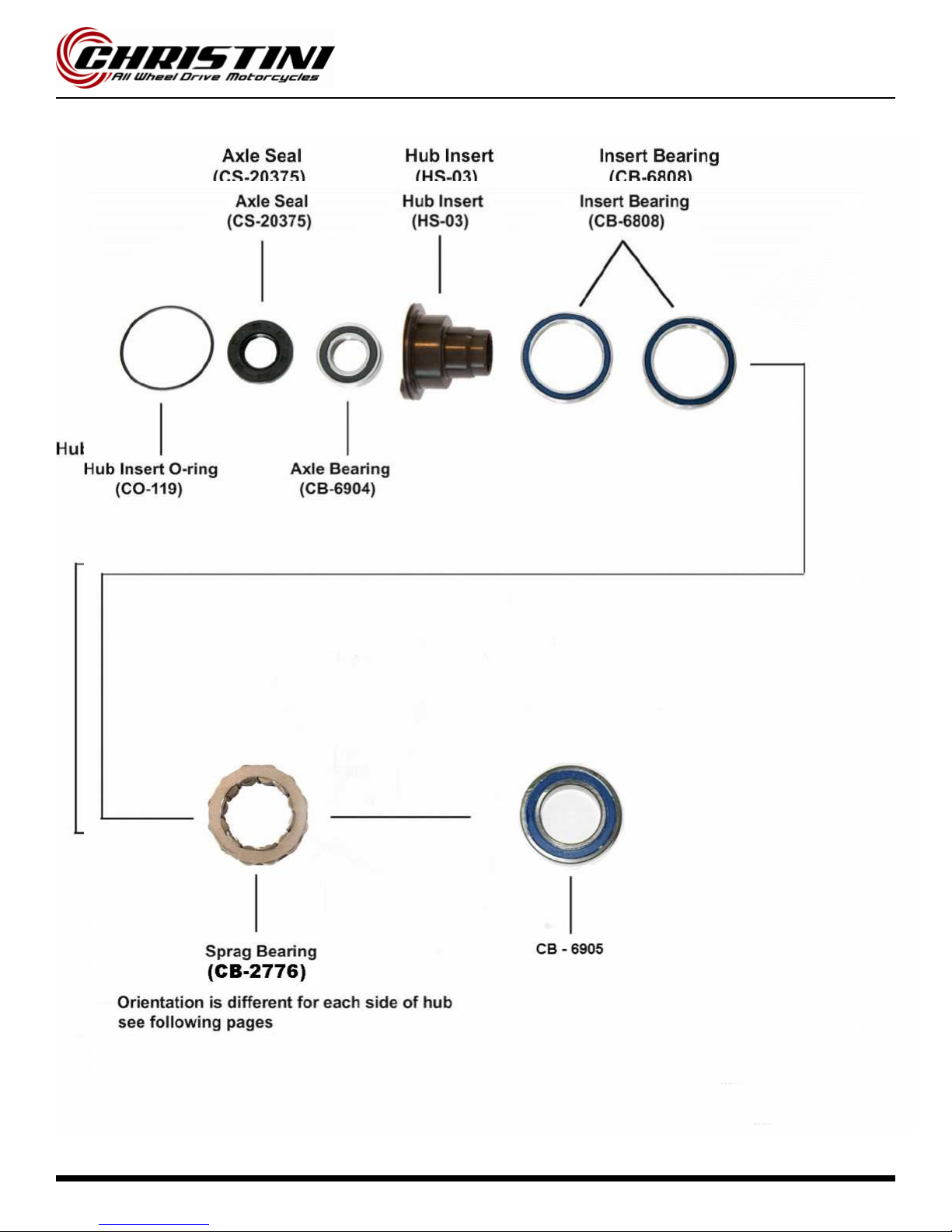
Front Wheel Service

Page 15
Warning:
Warning: Warning:
Warning: efore taking hub apart, make sure that you have a full set
of spare sprag bearings. Sprag bearings are likely to be damaged dur-
ing the disassembly process and new onesmay be required.
•
Using a soft punch, remove the hub inserts from either side of the
hub.
•
Carefully remove all bearings, sprags and spacers from hub with a
punch and hammer. e careful not to tap bearings out crooked as
it may damage hub shell.
Front Wheel Service

Page 16
•
Pry the insert seals out of the inserts using a flat bladed screw-
driver.
•
Remove the hub insert o-rings with a pick.
•
Punch the axle bearings out of the inserts using the access holes
in the back of the inserts.
Front Wheel Service

Page 17
Front Wheel Service
•
Using a bearing punch, install new axle bearings into the hub in-
serts.
•
Press the axle seals into the hub inserts.
•
Install the hub insert o-rings.

Page 18
•
Press C -6905 bearing into the Hub Inner Race
•
e sure that the bearing is seated completely
•
Insert sprag bearing into hub shell. (correct direction will be deter-
mined in next steps.). Lightly grease inside of sprag bearing with
Shell grease.
Front Wheel Service
Warning:
Warning: Warning:
Warning: Sprag bearings must be installed in the correct orientation in the hub for the AWD system to work properly.
If the sprag bearings are not installed correctly, the AWD system can be damaged.

Page 19
•
Test fit hub insert into hub, twisting as it is inserted.
•
Spin the hub insert and check to make sure it is freewheeling in
Spin the hub insert and check to make sure it is freewheeling in Spin the hub insert and check to make sure it is freewheeling in
Spin the hub insert and check to make sure it is freewheeling in
the correct direction.
the correct direction. the correct direction.
the correct direction. If it is not, remove the hub insert and flip the
sprag bearing around. Recheck to verify that hub insert free-
wheels in the correct direction before moving on to next step.
Front Wheel Service
Table of contents
Other Christini Motorcycle manuals


