Beta RR 125 LC User manual

ENGINE SPECIFICATIONS
EAS20290
ENGINE SPECIFICATIONS
Engine
Engine type Liquid cooled 4-stroke, SOHC
Displacement 124.7 cm³
Cylinder arrangement Forward-inclined single cylinder
Bore ×stroke 52.0 ×58.6 mm (2.05 ×2.31 in)
Compression ratio 11.20 :1
Standard compression pressure (at sea level) 550 kPa/600 r/min (5.5 kgf/cm²/600 r/min, 78.2
psi/600 r/min)
Minimum–maximum 480–620 kPa (4.8–6.2 kgf/cm², 68.3–88.2 psi)
Starting system Electric starter
Fuel
Recommended fuel Premium unleaded gasoline only
Fuel tank capacity 8.5 L (2.25 US gal, 1.87 Imp.gal)
Fuel reserve amount 1.6 L (0.42 US gal, 0.35 Imp.gal)
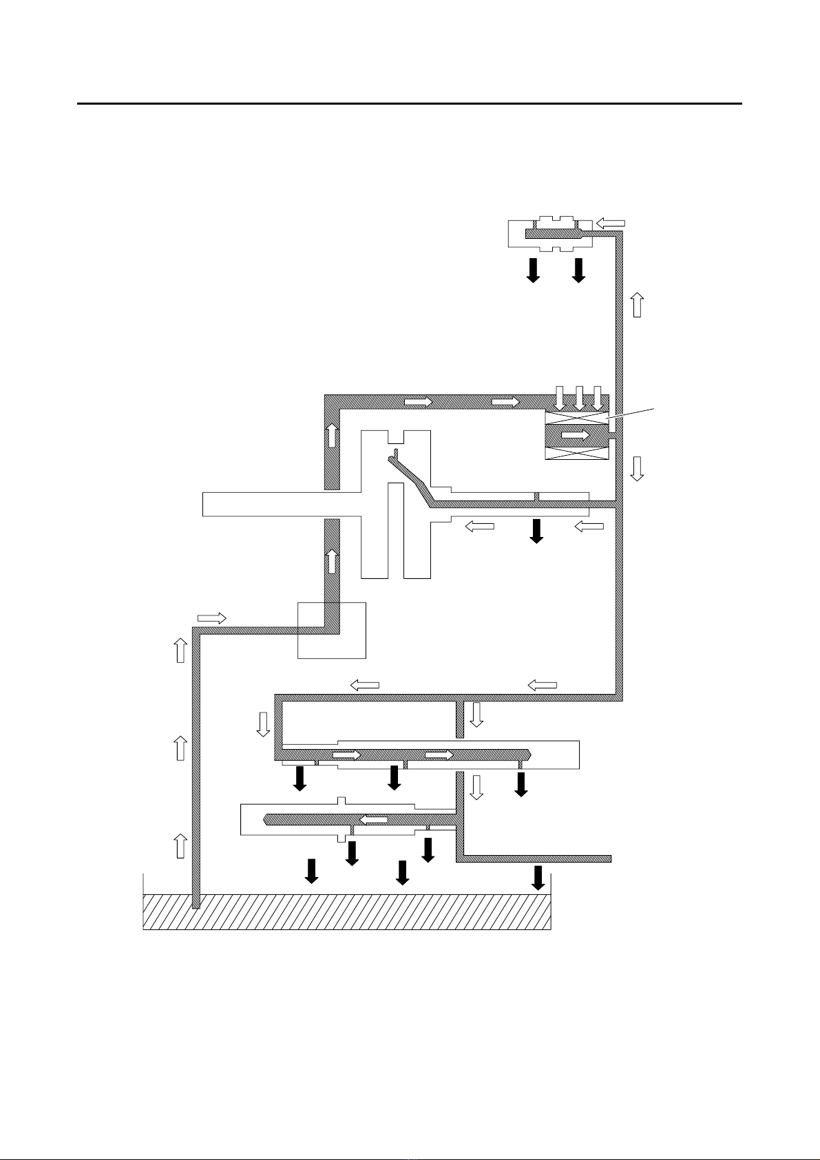
Engine oil
Lubrication system Wet sump
Type SAE 10W-30, SAE 10W-40, SAE 15W-40, SAE
20W-40 or SAE 20W-50
Recommended engine oil grade API service SG type or higher, JASO standard
MA
Engine oil quantity
Total amount 1.15 L (1.22 US qt, 1.01 Imp.qt)
Without oil filter element replacement 0.95 L (1.00 US qt, 0.84 Imp.qt)
With oil filter element replacement 1.00 L (1.06 US qt, 0.88 Imp.qt)
Oil filter
Oil filter type Paper
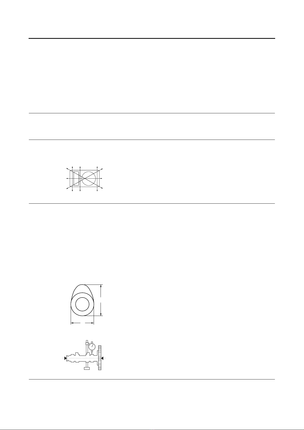
Oil pump
Oil pump type Trochoid
Inner-rotor-to-outer-rotor-tip clearance Less than 0.150 mm (0.0059 in)
Limit 0.23 mm (0.0091 in)
Outer-rotor-to-oil-pump-housing clearance 0.130–0.180 mm (0.0051–0.0071 in)
Limit 0.25 mm (0.0098 in)
Oil-pump-housing-to-inner-and-outer-rotor
clearance 0.06–0.11 mm (0.0024–0.0043 in)
Limit 0.18 mm (0.0071 in)
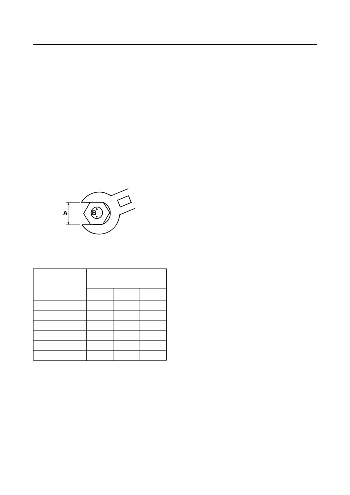
Relief valve operating pressure 39.2–78.4 kPa (0.39–0.78kgf/cm², 5.7–11.4 psi)
Pressure check location Check bolt on cylinder head body

ENGINE SPECIFICATIONS
Valve opening temperature 80.5–83.5 °C (176.90–182.30 °F)
Valve full open temperature 95.0 °C (203.00 °F)
Valve lift (full open) 3.0 mm (0.12 in)
Radiator core
Width 128.0 mm (5.04 in)
Height 258.0 mm (10.16 in)
Depth 24.0 mm (0.94 in)
Water pump
Water pump type Single suction centrifugal pump
Reduction ratio 19/38 (0.500)
Spark plug (s)
Manufacturer/model NGK/CR8E
Spark plug gap 0.7–0.8 mm (0.028–0.031 in)
Cylinder head
Volume 9.90–10.50 cm³(0.60–0.64 cu.in)
Warpage limit 0.03 mm (0.0012 in)
Camshaft
Drive system Chain drive (left)
Camshaft lobe dimensions
Intake A 30.225–30.325 mm (1.1900–1.1939 in)
Limit 30.125 mm (1.1860 in)
Intake B 25.127–25.227 mm (0.9893–0.9932 in)
Limit 25.027 mm (0.9853 in)
Exhaust A 30.232–30.332 mm (1.1902–1.1942 in)
Limit 30.132 mm (1.1863 in)
Exhaust B 25.065–25.165 mm (0.9868–0.9907 in)
Limit 24.965 mm (0.9829 in)
Camshaft runout limit 0.030 mm (0.0012 in)
Timing chain
Model/number of links DID SCR-0404SV/96
A
B

ENGINE SPECIFICATIONS
2-4
Tensioning system Automatic
Rocker arm/rocker arm shaft
Rocker arm inside diameter 9.985–10.000 mm (0.3931–0.3937 in)
Limit 10.015 mm (0.3943 in)
Rocker arm shaft outside diameter 9.966–9.976 mm (0.3924–0.3928 in)
Limit 9.941 mm (0.3914 in)
Rocker-arm-to-rocker-arm-shaft clearance 0.009–0.034 mm (0.0004–0.0013 in)
Limit 0.074 mm (0.0029 in)
Valve, valve seat, valve guide
Valve clearance (cold)
Intake 0.10–0.14 mm (0.0039–0.0055 in)
Exhaust 0.20–0.24 mm (0.0079–0.0094 in)
Valve dimensions
Valve head diameter A (intake) 19.40–19.60 mm (0.7638–0.7717 in)
Valve head diameter A (exhaust) 16.90–17.10 mm (0.6654–0.6732 in)
Valve face width B (intake) 1.538–2.138 mm (0.0606–0.0842 in)
Valve face width B (exhaust) 1.538–2.138 mm (0.0606–0.0842 in)
Valve seat width C (intake) 0.90–1.10 mm (0.0354–0.0433 in)
Limit 1.6 mm (0.06 in)
Valve seat width C (exhaust) 0.90–1.10 mm (0.0354–0.0433 in)
Limit 1.6 mm (0.06 in)
Valve margin thickness D (intake) 0.50–0.90 mm (0.0197–0.0354 in)
Valve margin thickness D (exhaust) 0.50–0.90 mm (0.0197–0.0354 in)
Valve stem diameter (intake) 4.475–4.490 mm (0.1762–0.1768 in)
Limit 4.445 mm (0.1750 in)
Valve stem diameter (exhaust) 4.460–4.475 mm (0.1756–0.1762 in)
Limit 4.430 mm (0.1744 in)
Valve guide inside diameter (intake) 4.500–4.512 mm (0.1772–0.1776 in)
Limit 4.550 mm (0.1791 in)
Valve guide inside diameter (exhaust) 4.500–4.512 mm (0.1772–0.1776 in)
Limit 4.550 mm (0.1791 in)
Valve-stem-to-valve-guide clearance (intake) 0.010–0.037 mm (0.0004–0.0015 in)
Limit 0.080 mm (0.0032 in)
A
B
C
D

ENGINE SPECIFICATIONS
Valve-stem-to-valve-guide clearance (exhaust) 0.025–0.052 mm (0.0010–0.0020 in)
Limit 0.100 mm (0.0039 in)
Valve stem runout 0.010 mm (0.0004 in)
Cylinder head valve seat width (intake) 0.90–1.10 mm (0.0354–0.0433 in)
Limit 1.6 mm (0.06 in)
Cylinder head valve seat width (exhaust) 0.90–1.10 mm (0.0354–0.0433 in)
Limit 1.6 mm (0.06 in)
Valve spring
Free length (intake) 41.71 mm (1.64 in)
Limit 39.62 mm (1.56 in)
Free length (exhaust) 41.71 mm (1.64 in)
Limit 39.62 mm (1.56 in)
Installed length (intake) 35.30 mm (1.39 in)
Installed length (exhaust) 35.30 mm (1.39 in)
Spring rate K1 (intake) 23.54 N/mm (2.40 kgf/mm, 134.41 lb/in)
Spring rate K2 (intake) 36.58 N/mm (3.73 kgf/mm, 208.87 lb/in)
Spring rate K1 (exhaust) 23.54 N/mm (2.40 kgf/mm, 134.41 lb/in)
Spring rate K2 (exhaust) 36.58 N/mm (3.73 kgf/mm, 208.87 lb/in)
Installed compression spring force (intake) 140.00–162.00 N (14.28–16.52 kgf, 31.47–
36.42 lbf)
Installed compression spring force (exhaust) 140.00–162.00 N (14.28–16.52 kgf, 31.47–
36.42 lbf)
Spring tilt (intake) 2.5°/1.8 mm
Spring tilt (exhaust) 2.5°/1.8 mm
Winding direction (intake) Clockwise
Winding direction (exhaust) Clockwise
Cylinder
Bore 52.000–52.010 mm (2.0472–2.0476 in)
Wear limit 52.110 mm (2.0516 in)
Taper limit 0.050 mm (0.0020 in)
Out of round limit 0.005 mm (0.0002 in)
Piston
Piston-to-cylinder clearance 0.015–0.048 mm (0.0006–0.0019 in)
Limit 0.15 mm (0.0059 in)
Diameter D 51.962–51.985 mm (2.0457–2.0466 in)

ENGINE SPECIFICATIONS
Height H 5.0 mm (0.20 in)
Offset 0.50 mm (0.0197 in)
Offset direction Intake side
Piston pin bore inside diameter 14.002–14.013 mm (0.5513–0.5517 in)
Limit 14.043 mm (0.5529 in)
Piston pin outside diameter 13.995–14.000 mm (0.5510–0.5512 in)
Limit 13.975 mm (0.5502 in)
Piston-pin-to-piston-pin-bore clearance 0.002–0.018 mm (0.0001–0.0007 in)
Limit 0.068 mm (0.0027 in)
Piston ring
Top ring
Ring type Barrel
Dimensions (B ×T) 0.80 ×1.90 mm (0.03 ×0.07 in)
End gap (installed) 0.10–0.25 mm (0.0039–0.0098 in)
Limit 0.50 mm (0.0197 in)
Ring side clearance 0.030–0.065 mm (0.0012–0.0026 in)
Limit 0.100 mm (0.0039 in)
2nd ring
Ring type Taper
Dimensions (B ×T) 0.80 ×2.10 mm (0.03 ×0.08 in)
End gap (installed) 0.10–0.25 mm (0.0039–0.0098 in)
Limit 0.60 mm (0.0236 in)
Ring side clearance 0.020–0.055 mm (0.0008–0.0022 in)
Limit 0.100 mm (0.0039 in)
Oil ring
Dimensions (B ×T) 1.50 ×1.95 mm (0.06 ×0.08 in)
End gap (installed) 0.20–0.70 mm (0.0079–0.0276 in)
Ring side clearance 0.040–0.160 mm (0.0016–0.0063 in)
Crankshaft
Width A 47.95–48.00 mm (1.888–1.890 in)
H
D
T
B
B
T
B
T

ENGINE SPECIFICATIONS
Runout limit C 0.030 mm (0.0012 in)
Big end side clearance D 0.110–0.410 mm (0.0043–0.0161 in)
Big end radial clearance E 0.004–0.014 mm (0.0002–0.0006 in)
Balancer
Balancer drive method Gear
Clutch
Clutch type Wet, multiple-disc
Clutch release method Inner push, cam push
Clutch lever free play 10.0–15.0 mm (0.39–0.59 in)
Friction plate 1 thickness 2.90–3.10 mm (0.114–0.122 in)
Wear limit 2.80 mm (0.1102 in)
Plate quantity 1 pc
Friction plate 3 thickness 2.90–3.10 mm (0.114–0.122 in)
Wear limit 2.80 mm (0.1102 in)
Plate quantity 3 pcs
Friction plate 2 thickness 2.90–3.10 mm (0.114–0.122 in)
Wear limit 2.80 mm (0.1102 in)
Plate quantity 1 pc
Clutch plate thickness 1.45–1.75 mm (0.057–0.069 in)
Plate quantity 4 pcs
Warpage limit 0.20 mm (0.0079 in)
Clutch spring free length 38.71 mm (1.52 in)
Minimum length 36.77 mm (1.45 in)
Spring quantity 4 pcs
Long clutch push rod bending limit 0.500 mm (0.0197 in)
Transmission
Transmission type
Primary reduction system
Primary reduction ratio
Secondary reduction system
Secondary reduction ratio
Operation
Constant mesh 6-speed
Helical gear
73/24 (3.042)
Gear ratio
1st 34/12 (2.833)
2nd 30/16 (1.875)
3rd 30/22 (1.364)
4th 24/21 (1.143)
5th 22/23 (0.957)
6th 21/25 (0.840)
Main axle runout limit 0.08 mm (0.0032 in)
D
A
E
CC

TIGHTENING TORQUES
EAS20320
TIGHTENING TORQUES
EAS20330
GENERAL TIGHTENING TORQUE
SPECIFICATIONS
This chart specifies tightening torques for stan-
dard fasteners with a standard ISO thread pitch.
Tightening torque specifications for special com-
ponents or assemblies are provided for each
chapter of this manual. To avoid warpage, tight-
en multi-fastener assemblies in a crisscross pat-
tern and progressive stages until the specified
tightening torque is reached. Unless otherwise
specified, tightening torque specifications re-
quireclean, drythreads. Components shouldbe
at room temperature.
A. Distance between flats
B. Outside thread diameter
A (nut) B (bolt) General tightening
torques
Nm m·kgf ft·lbf
10 mm 6 mm 6 0.6 4.3
12 mm 8 mm 15 1.5 11
14 mm 10 mm 30 3.0 22
17 mm 12 mm 55 5.5 40
19 mm 14 mm 85 8.5 61
22 mm 16 mm 130 13.0 94

TIGHTENING TORQUES
Generator cover tightening sequence:
Clutch cover tightening sequence:
Crankcase tightening sequence:
1,6 7
8
9
5
4
3,11 2,10
8
1,7
3,13 2,12
6
9
5
11
10
4
A
1,7
11
12
3,14
4
5
6
8
9
10
16
15
B
2,13
A. Left crankcase
B. Right crankcase

LUBRICATION SYSTEM CHART AND DIAGRAMS
EAS20390
LUBRICATION SYSTEM CHART AND DIAGRAMS
EAS20400
ENGINE OIL LUBRICATION CHART
1
6
5
2
4
3

LUBRICATION SYSTEM CHART AND DIAGRAMS
EAS20410
LUBRICATION DIAGRAMS
A
1
4
5
6
7
2
3

LUBRICATION SYSTEM CHART AND DIAGRAMS
1
3
2
4

ENGINE
EAS20472
ENGINE
EAS20520
ADJUSTING THE VALVE CLEARANCE
The following procedure applies to all of the
valves.
T
IP
•Valve clearance adjustment should be made
on a cold engine, at room temperature.
•Whenthevalveclearanceistobemeasuredor
adjusted,thepiston mustbeat topdeadcenter
(TDC) on the compression stroke.
1. Remove fuel tank
2. Disconnect:
•Spark plug cap
3. Remove:
4. Spark plug
5. Cylinder head cover
6. Cylinder head cover gasket
4. Remove:
•Timing mark accessing screw “1”
•Crankshaft end accessing screw “2”
5. Measure:
•Valve clearance
Out of specification →Adjust.
▼▼▼▼▼▼▼▼▼ ▼ ▼▼▼▼▼▼▼▼▼ ▼ ▼▼▼▼ ▼ ▼▼▼▼ ▼▼▼
a. Turn the crankshaft counterclockwise.
b. AligntheTDC mark“a”onthegeneratorrotor
with the stationary pointer “b”on the genera-
tor cover.
c. Check that the cam lobes are positioned as
shown in the illustration.
d. Measurethevalveclearancewithathickness
gauge “1”.
Out of specification →Adjust.
▲▲▲▲▲▲▲▲▲ ▲ ▲▲▲▲ ▲ ▲▲▲▲ ▲ ▲▲▲▲ ▲ ▲▲▲▲ ▲▲▲
6. Adjust:
•Valve clearance
▼▼▼▼▼▼▼▼▼ ▼ ▼▼▼▼ ▼ ▼▼▼▼ ▼ ▼▼▼▼ ▼ ▼▼▼▼ ▼▼▼
a. Loosen the locknut “1”.
b. Inserta thickness gauge“2”betweenthe end
of the adjusting screw and the valve tip.
Valve clearance (cold)
Intake
0.10–0.14 mm (0.0039–0.0055 in)
Exhaust
0.20–0.24 mm (0.0079–0.0094 in)
2
1
b
a
1

ENGINE
T
IP
The ignition timing is not adjustable.
▲▲▲▲▲▲▲▲▲ ▲ ▲▲▲▲▲▲▲▲▲ ▲ ▲▲▲▲ ▲ ▲▲▲▲ ▲▲▲
4. Remove:
•Digital tachometer
•Timing light
5. Install:
•Timing mark accessing screw
(along with the O-ring )
EAS20710
MEASURING THE COMPRESSION
PRESSURE
T
IP
Insufficient compression pressure will result in a
loss of performance.
1. Measure:
2. Valve clearance
Out of specification →Adjust.
2. Start the engine, warm it up for several min-
utes, and then turn it off.
3. Disconnect:
•Spark plug cap
4. Remove:
•Spark plug
NOTICE
ECA13330
Before removing the spark plug, blow away
any dirt accumulated in the spark plug well
with compressed air to prevent itfrom falling
into the cylinder.
5. Install:
•Extension “1”
•Compression gauge “2”
6. Measure:
•Compression pressure
Out of specification →Refer to steps (c) and
(d).
▼▼▼▼▼▼▼▼▼ ▼ ▼▼▼▼ ▼ ▼▼▼▼ ▼ ▼▼▼▼ ▼ ▼▼▼▼ ▼▼▼
a. Set the main switch to “ON”.
b. With the throttle wide open, crank the engine
until the reading on the compression gauge
stabilizes.
c. If the compression pressure is above the
maximum specification, check the cylinder
head, valve surfaces and piston crown for
carbon deposits.
Carbon deposits →Eliminate.
d. If the compression pressure is below the min-
imum specification, pour a teaspoonful of en-
gine oil into the spark plug bore and measure
again.
Refer to the following table.
▲▲▲▲▲▲▲▲▲ ▲ ▲▲▲▲ ▲ ▲▲▲▲ ▲ ▲▲▲▲ ▲ ▲▲▲▲ ▲▲▲
7. Remove:
•Extension
•Compression gauge
New
Standard compression pressure
(at sea level)
550 kPa/600 r/min (5.5
kgf/cm²/600 r/min, 78.2 psi/600
r/min)
Minimum–maximum
480–620 kPa (4.8–6.2 kgf/cm²,
68.3–88.2 psi)
Compression pressure (with oil applied into
the cylinder)
Reading Diagnosis
Higher than without
oil Piston ring(s) wear or
damage →Repair.
Same as without oil
Piston, valves, cylin-
der head gasket or
piston ring(s) possi-
bly defective →Re-
pair.
1
2

ENGINE
8. Install:
•Spark plug
9. Connect:
•Spark plug cap
EAS28920
CHECKING THE ENGINE OIL LEVEL
1. Stand the vehicle on a level surface.
T
IP
•Place the vehicle on a suitable stand.
•Make sure the vehicle is upright.
2. Start the engine, warm it up for several min-
utes, and then turn it off.
3. Check:
•Engine oil level
The engine oil level should be between the
minimum level mark “a”and maximum level
mark “b”.
Below the minimum level mark →Add the
recommended engine oil to the proper level.
T
IP
•Before checking the engine oil level, wait afew
minutes until the oil has settled.
•Do not screw the engine oil filler cap (dipstick)
“1”in when checking the oil level.
NOTICE
ECA22B1020
•Engineoil alsolubricatestheclutchandthe
wrong oil types or additives could cause
clutch slippage. Therefore, do not add any
chemicaladditivesor use engine oils witha
grade of “CD”“c”or higher and do not use
oils labeled “ENERGY CONSERVING II”
“d”.
•Do not allow foreign materials to enter the
crankcase.
4. Start the engine, warm it up for several min-
utes, and then turn it off.
5. Check the engine oil level again.
T
IP
Before checking the engine oil level, wait a few
minutes until the oil has settled.
EAS20810
CHANGING THE ENGINE OIL
1. Start the engine, warm it up for several min-
utes, and then turn it off.
2. Place a container under the engine oil drain
plug.
3. Remove:
•Engine oil filler cap (dipstick) “1”
•Engine oil drain plug “2”
•O-ring “3”
•Spring “4”
•Engine oil strainer “5”
T
R
.
.
Spark plug
13 Nm (1.3 m·kgf, 9.4 ft·lbf)
Type
SAE 10W-30, SAE 10W-40, SAE
15W-40, SAE 20W-40 or SAE
20W-50
Recommended engine oil grade
API service SG type or higher,
JASO standard MA
1
1
b
a
-20 -10 0 10 20 30 40 50 ˚C
SAE 10W-30
SAE 15W-40
SAE 20W-40
SAE 20W-50
SAE 10W-40
SAE 10W-50

ENGINE
4. Check:
•Electrode “1”
Damage/wear →Replace the spark plug.
•Insulator “2”
Abnormal color →Replace the spark plug.
Normal color is medium-to-light tan.
5. Clean:
•Spark plug
(with a spark plug cleaner or wire brush)
6. Measure:
•Spark plug gap “a”
(with a wire thickness gauge)
Out of specification →Regap.
7. Install:
•Spark plug
T
IP
Before installing the spark plug, clean the spark
plug and gasket surface.
8. Connect:
•Spark plug cap
EAS20700
CHECKING THE IGNITION TIMING
T
IP
Prior to checking the ignition timing, check the
wiring connections of the entire ignition system.
Make sure all connections are tight and free of
corrosion.
1. Remove:
•Timing mark accessing screw “1”
2. Connect:
•Timing light “1”
•Digital tachometer
3. Check:
•Ignition timing
▼▼▼▼▼▼▼▼▼ ▼ ▼▼▼▼ ▼ ▼▼▼▼ ▼ ▼▼▼▼ ▼ ▼▼▼▼ ▼▼▼
a. Start the engine, warm it up for several min-
utes, and then let it run at the specified en-
gine idling speed.
b. Check that the stationary pointer “a”on the
generator cover is within the firing range “b”
on the generator rotor.
Incorrect firing range →Check the ignition
system.
Spark plug gap
0.7–0.8 mm (0.028–0.031 in)
T
R
.
.
Spark plug
13 Nm (1.3 m·kgf, 9.4 ft·lbf)
Engine idling speed
1400–1600 r/min
1
1
a
bb

ENGINE
4. Drain:
•Engine oil
(completely from the crankcase)
5. If the oil filter element is also to be replaced,
perform the following procedure.
▼▼▼▼▼▼▼▼▼ ▼ ▼▼▼▼▼▼▼▼▼ ▼ ▼▼▼▼ ▼ ▼▼▼▼ ▼▼▼
a. Remove the oil filterelement cover “1”andoil
filter element “2”.
b. Install a new O-ring “3”.
c. Install the new oil filter element and the oil fil-
ter element cover.
▲▲▲▲▲▲▲▲▲ ▲ ▲▲▲▲▲▲▲▲▲ ▲ ▲▲▲▲ ▲ ▲▲▲▲ ▲▲▲
6. Check:
•Engine oil strainer
Dirt →Clean.
7. Install:
•Engine oil strainer
•Spring
•O-ring
•Engine oil drain plug
8. Fill:
•Crankcase
(with the specified amount of the recom-
mended engine oil)
9. Install:
•Engine oil filler cap (dipstick)
10.Start the engine, warm it up for several min-
utes, and then turn it off.
11.Check:
•Engine
(for engine oil leaks)
12.Check:
•Engine oil level
13.Check:
•Engine oil pressure
▼▼▼▼▼▼▼▼▼ ▼ ▼▼▼▼ ▼ ▼▼▼▼ ▼ ▼▼▼▼ ▼ ▼▼▼▼ ▼▼▼
a. Slightly loosen the oil check bolt “1”.
b. Starttheengineandkeepitidlinguntilengine
oil starts to seep from the oil check bolt. If no
engine oil comes out after one minute, turn
the engine off so that it will not seize.
c. Check the engine oil passages, the oil filter
element and the oil pump for damage or leak-
age.
T
R
.
.
Oil filter element cover bolt
10 Nm (1.0 m·kgf, 7.2 ft·lbf)
1
2
5
4
3
2
1
2
3New
T
R
.
.
Engine oil drain plug
32 Nm (3.2 m·kgf, 23 ft·lbf)
Engine oil quantity
Total amount
1.15 L (1.22 US qt, 1.01 Imp.qt)
Without oil filter element replace-
ment
0.95 L (1.00 US qt, 0.84 Imp.qt)
With oil filter element replace-
ment
1.00 L (1.06 US qt, 0.88 Imp.qt)
New
1

ENGINE
d. Start the engine after solving the problem(s)
and check the engine oil pressure again.
e. Tighten the oil check bolt to specification.
T
R
.
.
Oil check bolt
7 Nm (0.7 m·kgf, 5.1 ft·lbf)

CYLINDER HEAD
EAS24100
CYLINDER HEAD
Removing the cylinder head
Order Job/Parts to remove Q’ty Remarks
Seat/Fuel tank cover assembly/Air filter case
Coolant
Muffler/Exhaust pipe
Clutch cable
Fuel tank
Throttle body/Intake manifold
Radiator
Thermostat/Coolant temperature sensor
Water pump
1 Spark plug cap 1
2 Spark plug 1
3 Crankshaft end accessing screw 1
4 Timing mark accessing screw 1
New
New
New
New New
New
E
E
(4)
12 11
14
15
16
15
13
6
7
1
2
(4)
(4)
10 9
8
5
4
3
5
E
LS
M
LS
10 Nm (1.0 m•kgf, 7.2 ft•Ibf)
T
.R.
10 Nm (1.0 m•kgf, 7.2 ft•Ibf)
T
.R.
10 Nm (1.0 m•kgf, 7.2 ft•Ibf)
T
.R.
10 Nm (1.0 m•kgf, 7.2 ft•Ibf)
T
.R.
7 Nm (0.7 m•kgf, 5.1 ft•Ibf)
T
.R.
13 Nm (1.3 m•kgf, 9.4 ft•Ibf)
T
.R.
22 Nm (2.2 m•kgf, 16 ft•Ibf)
T
.R.
30 Nm (3.0 m•kgf, 22 ft•Ibf)
T
.R.
*
67 Nm (6.7 m•kgf, 48 ft•Ibf)
T
.R.

CYLINDER HEAD
5 Engine front upper mounting bolt/nut 1/1
6 Cylinder head cover 1
7 Cylinder head cover gasket 1
8 Clutch cable holder 1
9 Timing chain tensioner 1
10 Timing chain tensioner gasket 1
11 Camshaft sprocket 1
12 Decompression cam 1
13 Cylinder head 1
14 Cylinder head gasket 1
15 Dowel pin 2
16 Timing chain guide (exhaust side) 1
Removing the cylinder head
Order Job/Parts to remove Q’ty Remarks
New
New
New
New New
New
E
E
(4)
12 11
14
15
16
15
13
6
7
1
2
(4)
(4)
10 9
8
5
4
3
5
E
LS
M
LS
10 Nm (1.0 m•kgf, 7.2 ft•Ibf)
T
.R.
10 Nm (1.0 m•kgf, 7.2 ft•Ibf)
T
.R.
10 Nm (1.0 m•kgf, 7.2 ft•Ibf)
T
.R.
10 Nm (1.0 m•kgf, 7.2 ft•Ibf)
T
.R.
7 Nm (0.7 m•kgf, 5.1 ft•Ibf)
T
.R.
13 Nm (1.3 m•kgf, 9.4 ft•Ibf)
T
.R.
22 Nm (2.2 m•kgf, 16 ft•Ibf)
T
.R.
30 Nm (3.0 m•kgf, 22 ft•Ibf)
T
.R.
*
67 Nm (6.7 m•kgf, 48 ft•Ibf)
T
.R.

CYLINDER HEAD
EAS24130
REMOVING THE CYLINDER HEAD
1. Align:
•“I”mark “a”on the generator rotor
(with the stationary pointer “b”on the genera-
tor cover)
▼▼▼▼▼▼▼▼▼ ▼ ▼▼▼▼▼▼▼▼▼ ▼ ▼▼▼▼ ▼ ▼▼▼▼ ▼▼▼
a. Turn the crankshaft counterclockwise.
b. When the piston is at TDC on the compres-
sion stroke, align the “I”mark “c”on the cam-
shaft sprocket with the stationary pointer “d”
on the cylinder head.
▲▲▲▲▲▲▲▲▲ ▲ ▲▲▲▲▲▲▲▲▲ ▲ ▲▲▲▲ ▲ ▲▲▲▲ ▲▲▲
2. Loosen:
•Camshaft sprocket bolt “1”
T
IP
While holding the generator rotor nut with a
wrench “2”, loosen the camshaft sprocket bolt.
3. Remove:
•Camshaft sprocket
T
IP
To prevent the timing chain from falling into the
crankcase, fasten it with a wire “1”.
4. Remove:
•Cylinder head
T
IP
•Loosen the bolts in the proper sequence as
shown.
•Loosen each bolt 1/2 of a turn at a time. After
all of the bolts are fully loosened,remove them.
•Remove the cylinder head from the right side
of the vehicle.
EAS24160
CHECKING THE CYLINDER HEAD
1. Eliminate:
•Combustion chamber carbon deposits
(with a rounded scraper)
T
IP
Do not use a sharp instrument to avoid damag-
ing or scratching:
•Spark plug bore threads
•Valve seats
b
a
d
c
1
1
1
2
1
351
2
4
6
Table of contents
Other Beta Motorcycle manuals

Beta
Beta Evo 2T 2011 User manual

Beta
Beta EVO 2T User guide

Beta
Beta 350-498 RR User guide

Beta
Beta MINITRIAL 50 User manual

Beta
Beta RR 50 CC ENDURO User manual

Beta
Beta RR 350 User manual

Beta
Beta RR 4T-400 Instruction manual

Beta
Beta RR 250 2T EUROPA 2019 User manual

Beta
Beta ALP 125 cc User manual

Beta
Beta RE 125 User manual

Beta
Beta Rev 4T User manual

Beta
Beta ALP 200 User manual

Beta
Beta 2008 URBAN 125cc User manual

Beta
Beta EVO 80 User manual

Beta
Beta RR 50 cc ENDURO User manual

Beta
Beta 125 RR-S 2020 User manual

Beta
Beta RR 4T-250 Instruction manual

Beta
Beta REV 3 User manual

Beta
Beta RR 50 CC series User manual

Beta
Beta RR 300 2T User manual