2
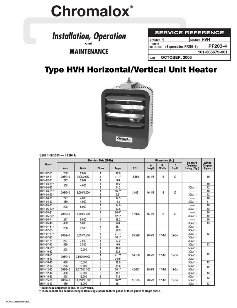
Specifications – Table A
Model Volts Watts Phase Amps BTU
A
Height
B
Width
C
Depth
Std. Contactor
Rating (Qty.)
Wiring
Dia. Figure
HVH-02-81 208 2,667 1 12.8 8,850 16-1/8 13 10 —— 10
HVH-02-21 208/240 2000/2,667 1 11.1* 8,850 16-1/8 13 10 —— 10
HVH-02-71 277 2,667 1 9.6 8,850 16-1/8 13 10 —— 10
HVH-04-81† 208 4,000 1 19.2 13,661 16-1/8 13 10 —— 10
HVH-04-83† 208 4,000 3 11.2 13,661 16-1/8 13 10 30A (1) 12
HVH-04-21† 208/240 3,000/4,000 1 16.7* 13,661 16-1/8 13 10 —— 10
HVH-04-23† 208/240 3,000/4,000 3 9.6* 13,661 16-1/8 13 10 30A (1) 12
HVH-04-71 277 4,000 1 14.5 13,661 16-1/8 13 10 —— 10
HVH-04-43 480 4,000 3 4.8 13,661 16-1/8 13 10 30A (1) 11
HVH-05-81† 208 5,000 1 24.0 17,076 16-1/8 13 10 —— 10
HVH-05-83† 208 5,000 3 13.8 17,076 16-1/8 13 10 30A (1) 12
HVH-05-21† 208/240 3,750/5,000 1 20.8* 17,076 16-1/8 13 10 —— 10
HVH-05-23† 208/240 3,750/5,000 3 12.1* 17,076 16-1/8 13 10 30A (1) 12
HVH-05-71 277 5,000 1 18.2 17,076 16-1/8 13 10 —— 10
HVH-05-43 480 5,000 3 6.0 17,076 16-1/8 13 10 30A (1) 13
HVH-07-81† 208 7,500 1 36.1 25,598 20-5/8 17-1/8 12-3/4 50A (1) 12
HVH-07-83 208 7,500 3 20.9 25,598 20-5/8 17-1/8 12-3/4 30A (1) 12
HVH-07-21† 208/240 5,625/7,500 1 31.1* 25,598 20-5/8 17-1/8 12-3/4 30A (1) 12
HVH-07-23 208/240 5,625/7,500 3 18.1* 25,598 20-5/8 17-1/8 12-3/4 30A (1) 12
HVH-07-71 277 7,500 1 27.2 25,598 20-5/8 17-1/8 12-3/4 30A (1) 12
HVH-07-43 480 7,500 3 9.0 25,598 20-5/8 17-1/8 12-3/4 30A (1) 13
HVH-10-81† 208 10,000 1 48.0 34,130 20-5/8 17-1/8 12-3/4 50A (1) 12
HVH-10-83 208 10,000 3 27.8 34,130 20-5/8 17-1/8 12-3/4 30A (1) 12
HVH-10-21† 208/240 7,500/10,000 1 41.7* 34,130 20-5/8 17-1/8 12-3/4 30A (1) 12
HVH-10-23 208/240 7,500/10,000 3 24.0* 34,130 20-5/8 17-1/8 12-3/4 30A (1) 12
HVH-10-43 480 10,000 3 12.0 34,130 20-5/8 17-1/8 12-3/4 30A (1) 13
HVH-12-83 208 12,500 3 34.8 42,663 20-5/8 17-1/8 12-3/4 50A (1) 12
HVH-12-23 208/240 9,375/12,500 3 30.1* 42,663 20-5/8 17-1/8 12-3/4 50A (1) 12
HVH-12-43 480 12,500 3 15.1 42,663 20-5/8 17-1/8 12-3/4 30A (1) 13
HVH-15-83 208 15,000 3 41.8 51,195 20-5/8 17-1/8 12-3/4 50A (1) 12
HVH-15-23 208/240 11,250/13,000 3 36.2* 51,195 20-5/8 17-1/8 12-3/4 50A (1) 12
HVH-15-43 480 15,000 3 18.1 51,195 20-5/8 17-1/8 12-3/4 30A (1) 13
HVH-20-23 208/240 14,758/19,500 3 47.0 66,534 20-5/8 17-1/8 14-1/16 50A (2) 15
HVH-20-43 480 19,500 3 23.5 66,534 20-5/8 17-1/8 14-1/16 50A (1) 14
HVH-20-63 600 19,500 3 18.8 66,534 20-5/8 17-1/8 14-1/16 50A (1) 14
HVH-25-23 208/240 18,720/24,900 3 60.0 84,959 29-3/16 26-1/16 14-5/8 50A (2) 15
HVH-25-43 480 25,000 3 30.2 85,300 29-3/16 26-1/16 14-5/8 50A (1) 14
HVH-25-63 600 25,000 3 24.1 85,300 29-3/16 26-1/16 14-5/8 50A (1) 14
HVH-30-23 208/240 22,400/29,900 3 72.1 102,019 29-3/16 26-1/16 14-5/8 50A (2) 15
HVH-30-43 480 30,000 3 36.2 102,360 29-3/16 26-1/16 14-5/8 50A (1) 14
HVH-30-63 600 30,000 3 29 102,360 29-3/16 26-1/16 14-5/8 50A (1) 14
HVH-35-23 208/240 25,600/34,000 3 81.9 116,008 29-3/16 26-1/16 14-5/8 50A (3) 15
HVH-35-43 480 34,000 3 41 116,008 29-3/16 26-1/16 14-5/8 50A (1) 14
HVH-35-63 600 34,200 3 33 116,690 29-3/16 26-1/16 14-5/8 50A (1) 14
HVH-40-23 208/240 28,000/37,400 3 90.1 127,609 29-3/16 26-1/16 14-5/8 50A (3) 16
HVH-40-43 480 37,400 3 45.1 127,609 29-3/16 26-1/16 14-5/8 50A (1) 14
HVH-40-63 600 37,500 3 36.2 127,950 29-3/16 26-1/16 14-5/8 50A (1) 14
HVH-45-23 208/240 33,700/44,800 3 107.9 152,858 29-3/16 26-1/16 14-5/8 50A (3) 16
HVH-45-43 480 44,800 3 54 152,858 29-3/16 26-1/16 14-5/8 50A (2) 15
HVH-45-63 600 45,200 3 43.6 154,222 29-3/16 26-1/16 14-5/8 50A (1) 14
HVH-50-23 208/240 38,400/50,000 3 123.1 174,353 29-3/16 26-1/16 14-5/8 50A (3) 16
HVH-50-43 480 50,000 3 61.6 174,353 29-3/16 26-1/16 14-5/8 50A (2) 15
HVH-50-63 600 50,000 3 49.5 175,036 29-3/16 26-1/16 14-5/8 50A (2) 15
* Note: 208V amperage is 86% of 240V value.
† These models can be field changed from single phase to three phase or three phase to single phase.
WARNING (cont’d.)
The ceiling mounting structure and the anchoring provisions must
be of sufficient strength to support the combined weight of the heater
and mounting bracket. (Refer to Table B for weights of heater and
bracket.)
The wall or mounting surface, and the anchoring provisions
must be capable of supporting the combined weight of the heater and
mounting brackets cantilevered from the mounting surface. (Refer to
Table B for weights of heater and brackets and for cantilevered force
expressed in foot-pounds.)
Fan blade rotation must be checked. If airflow is not moving out
through the louvers, interchange any two of the three customer power
leads on three-phase units only.
Table B – Weights of Heater & Bracket
Model
WEIGHT (Lbs.) Heater and Brackets
Ceiling
Weight
Wall
Weight Ft.-Lbs.
HVH-02 to HVH-05 27 25-1/2 48
HVH-15 to HVH-20 55 67-1/4 112
HVH-25, 30, 35 108 105 126.3
HVH-40, 45, 50 118 115 138.4


